EP2860036B1 - Dispositif d'impression, imprimante et procédé de fonctionnement d'un dispositif d'impression - Google Patents
Dispositif d'impression, imprimante et procédé de fonctionnement d'un dispositif d'impression Download PDFInfo
- Publication number
- EP2860036B1 EP2860036B1 EP13004852.3A EP13004852A EP2860036B1 EP 2860036 B1 EP2860036 B1 EP 2860036B1 EP 13004852 A EP13004852 A EP 13004852A EP 2860036 B1 EP2860036 B1 EP 2860036B1
- Authority
- EP
- European Patent Office
- Prior art keywords
- printing
- print heads
- ink
- axis
- Prior art date
- Legal status (The legal status is an assumption and is not a legal conclusion. Google has not performed a legal analysis and makes no representation as to the accuracy of the status listed.)
- Active
Links
Images


Classifications
-
- B—PERFORMING OPERATIONS; TRANSPORTING
- B41—PRINTING; LINING MACHINES; TYPEWRITERS; STAMPS
- B41J—TYPEWRITERS; SELECTIVE PRINTING MECHANISMS, i.e. MECHANISMS PRINTING OTHERWISE THAN FROM A FORME; CORRECTION OF TYPOGRAPHICAL ERRORS
- B41J3/00—Typewriters or selective printing or marking mechanisms characterised by the purpose for which they are constructed
- B41J3/54—Typewriters or selective printing or marking mechanisms characterised by the purpose for which they are constructed with two or more sets of type or printing elements
- B41J3/543—Typewriters or selective printing or marking mechanisms characterised by the purpose for which they are constructed with two or more sets of type or printing elements with multiple inkjet print heads
-
- B—PERFORMING OPERATIONS; TRANSPORTING
- B41—PRINTING; LINING MACHINES; TYPEWRITERS; STAMPS
- B41J—TYPEWRITERS; SELECTIVE PRINTING MECHANISMS, i.e. MECHANISMS PRINTING OTHERWISE THAN FROM A FORME; CORRECTION OF TYPOGRAPHICAL ERRORS
- B41J25/00—Actions or mechanisms not otherwise provided for
- B41J25/001—Mechanisms for bodily moving print heads or carriages parallel to the paper surface
-
- B—PERFORMING OPERATIONS; TRANSPORTING
- B41—PRINTING; LINING MACHINES; TYPEWRITERS; STAMPS
- B41J—TYPEWRITERS; SELECTIVE PRINTING MECHANISMS, i.e. MECHANISMS PRINTING OTHERWISE THAN FROM A FORME; CORRECTION OF TYPOGRAPHICAL ERRORS
- B41J3/00—Typewriters or selective printing or marking mechanisms characterised by the purpose for which they are constructed
- B41J3/407—Typewriters or selective printing or marking mechanisms characterised by the purpose for which they are constructed for marking on special material
- B41J3/4073—Printing on three-dimensional objects not being in sheet or web form, e.g. spherical or cubic objects
-
- B—PERFORMING OPERATIONS; TRANSPORTING
- B41—PRINTING; LINING MACHINES; TYPEWRITERS; STAMPS
- B41J—TYPEWRITERS; SELECTIVE PRINTING MECHANISMS, i.e. MECHANISMS PRINTING OTHERWISE THAN FROM A FORME; CORRECTION OF TYPOGRAPHICAL ERRORS
- B41J3/00—Typewriters or selective printing or marking mechanisms characterised by the purpose for which they are constructed
- B41J3/407—Typewriters or selective printing or marking mechanisms characterised by the purpose for which they are constructed for marking on special material
- B41J3/4073—Printing on three-dimensional objects not being in sheet or web form, e.g. spherical or cubic objects
- B41J3/40733—Printing on cylindrical or rotationally symmetrical objects, e. g. on bottles
-
- B—PERFORMING OPERATIONS; TRANSPORTING
- B41—PRINTING; LINING MACHINES; TYPEWRITERS; STAMPS
- B41J—TYPEWRITERS; SELECTIVE PRINTING MECHANISMS, i.e. MECHANISMS PRINTING OTHERWISE THAN FROM A FORME; CORRECTION OF TYPOGRAPHICAL ERRORS
- B41J2/00—Typewriters or selective printing mechanisms characterised by the printing or marking process for which they are designed
- B41J2/005—Typewriters or selective printing mechanisms characterised by the printing or marking process for which they are designed characterised by bringing liquid or particles selectively into contact with a printing material
- B41J2/01—Ink jet
- B41J2/135—Nozzles
- B41J2/165—Prevention or detection of nozzle clogging, e.g. cleaning, capping or moistening for nozzles
Definitions
- the invention relates to a printing machine with a printing device for printing on a peripheral surface of an object, with at least two printheads, each having at least one row of Farbdosierianan, especially ink nozzles, each of which is designed for an individual predefinable release of color to the object. Furthermore, the invention relates to a method for operating a printing press with a printing device.
- a printing device for printing on the surface of a three-dimensional object comprising an ink jet printing system with a plurality of circumferentially adjacent to each other at a fixed distance arranged individual print heads, which can be moved during the execution of the printing operation along an axis of rotation for the object to be printed to a helical Allowing printing of the article, wherein a pitch between adjacent nozzles of the individual print heads is greater than a resolution of the image to be applied to the printed image and wherein the desired resolution is achieved by the helical printing of the article.
- the EP 2 471 665 A1 discloses a marking and / or scanning head having a plurality of receiving spaces, in which individual marking and / or sensor devices can be arranged for marking and / or scanning an object, wherein the receiving spaces are arranged in at least two subarrays, wherein at least one subarray is movable and / or rotatable relative to at least one other subarray, wherein the marking and / or scanning head further comprises a holding frame, which are arranged at least two sub-arrays on a common mounting frame, which is movable and / or rotatable relative to the holding frame, the sub-arrays are each about an axis of rotation, which passes through the center of the corresponding sub-array rotatable and the receiving spaces of each sub-array are arranged in a plurality of rows and columns to form a two-dimensional array of receiving spaces.
- the US 2011/084995 A1 discloses an ink jet printing method comprising the steps of: performing a print job within a print area using two or more print units, the print units being determined to be active; Determining one of the printing units as the idle printing unit; Moving the idle printing unit from the printing area to a maintenance area; Moving a predetermined idle pressure unit from the maintenance area to the pressure area; Determining the previously named idle printing unit as active; and continuing execution of the print job using two or more print engines that are currently designated as active.
- a printing machine for printing on cylindrical hollow bodies in which an ink jet printing method is used and in which opposite to an ink jet print head, a cleaning arrangement is mounted, which is designed for a cleaning of the ink jet print head.
- the CH 695 555 A5 discloses a printing machine for three-dimensional printing objects, comprising a printing device for applying at least one colorant to a printing object and with a drying device for drying the colorant, the printing device having one or more print heads and wherein the print heads and the drying device are arranged such that the drying of Color medium of a printed image can be done before its completion.
- the object of the invention is to provide a printing machine and a method for operating a printing press with a printing device, with which a particularly efficient printing of a high-resolution object is made possible.
- the print head has a plurality of ink dosing elements arranged along an extension axis, wherein each of the ink dosing elements is designed for individual dispensing of color particles or drops of ink, in particular ink droplets.
- the Farbdosierieri are arranged at a constant pitch along the extension axis, so that each adjacent Farbdosierieri have a constant distance from each other.
- the along the extension axis arranged Farbdosieretti form a print line, wherein a print head can be equipped with one or alternatively with multiple print lines, wherein a plurality of print lines are preferably arranged parallel to each other and with the same distance.
- a relative movement of a first print head relative to a second print head is made possible.
- This relative movement can influence which position the ink metering elements of the first print head occupy along the extension axis relative to the ink metering elements of the second print head.
- the Farbdosierimplantation the first print head are offset with respect to the extension axis by an amount relative to the Farbdosier instituten the second print head, which corresponds to 50 percent of the pitch of the Farbdosier institute.
- an adjustment of the position of the ink metering elements to print tracks can be achieved which have different slopes due to different requirements for the resolution of the print image to be generated and / or due to different diameters of the articles to be printed .
- an adjustment of the pitch for the helical print track must be achieved, depending on the desired resolution for the print image to be generated and depending on the diameter of the article, which is achieved by adjusting the relative position of the print heads by relative movement the extension axis can be guaranteed to each other.
- a change in the resolution of the printed image along the extension axis can also be provided during the execution of a printing operation, which is of interest, for example, if partial regions of the printed image are to be produced with higher resolution than other regions of the printed image.
- the object to be printed relative to the printing device performs a relative movement, which is aligned at least substantially, in particular exactly, transversely to the extension axis of the Farbdosieriata.
- This relative movement of the object relative to the printing device may in particular be a pure translational movement, a pure rotational movement or an overlay of a translational movement and a rotational movement.
- a helical printing of the article is provided, which is optionally by a, in particular synchronous, translational movement of the printing heads along the axis of extension in exclusive rotation of the article or by a superimposed rotational and translational movement of the article relative to the stationary printheads or by a combination of a superimposed rotary and translational movement of the article with a, in particular synchronous, translational movement of the print heads along the extension axis can be performed. It can be provided that the relative position of the print heads along the extension axis to each other depending on the achievable resolution and / or the diameter of the article before the implementation of the printing process is set and maintained during the execution of the printing operation.
- the at least one further print head in particular all other print heads, is connected to an electrically controllable setting device and arranged movably along the extension axis of the ink metering elements on the print head carrier.
- each of the print heads in particular also during the execution of a printing operation for an object, can be adjusted with regard to its positioning along the extension axis of the ink metering elements.
- the image to be printed on the peripheral surface of the object to be printed has, for example, a print area with low expansion and high image resolution along the extension axis and surrounding print areas with greater expansion and lower image resolution along the extension axis, then it can be provided that the print heads are used to generate the print area high resolution relative position to each other, which differs from a relative positioning of the printheads to produce the low-resolution printing areas.
- the print heads are aligned parallel to each other and transverse to the extension axis of the Farbdosieriata immediately adjacent, in particular slidably adjacent to each other, are arranged.
- the juxtaposed Farbdosieriata the adjacent printheads are each parallel aligned with each other and arranged transversely to the extension axis, in particular with respect to a circumferential direction of the object to be printed, at a fixed distance from each other.
- it may also be provided to make a spacing of the print heads transversely to the extension axis adjustable by suitable adjustment means.
- it may be provided to arrange at least one print head rotatably mounted about a pivot axis, wherein the pivot axis is preferably aligned parallel to the extension axis, so that an incident direction for the color particles emitted by the print head, in particular ink drops, can be adjusted to the outer surface of the object. This is of particular interest when articles with very different diameters are to be printed with the same printing device.
- the printheads by means of at least one adjustment between a first functional position in which the Farbdosieriana adjacent printheads are arranged transversely to extension axis overlapping, and a second functional position in which an overlap of Farbdosierierin adjacent printheads transversely to extension axis present, are adjustable.
- a first functional position in which the Farbdosierimplantation adjacent printheads are arranged transversely to extension axis overlapping
- a second functional position in which an overlap of Farbdosierettin adjacent printheads transversely to extension axis present
- At least part of the ink metering elements of the first print head lie on the same parallel lines as at least part of the ink metering elements of the second print head.
- a higher print resolution along the extension axis can be achieved than and the areas without overlap. This is especially true in the event that each surface area of the object to be printed is only passed over once by the printheads.
- At least one print head comprises at least two rows of color metering elements aligned parallel to the extension axis, in particular as ink nozzles.
- the at least two rows of Farbdosierierin along the extension axis each have the same pitch for the Farbdosier sculpture.
- the Farbdosierimplantation adjacent rows relative to the extension axis by a predetermined amount, in particular by a fraction of the respective pitch offset from each other.
- adjacent rows of Farbdosierettin for dispensing different colors, especially cyan, magenta and yellow (yellow) provided are.
- the respective print head can generate the entire associated image section of the print image during a printing process, whereby depending on the printing method used, in particular when using the inkjet printer process, predictable mixing of the colors emitted by the different ink dosing elements occurs.
- the Farbdosieretti along the extension axis are arranged in a predetermined pitch and that the adjustment is designed for positioning of the print head with a positioning accuracy, the smaller, preferably less than 50 percent, preferably less than 25 percent, more preferably less than 10 percent, in particular less than two percent, the pitch of the Farbdosierieri along the extension axis.
- the respective printhead can be arranged in a reproducible manner relative to adjacent printheads, for example, to allow for different resolutions and different printing speeds for the printing of the article during the execution of a printing operation.
- the setting device has a positioning accuracy of less than 5 micrometers and that a pitch of the ink metering elements is in a range of 0.25 millimeters.
- each group of print heads comprises at least one, in particular two, print heads.
- the peripheral surface of an article may optionally be subjected to a single rotation or possibly only a partial rotation high resolution in the circumferential direction and / or printed along the extension axis, for which purpose the two groups of print heads are arranged at least partially overlapping each other.
- the peripheral surface of the object may be provided to print the peripheral surface of the object in the course of several revolutions, with no or only a slight overlap of the groups of printheads being provided for each other and the printheads of the adjacent groups of printing heads being adjusted to one another depending on the desired pitch of the printing track , It is preferred that the respective groups of printheads are each designed to dispense a single color.
- the printhead support is associated with a drying station arranged opposite the print heads, in order to allow drying of the applied ink following the application of paint.
- a curing process is carried out for the color particles or drops of color emitted by the ink dosing elements onto the surface of the object to be printed.
- a contactless energy coupling for example by infrared light or ultraviolet light, is preferably provided on the object.
- Such a drying or curing process is particularly advantageous when the article is an at least substantially rotationally symmetric article which is rotated during the printing operation about an axis of rotation which is aligned at least substantially parallel to the extension axis of the print heads.
- the surface area of the object to be printed first passes the printing head (s) in order to pass the drying station in the course of its rotation, so that ideally within approximately a rotational movement of approximately 200 degrees about the axis of rotation the printing operation for the object is completed can be completed.
- the drying station is coupled to a cleaning station for the print heads and is mounted so relatively movable on the Drucckopfitati that optionally a drying of the paint on the objects or cleaning of the print heads is made possible.
- the task of the cleaning station may optionally be to perform a print head cleaning in mechanical contact with the printheads or to pick up and bind color particles or drops of paint emitted as part of a cleaning process for the ink metering elements.
- Cleaning of the printhead (s) may be provided if appropriate printing errors are detected on printed articles by suitable sensor means or if a certain number of printing operations have been performed.
- the cleaning station is designed such that the printhead to be cleaned is sealed at an edge region and then in the free jet emitted by the printhead in the direction of the cleaning station color particles, in particular ink drops, can be collected and removed.
- the printing press comprises a machine frame, on which a workpiece rotary table is rotatably mounted, and a workpiece rotary table associated drive unit for a particular freely definable, rotational positioning of the workpiece turntable and with workpiece holders for receiving objects to be printed, wherein the workpiece holders in the radial direction of the workpiece rotary table protrude and are each mounted rotatably on the workpiece rotary table, and drive means for the workpiece holders and at least one, in particular in at least one spatial direction movable relative to the workpiece rotary table movably mounted, printing device.
- a rotational axis of the workpiece rotary table is aligned in the vertical direction, so that the workpiece holders extend in at least substantially horizontal direction.
- the at least one printing device can be arranged on the machine frame in such a way that a color output from the print heads onto the object takes place essentially in the vertical direction, in particular downwards.
- the drive unit assigned to the workpiece rotary table is preferably designed such that it allows a freely selectable positioning of the workpiece holders. In this way, for example, to perform a cleaning operation for the print heads, an intermediate position can be approached, in which the workpiece receivers between two adjacent work stations, in particular printing units, are positioned. In such an intermediate position unwanted contamination of the objects to be printed are avoided during the execution of the cleaning process.
- the workpiece holders are designed as spindles for receiving sleeve-shaped objects and / or that each spindle is assigned its own drive means for initiating a freely definable rotational movement relative to the workpiece rotary table and / or that the workpiece holders with a heating device for heating the objects received thereon are formed.
- the printing machine is provided for printing aerosol can blanks or tube blanks and therefore has rod-shaped workpiece receptacles, which are also referred to as spindles. It is advantageous if each spindle has its own drive device is assigned to optionally allow control of the rotational movement of the object to be printed in dependence on the requirements of the printed image and the relative positioning of the print heads to each other.
- the printheads are inkjet printheads that are designed to eject ink drops onto the peripheral surface of the article during are carried out the implementation of the printing process, it is advantageous if already during or at least shortly after performing the printing operation, a heating of the article can be made to accelerate curing of the ink droplets.
- the object of the invention is achieved according to a second aspect with a method according to claim 11.
- This method is used to operate a printing device comprising a plurality of mutually parallel and electrically relative to each other relatively movable printheads, wherein at least one of the printheads is associated with an adjusting device for initiating a relative movement relative to at least one further printhead and wherein at least one workpiece holder for a rotatable mounting of an of its peripheral surface to be printed on the article, comprising the steps of: placing an object on the workpiece holder, performing a relative movement between at least two printheads for influencing an axial resolution of a printed image to be applied to the peripheral surface, rotating the article by means of the workpiece holder about an axis of rotation parallel to one another is aligned with an extension axis of ink dosing elements of the print heads, so that the peripheral surface passes through the print heads, discharging v on color on the peripheral surface of the article by a predetermined control of the Farbdosier institute.
- the at least two print heads can be set in the circumferential direction and in the direction of the extension axis along the extension axis in their relative position relative to one another as a function of achievable resolutions for the print image.
- a diameter of the article to be printed may be included in determining and adjusting the relative positioning of the printheads to each other.
- the delivery rate for the Farbdosierimplantation the printheads is also dependent on the achievable Resolution and the diameter of the object selected.
- additional electrical adjustment means may be provided for a particularly synchronous, automatable movement of the printheads adapted to maintain a spacing of the printheads from the peripheral surface of the object constant.
- An advantageous distance between the print head and the peripheral surface is in a range of less than 5 mm, preferably less than 3 mm, in particular less than 2 mm.
- additional electrical adjustment means for a, in particular synchronous, pivoting movement of the print heads can be provided about a pivot axis, wherein the pivot axis is aligned at least substantially normal to the axis of rotation of the objects. With such a pivoting movement, an additional degree of freedom for influencing the resolution of the printed image to be generated by the print heads can be made available.
- a synchronous movement of the print heads along the axis of rotation is carried out by means of the adjusting means during the rotation of the object and / or that by means of the adjusting means during the rotation of the object, a relative movement of the print heads is performed parallel to the extension axis to a Compensation of printing errors.
- a helical track of pressure points on the peripheral surface of the article can be generated by the respective Farbdosieriana, preferably a proportional, in particular constant relationship between the rotational movement of the article about its axis of rotation and the movement of the print heads along the extension axis is provided.
- the printheads may be provided during the printing process or at least during a subsequent printing process Adjust printing process relative to each other to compensate for failures of individual Farbdosierieri, in particular ink nozzles, at least to a large extent at the individual printheads.
- a rotational speed of the workpiece holder is detected and a dispensing rate for a color output by the color metering elements is adapted to the determined rotational speed.
- Another, not claimed aspect of the invention relates to a printing machine with a machine frame on which a workpiece rotary table is rotatably mounted, with a workpiece rotary table associated drive unit for a predetermined rotary positioning of the workpiece turntable and with workpiece holders for receiving objects to be printed, the workpiece holders each rotatably mounted on the workpiece rotary table, and with drive means for the workpiece holders and with at least one printing device, in particular according to claims 1 to 9 and a cleaning station, which is at least temporarily opposite to the printing device.
- the drive unit for the workpiece turntable is, as in the other claimed embodiments of the printing press, adapted to allow a rotational stepping movement of the workpiece turntable comprising a sequence of rotation steps and stoppage phases.
- the rotational steps are dimensioned during a printing phase for the objects to be printed so that the recorded on the workpiece receptacles objects in successive steps of the workpiece turntable, which are always performed in particular with the same angular pitch, respectively opposite to each other to adjacent workstations are arranged to then in processed appropriately, in particular to be printed on printing devices.
- the drive means for the workpiece turntable approach an intermediate position in which the recorded on the workpiece holders objects are not arranged opposite to the workstations.
- a rotation step for such an intermediate position is half an angular separation of a usual during the execution of the printing operation rotation step.
- a relative movement of the cleaning station in the direction of the respective printing device can be undertaken.
- This relative movement serves, for example, to approach the cleaning station by means of a translatory movement parallel to an axis of rotation of the workpiece rotary table in such a way to the printing device that a sealing contact between the cleaning station and the printing heads of the printing device can be achieved.
- the respective print head can be cleaned by targeted delivery of color particles, in particular ink droplets, or, if appropriate, a solvent flows through them. It is provided that the color particles or the solvent are taken up and removed by the cleaning station.
- the cleaning station is designed for dispensing solvent onto the print heads, in order to bring about a dissolution of ink particles adhering to the print heads, in particular ink droplets.
- the cleaning station is transferred to a position in which a collision-free further movement of the objects recorded on the workpiece receptacles can be performed by a rotary step movement until reaching the next workstation to then resume the usual processing sequence for the objects.
- One in the FIG. 1 illustrated printing machine 1 comprises a rotatably mounted about a rotation axis 2 on a machine frame not shown workpiece rotary table 3 and a plurality, each pairwise mounted on the workpiece rotary table workpiece holders 4.
- the workpiece holders 4 are individually rotatably mounted with rotational drive axes 5 not shown drive means and for receiving sleeve-shaped , in particular as aerosol can blanks or tube blanks formed, at least substantially cylindrical objects 6 are provided.
- the workpiece holders 4 are formed as mandrels on which the hollow body, in particular as unilaterally closed hollow cylinder, formed, 6 objects can be plugged.
- a plurality of work stations 8 to 18 are arranged, which are designed for processing and / or testing of the transported objects 6. Since it is in the view according to the FIG. 1 is a plan view and the workstations 9 to 17 are usually arranged in the vertical direction above the workpiece holders 4, the workstations are shown 9 to 17 only in dashed lines.
- the work station 8 is a loading station, on which the cylindrical objects 6 are exemplarily in pairs on the workpiece holders 4 by a suitable transport device 19, which is coupled to a conveying system, not shown for the cylindrical objects 6, are pushed.
- a rotary position of the cylindrical objects 6 is determined at the work station 9 by a first optical scanning of the cylindrical objects 6, for example to ensure a correct rotational alignment of the cylindrical objects 6 for a printing operation taking place at the workstation 10.
- This is particularly important if the surface to be printed on the objects is provided with features that are to be in a predetermined manner with the applied print image in a predetermined manner. These features may be, for example, local embossing and / or embossing in and / or out of the surface of the article 6 and / or pre-printed areas, which in turn are to serve as a primer for the subsequent printing.
- It can preferably be provided to print on a partially reshaped or already completely reshaped article, which in particular embosses and / or embossments, so that an alignment of the printed image with respect to the deformed Areas is done and not, as has been known from practice, a deformation of the objects is carried out on the basis of a pre-applied printed image.
- a reshaped aerosol can blank with indentations and / or characteristics locally or over its entire peripheral surface, wherein the aerosol can blank after printing in the printed areas with a protective coating, in particular a transparent varnish, can be coated and then ready for a filling ,
- the workstation 10 includes an example in the Figures 2 . 3 . 5 , and 7 closer to printing station 21, at which the cylindrical objects 6 during rotation about respective axes of rotation 5 using printheads 22, 23, as shown in the Figures 3 . 5 and 7 are shown in more detail, are printed in a predetermined range.
- the work station 14 is embodied as an inspection device by way of example and makes it possible to determine a print quality of the print image applied by the printing station 21 to the peripheral surface of the object 6.
- the further workstations 11 to 13 and 15 to 17 are used for further processing of the cylindrical objects 6, for example for applying a protective lacquer to the printing or for mounting components to the objects 6.
- At the workstation 18 takes place an unloading process in which the cylindrical objects 6 by means of a transport device 20 of the mandrel-like workpiece holders 4 are deducted and fed to a non-illustrated further transport system.
- the workpiece turntable 4 leads to the stepwise processing of the cylindrical objects 6 at the respective workstations 8 to 18 a rotary step movement by the angle W, in which the paired workpiece holders 4 from one of the respective workstation 8 to 18 opposite position in one of the subsequent workstation 8 to 18 opposite position are transported, wherein the rotational step movement is carried out as a sequence of acceleration from standstill, a deceleration of the achieved target speed and a subsequent downtime.
- a non-illustrated drive for the workpiece rotary table 3 is designed such that the acceleration and deceleration of the workpiece rotary table 3 are completely freely adjustable over a wide range and downtime and adapted to the requirements of processing the respective cylindrical objects 6 at the workstations 8 to 18 can be.
- the drive of the workpiece rotary table 3 can be controlled such that the workpiece holders 4 in an intermediate step, which can be used for cleaning or other maintenance of workstations 8 to 18, by a rotational step movement with the step size W / 2 between the workstations 8 to 18 come to rest, as shown schematically in the FIG. 1a is shown. This is important, for example, for carrying out a cleaning of the printing station 21.
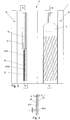
- the in the Figures 2 and 3 illustrated printing station 21 includes two mirror images of each other arranged pressure means 24, 25 for the sake of clarity in the FIG. 3 only one in two with the Print station 21 printable cylindrical objects 6 shown, in contrast, are in the FIG. 2 both arranged opposite to the printing station 21 and rotatably mounted cylindrical objects 6 shown.
- Each printing device 24, 25 comprises by way of example in each case two printing heads 22, 23, each of which has a strip-like shape and on whose cylindrical object 6 facing end face 26, 27 an exemplary nozzle row 28, 29 is formed.
- Each of the rows of nozzles 28, 29 comprises several, preferably in the same pitch or spacing along an extension axis 30, exemplified as nozzles 31 formed Farbdosieriana.
- Each of the nozzles 31 in the nozzle rows 28, 29, as shown in the FIGS. 4 . 6 and 8th are shown in section, is exemplarily individually controlled and formed in the illustrated embodiment for dispensing drops of ink.
- the two print heads 22, 23 are designed to deliver a first color, in particular the color cyan.
- further printing stations 32, 33 for dispensing a second or third color, in particular the color magenta and the color yellow (yellow) are formed.
- a printed image can be produced by a combination of differently colored ink drops which are dispensed onto the object 6 at the respective printing stations 21, 32, 33.
- more than three printing stations are provided in order to apply a larger number of colors, especially white as at least partially applied primer for the printing and / or a transparent topcoat for the carried out printing on the article 6.
- the respective printheads for dispensing a plurality of colors in particular the colors cyan, magenta and yellow, formed so that a printing of an object can be done in a single printing operation.
- a resolution of a printed image that is to say a minimum distance between the center points of adjacently arranged ink droplets in different spatial directions, can be influenced in different ways.
- each nozzle 31 of each print head 22, 23 can be driven at a predetermined frequency and can deliver drops of ink onto the peripheral surface of the object 6 at the predetermined frequency.
- the frequency determines the resolution in the circumferential direction. At a low rotational speed results in a high resolution in the circumferential direction, at high rotational speed results in a low resolution in the circumferential direction.
- a resolution for the printed image in a spatial direction parallel to the axis of rotation 5 is determined based on a print head 22 or 23 exclusively by the pitch of the nozzles 31 along the extension axis 30 of the respective print head 22, 23, as long as during the execution of the printing process no translational displacement of the respective Printhead 22, 23 along the axis of rotation 5 takes place. In this case, an annular application of the ink drops takes place on the peripheral surface of the article 6.
- the respective printing device 24, 25 is set in a suitable manner.
- the two printing heads 22, 23 of the respective printing device 24, 25 each associated with an electric drive 34, 35, which is electrically connected to a control device 36, respectively.
- the drive 34, 35 is an example of an electric motor, the drive shaft, not shown, with a rotatable and stationary in the as a print head carrier Serving pressure device 24, 25 mounted threaded spindle 37, 38 is connected.
- non-visible lock nut which is designed to implement a rotational movement of the threaded spindle 37, 38 in a translational movement of the respective print head 22, 23.
- 25 sliding guide surfaces 39, 40, 41, and 42 are provided, which enable a slide-movable and rotationally fixed mounting of the print heads 22, 23 on the printing device 24, 25.
- the control device 36 is designed for an independent control of the electrical drives 34, 35, so that the translational position of the print heads 22, 23 along the extension axis 30 can be adjusted freely.
- the print heads 22, 23 for generating a helical print track is indicated by the parallel and equidistant lines on the object 6, positioned by means of adjusting means serving as drives 34, 35 to each other such that the in the FIG. 4 shown nozzles 31 of the adjacent print heads 22, 23 are each on the parallel and mutually equidistant lines.
- Such an adjustment and synchronized use of the printheads 22, 23 can achieve a doubling of the resolution for the print image over a use of only one printhead 22 or 23 in a helical printing operation.
- the spacing of the lines depends on the desired resolution, the number of revolutions of the object 6 during the printing process with respect to the printheads 22, 23 and the diameter of the object 6.
- the print heads 22, 23 can be arranged offset by half the pitch t to each other and remain stationary during the simple rotation of the article 6.
- a further increase in the resolution can be achieved if the object 6 opposite to the two printheads 22, 23 performs several revolutions and the printheads 22, 23 during the rotational movement of the article 6 for performing the printing operation synchronously shifted along the extension axis 30, as a result a helical shape for a trace of pressure points, which are discharged from a nozzle 31 on the peripheral surface of the article 6, is achieved, in which the successively generated pressure traces of the individual nozzles are applied to the object 6 far less than a pitch t apart.
- the synchronous displacement of the printheads 22, 23 during the printing operation is selected so that a slope of the track of printing dots during one revolution of the object corresponds to a value obtained by dividing the pitch t of the nozzles 31 of a printhead 22 or 23 along the axis of extent 30 corresponds to an integer value.
- the two print heads 22, 23 with the respective drives 34, 35 are exemplarily set such that they along the track of Pressure points are arranged offset to one another such that they lie on mutually parallel and equidistant lines and that this position of the print heads 22, 23 is also maintained during the execution of the printing operation.
- the two print heads 22, 23 during the execution of a printing operation not only be moved synchronously to the extension axis but also be moved relative to each other.
- it may be provided to print the peripheral surface of the article 6 with different resolutions.
- both the relative position of the print heads 22, 23 along the extension axis 30 and a change in the rotational speed of the object 6 and / or a drive frequency for the control of the print heads 22, 23 may be provided.
- an increase in resolution for the print image in the circumferential direction can be achieved by reducing the rotation speed for the object 6 while maintaining the drive frequency for driving the print heads 22, 23 and / or the drive frequency for driving the print heads 22, 23 is increased.
- the printing device 24, 25 connected to the control device 36 is adjusted in response to the detection of printing errors in the generated print image by the inspection system in the workstation 14 for compensation of these printing errors at the next article to be printed .
- the two print heads 22, 23 are positioned relative to one another in such a way that a nozzle 31 of one of the print heads 22, 23 can be used to deliver a clogged nozzle 31 of the other print head 22, 23.
- the intact nozzle 31 does not necessarily have to be arranged on the same track of pressure points, in particular a helical path, like the defective nozzle 31, even a slight offset which is smaller than the pitch t may possibly be acceptable.
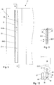
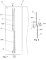
- FIGS. 4 and 5 is shown as a printing of a high-resolution object 6 in the direction of the extension axis 30 is made, whose extent along the extension axis 30 is greater than a corresponding extent of the print heads 22, 23.
- the printing process begins by way of example with a positioning of the two print heads 22, 23 in a lower starting position according to FIG FIG. 3 in which the print heads 22, 23 are arranged in accordance with the slope of the intended spiral pressure taking into account the desired resolution. Starting from this positioning, the print heads 22, 23 are moved synchronously to one another during the execution of the printing process along the extension axis 30 and the object 6 is rotated about the rotation axis 5 until the entire peripheral surface of the object 6 has been moved past the print heads 22, 23 and with Color could be provided.
- a helical printing of the peripheral surface of the article 6 is provided with a resolution along the extension axis 30, which is greater than the pitch t of the nozzles 31 to the printheads 22, 23.
- a multiple rotation of the article 6 with respect to the print heads 22, 23 is provided, during which the print heads 22, 23 are moved synchronously with each other along the extension axis 30 to produce the desired helical shape for the print tracks.
- the last nozzle 31 of the printhead 22 arranged as an example below would be arranged at the pitch t with respect to the first nozzle 31 of the printhead 23 arranged by way of example above, this would result in an offset of the print tracks of the adjacent print heads relative to the desired pitch for the helical printing of the object 6 22, 23 by the amount ds.
- the two Printheads 22, 23 are shifted by a resolution-dependent and diameter-dependent amount relative to each other, so that the amount ds disappears.
- seamless printing of the peripheral surface of the article 6 can be realized.
- a functional module 43 is arranged opposite the respective printing device 24, 25.
- the functional module 43 comprises a cleaning station 44 and a drying station 45, which by way of example on a common, rotatable about a perpendicular to the plane of the FIGS. 9 and 10 aligned rotational axis 46 mounted pivot receptacle 47 are mounted.
- the cleaning station 44 is equipped with an absorbent material, not shown, which can receive a large amount of dye, in particular ink, discharged from the print heads 22, 23 during the execution of a cleaning cycle.
- the workpiece rotary table 3 is controlled such that the respective workpiece holders 4 in the in the FIG. 1a illustrated intermediate position between two workstations 9 to 17 are arranged so that no interfering objects between the print heads 22, 23 and the respective cleaning station 44 are arranged.
- the pivot receptacle 47 is pivoted about the pivot axis 46, so that the cleaning station 44 is removed from the print head 22 or 23 and the drying station 45 reaches the print head 22 or 23 opposite position.
- the drying station 44 is at the drying station 44 to an array of light sources not shown, in particular light-emitting diodes. These light sources are designed to emit light of a predeterminable intensity and wavelength, these properties being adapted to the properties of the ink or ink to be hardened, which are dispensed from the respective print heads 22, 23 onto the object.
- a further workstation in particular the workstation 15, is equipped with a further printing station 48, which is responsible for applying a closed or selective, in particular transparent, topcoat to the peripheral surface of the object 6, in particular to the printing stations 21 , 32 and 33 printed areas, are formed and which has the same structure as one of these printing stations 21, 32, 33.
- the in the FIG. 11 illustrated printing station 50 is provided for a multi-color printing of the article 6 in a printing operation and has for this purpose three printheads 51, 52 and 53, each having three nozzle strips 54, 55 and 56. Each of the three nozzle strips 54, 55 and 56 is provided for the discharge of a color, in particular from the group cyan, magenta and yellow.
- Each of the print heads 51, 52, and 53 can be positioned in the same way along the extension axis 30 by means of an associated drive 57, 58, 59 and a respective associated threaded spindle 60, 61, 62, as for the printing stations 21, 32, 33 the case is.
- the arrangement of printing heads 51, 52, and 53 of the printing station 50 by means of a drive 63, which comprises a transmission device, not shown, relative to the axis of rotation 5 of the workpiece holder 4 can be tilted.
- the tilting direction is selected such that a distance from the print heads 51, 52 and 53 relative to the object 6 remains at least substantially constant.
- a drive 64 is provided with a gear device not shown in detail, which allows a displacement of the print heads in the radial direction to keep a controlled or regulated adjustment of a radial distance between the print heads 51, 52 and 53 and the object 6 at least largely constant.
- the drives 63 and 64 can be provided in the same way also at the printing stations 21, 32 and 33, if there is a controlled or controlled adaptation to different geometries of objects 6 is required.
- the cleaning station 66 together with the drying station 67 is accommodated on a movably mounted carriage 68.
- the cleaning station 66 has a receptacle, not shown, which is provided at an upper, the printheads 22, 23 facing edge region with a circumferential elastic sealing means 69.
- the carriage 68 is designed for carrying out two mutually perpendicular translational movements 70, 71 and for this purpose with drive means, not shown, for example, electric or pneumatic drives equipped.
- the translational movement 70 which is preferably carried out transversely to the axis of rotation 2 of the workpiece turntable 3, serves to selectively clean the cleaning station 66 or the drying station 67 below and opposite to the printheads 22, 23 to be arranged.
- the translational movement 71 which is preferably carried out parallel to the rotation axis 2 of the workpiece turntable 3, serves to bring the cleaning station 66 into sealing contact with the print heads 22, 23. This allows the desired cleaning cycle to be carried out.
- the workpiece rotary table 3 is controlled such that the respective workpiece holders 4 in the in FIG. 1a represented intermediate position between two work stations 9 to 17 are arranged so that no interfering objects between the Druccköpfen 22, 23 and the respective cleaning station 66 are arranged.
- the cleaning station 66 is removed from the printheads by means of the translatory movements 70 and 71 such that the drying station 67 reaches a position opposite the printhead 22, 23 and activates ink applied by the printheads 22, 23 to the object 6 , hardened or dried.
- a translational movement of the object to be printed in particular provided parallel to its axis of rotation.
- a rotation of the print heads around the stationary or translationally moving object is provided around.
Landscapes
- Engineering & Computer Science (AREA)
- Manufacturing & Machinery (AREA)
- Ink Jet (AREA)
Claims (13)
- Imprimante avec un bâti de machine, au niveau duquel une table ronde de pièce (3) est logée mobile en rotation, avec une unité d'entraînement associée à la table ronde de pièce (3) pour un positionnement rotatif, en particulier librement prédéfinissable, de la table ronde de pièce (3) ainsi qu'avec des logements de pièce (4) pour la réception d'objets (6) à imprimer, dans laquelle les logements de pièce (4) dépassent de la table ronde de pièce (3) dans la direction radiale et sont logés respectivement mobiles en rotation au niveau de la table ronde de pièce (3), ainsi qu'avec des moyens d'entraînement pour les logements de pièce (4) et avec au moins un dispositif d'impression (21, 32, 33; 50) logé mobile en particulier dans au moins une direction spatiale relativement mobile par rapport à la table ronde de pièce (3), dans laquelle le dispositif d'impression (21, 32, 33; 50) est réalisé pour l'impression d'une surface circonférentielle de l'objet (6) et comprend au moins deux têtes d'impression (22, 23 ; 51, 52, 53), qui présentent respectivement au moins un agencement en rangée d'éléments de dosage de couleur (31), en particulier buses de couleur, qui sont réalisés respectivement pour une distribution individuelle prédéfinissable de couleur sur l'objet (6), dans laquelle au moins une des têtes d'impression (22, 23 ; 51, 52, 53) est agencée mobile le long d'un axe d'extension (30) des éléments de dosage de couleur (31) au niveau d'un support de tête d'impression (21, 32, 33 ; 50) et dans laquelle un dispositif de réglage (34, 35 ; 57, 58, 59) à commande électrique est associé à la tête d'impression (22, 23 ; 51, 52, 53) logée mobile pour un réglage d'une position relative par rapport à l'au moins une autre tête d'impression (22, 23 ; 51, 52, 53), caractérisée en ce que le dispositif d'impression est réalisé pour la réalisation du procédé selon l'une quelconque des revendications 11 à 13.
- Imprimante selon la revendication 1, caractérisée en ce que l'au moins une autre tête d'impression (22, 23 ; 51, 52, 53), en particulier toutes les autres têtes d'impression (22, 23; 51, 52, 53), est reliée à un dispositif de réglage (34, 35 ; 57, 58, 59) à commande électrique et agencée mobile le long de l'axe d'extension (30) des éléments de dosage de couleur (31) au niveau du support de tête d'impression (21, 32, 33 ; 50).
- Imprimante selon la revendication 1 ou 2, caractérisée en ce que les têtes d'impression (22, 23; 51, 52, 53) sont orientées parallèlement l'une à l'autre et sont agencées transversalement à l'axe d'extension (30) des éléments de dosage de couleur (31) de manière directement adjacente, en particulier coulissante de façon contiguë.
- Imprimante selon l'une quelconque des revendications précédentes, caractérisée en ce que les têtes d'impression (22, 23 ; 51, 52, 53) sont réglables au moyen de l'au moins un dispositif de réglage (34, 35 ; 57, 58, 59) entre une première position de fonctionnement, dans laquelle les éléments de dosage de couleur (31) de têtes d'impression (22, 23 ; 51, 52, 53) adjacentes sont agencés sans chevauchement transversalement à l'axe d'extension (30), et une deuxième position de fonctionnement, dans laquelle un chevauchement d'éléments de dosage de couleur (31) de têtes d'impression (22, 23 ; 51, 52, 53) adjacentes est présent transversalement à l'axe d'extension (30).
- Imprimante selon l'une quelconque des revendications précédentes, caractérisée en ce qu'au moins une tête d'impression (22, 23; 51, 52, 53) comprend au moins deux rangées d'éléments de dosage de couleur (31) orientées parallèlement à l'axe d'extension (30), réalisées en particulier en tant que buses d'encre.
- Imprimante selon l'une quelconque des revendications précédentes, caractérisée en ce que les éléments de dosage de couleur (31) sont agencés le long de l'axe d'extension (30) en un pas prédéfinissable (t) et que le dispositif de réglage (34, 35 ; 57, 58, 59) est réalisé pour un positionnement de la tête d'impression (22, 23 ; 51, 52, 53) avec une précision de positionnement, qui est inférieure, de préférence inférieure à 50 pour cent, de manière préférée inférieure à 25 pour cent, de manière particulièrement préférée inférieure à 10 pour cent, en particulier inférieure à deux pour cent, du pas (t) des éléments de dosage de couleur (31) le long de l'axe d'extension (30).
- Imprimante selon l'une quelconque des revendications précédentes, caractérisée en ce qu'au moins deux groupes de têtes d'impression (22, 23 ; 51, 52, 53) logés relativement mobiles l'un par rapport à l'autre sont associés au support de tête d'impression (21, 32, 33 ; 50), dans laquelle chaque groupe de têtes d'impression (22, 23; 51, 52, 53) comprend au moins une, en particulier deux, tête d'impression (22, 23 ; 51, 52, 53).
- Imprimante selon l'une quelconque des revendications précédentes, caractérisée en ce qu'une station de séchage (45 ; 67) agencée en face des têtes d'impression (22, 23; 51, 52, 53) est associée au support de tête d'impression (21, 32, 33 ; 50), pour permettre suite à l'application de couleur un séchage de la couleur appliquée.
- Imprimante selon la revendication 8, caractérisée en ce que la station de séchage (45) est couplée à une station de nettoyage (44) pour les têtes d'impression (22, 23 ; 51, 52, 53) et logée relativement mobile au niveau du support de tête d'impression (21, 32, 33; 50) de sorte qu'un séchage de l'application de couleur sur les objets (6) ou un nettoyage des têtes d'impression (22, 23 ; 51, 52, 53) devienne possible au choix.
- Imprimante selon la revendication 1, caractérisée en ce que les logements de pièce (4) sont réalisés en tant que broches pour la réception d'objets (6) en forme de douille et/ou qu'un dispositif d'entraînement propre pour l'introduction d'un mouvement de rotation librement prédéfinissable par rapport à la table ronde de pièce (3) est associé à chaque broche et/ou que les logements de pièce (4) sont réalisés avec un dispositif de chauffage pour un chauffage des objets (6) qui y sont reçus.
- Procédé de fonctionnement d'un dispositif d'impression, qui comprend plusieurs têtes d'impression (22, 23; 51, 52, 53) orientées parallèlement l'une à l'autre et relativement mobiles l'une par rapport à l'autre de manière électrique, dans lequel un dispositif de réglage (34, 35 ; 57, 58, 59) pour l'introduction d'un mouvement relatif par rapport à au moins une autre tête d'impression (22, 23; 51, 52, 53) est associé à au moins une des têtes d'impression et dans lequel au moins un logement de pièce (4) est prévu pour un logement mobile en rotation d'un objet (6) à imprimer au niveau de sa surface circonférentielle, avec les étapes de : placement d'un objet (6) sur le logement de pièce (4), réalisation d'un mouvement relatif entre au moins deux têtes d'impression (22, 23 ; 51, 52, 53) pour influencer une résolution axiale d'une image imprimée à appliquer sur la surface circonférentielle de l'objet (6), rotation de l'objet (6) au moyen du logement de pièce (4) autour d'un axe de rotation (5), qui est orienté parallèlement à un axe d'extension (30) d'éléments de dosage de couleur (31) des têtes d'impression (22, 23 ; 51, 52, 53) de sorte que la surface circonférentielle passe les têtes d'impression (22, 23 ; 51, 52, 53), distribution de couleur sur la surface circonférentielle de l'objet (6) par une commande prédéfinie des éléments de dosage de couleur (31), caractérisé en ce qu'une vitesse de rotation du logement de pièce (4) est détectée et un débit de distribution pour une distribution de couleur par les éléments de dosage de couleur (31) est adapté à la vitesse de rotation déterminée.
- Procédé selon la revendication 11, caractérisé en ce qu'il est procédé à un mouvement synchrone des têtes d'impression (22, 23 ; 51, 52, 53) le long de l'axe de rotation (5) au moyen des dispositifs de réglage (34, 35 ; 57, 58, 59) pendant la rotation de l'objet et/ou qu'un mouvement relatif des têtes d'impression (22, 23; 51, 52, 53) parallèlement à l'axe d'extension (30) est réalisé au moyen des dispositifs de réglage (34, 35 ; 57, 58, 59) pendant la rotation de l'objet (6) pour procéder à une compensation d'erreurs d'impression.
- Procédé selon l'une quelconque des revendications 11 ou 12, caractérisé en ce qu'une zone non plane de la surface circonférentielle de l'objet (6) est utilisée comme référence pour une opération d'impression et qu'une impression, de préférence exclusive, de la zone non plane est réalisée.
Priority Applications (6)
| Application Number | Priority Date | Filing Date | Title |
|---|---|---|---|
| EP13004852.3A EP2860036B1 (fr) | 2013-10-09 | 2013-10-09 | Dispositif d'impression, imprimante et procédé de fonctionnement d'un dispositif d'impression |
| PL13004852T PL2860036T3 (pl) | 2013-10-09 | 2013-10-09 | Urządzenie drukujące, maszyna drukarska i sposób eksploatacji urządzenia drukującego |
| ES13004852T ES2768283T3 (es) | 2013-10-09 | 2013-10-09 | Equipo de impresión, máquina de impresión y procedimiento para el funcionamiento de un equipo de impresión |
| EP14000308.8A EP2868477B1 (fr) | 2013-10-09 | 2014-01-28 | Presse pour l'impression de corps creux ouverts au moins sur un côté et procédé de fonctionnement d'une presse |
| PL14000308T PL2868477T3 (pl) | 2013-10-09 | 2014-01-28 | Maszyna drukarska do zadrukowywania korpusów wydrążonych, otwartych przynajmniej z jednej strony i sposób eksploatacji maszyny drukarskiej |
| ES14000308.8T ES2661382T3 (es) | 2013-10-09 | 2014-01-28 | Impresora para imprimir cuerpos huecos abiertos al menos por un lado y procedimiento para hacer funcionar una impresora |
Applications Claiming Priority (1)
| Application Number | Priority Date | Filing Date | Title |
|---|---|---|---|
| EP13004852.3A EP2860036B1 (fr) | 2013-10-09 | 2013-10-09 | Dispositif d'impression, imprimante et procédé de fonctionnement d'un dispositif d'impression |
Publications (2)
| Publication Number | Publication Date |
|---|---|
| EP2860036A1 EP2860036A1 (fr) | 2015-04-15 |
| EP2860036B1 true EP2860036B1 (fr) | 2019-12-04 |
Family
ID=49354422
Family Applications (2)
| Application Number | Title | Priority Date | Filing Date |
|---|---|---|---|
| EP13004852.3A Active EP2860036B1 (fr) | 2013-10-09 | 2013-10-09 | Dispositif d'impression, imprimante et procédé de fonctionnement d'un dispositif d'impression |
| EP14000308.8A Active EP2868477B1 (fr) | 2013-10-09 | 2014-01-28 | Presse pour l'impression de corps creux ouverts au moins sur un côté et procédé de fonctionnement d'une presse |
Family Applications After (1)
| Application Number | Title | Priority Date | Filing Date |
|---|---|---|---|
| EP14000308.8A Active EP2868477B1 (fr) | 2013-10-09 | 2014-01-28 | Presse pour l'impression de corps creux ouverts au moins sur un côté et procédé de fonctionnement d'une presse |
Country Status (3)
| Country | Link |
|---|---|
| EP (2) | EP2860036B1 (fr) |
| ES (2) | ES2768283T3 (fr) |
| PL (2) | PL2860036T3 (fr) |
Families Citing this family (17)
| Publication number | Priority date | Publication date | Assignee | Title |
|---|---|---|---|---|
| DE102014225256A1 (de) | 2014-12-09 | 2016-06-09 | Krones Ag | Verfahren und Vorrichtung für den Tintenstrahldruck auf Behälter |
| EP3088189B1 (fr) | 2015-04-30 | 2020-11-18 | HINTERKOPF GmbH | Dispositif d'impression et procédé d'impression d'un objet d'impression |
| DE102015215224A1 (de) * | 2015-08-10 | 2017-02-16 | Krones Ag | Behälterbehandlungsmaschine und Verfahren zur Bedruckung von Behältern |
| DE102015215227A1 (de) * | 2015-08-10 | 2017-02-16 | Krones Ag | Behälterbehandlungsmaschine und Verfahren zur Bedruckung von Behältern |
| EP3344463A1 (fr) * | 2015-08-31 | 2018-07-11 | The Procter and Gamble Company | Appareil à mouvement parallèle pour déposer une substance sur des articles |
| JP2018532614A (ja) * | 2015-08-31 | 2018-11-08 | ザ プロクター アンド ギャンブル カンパニー | 物品上に物質を堆積させるための平行動作の方法 |
| DE202015007209U1 (de) | 2015-10-16 | 2015-11-11 | Hinterkopf Gmbh | Druckmaschine zur Bedruckung von hülsenförmigen Werkstücken |
| DE102016107087A1 (de) * | 2016-04-18 | 2017-10-19 | Till Gmbh | Verfahren und Vorrichtung zum digitalen Bedrucken von 3-dimensionalen Objekten |
| IT201600098327A1 (it) * | 2016-09-30 | 2018-03-30 | Omso Officina Macchine Per Stampa Su Oggetti Spa | Macchina per la stampa a getto d'inchiostro di oggetti tridimensionali, in particolare di oggetti tubolari |
| ES2737953T3 (es) | 2017-01-17 | 2020-01-17 | Hinterkopf Gmbh | Pieza en bruto de lata y procedimiento de mecanizado para un cuerpo hueco |
| DE102017215433A1 (de) * | 2017-09-04 | 2019-04-04 | Krones Ag | Direktdruckmaschine zum Aufbringen einer Druckschicht auf Behälter |
| ES2823252T3 (es) | 2017-10-17 | 2021-05-06 | Hinterkopf Gmbh | Impresora digital de mesa circular y mecanismo de impresión |
| NL2020542B1 (nl) * | 2018-03-07 | 2019-09-13 | B A T Holding B V | Printinrichting alsmede werkwijze voor het printen op een manteloppervlak van een rotatiesymmetrisch voorwerp |
| ES2813055T3 (es) * | 2018-03-15 | 2021-03-22 | Hinterkopf Gmbh | Equipo de revestimiento y procedimiento para el revestimiento de cuerpos huecos cilíndricos |
| CN111806097A (zh) * | 2020-07-21 | 2020-10-23 | 北京美科艺数码科技发展有限公司 | 一种喷墨打印装置及其翻面模式打印方法 |
| IT202100011804A1 (it) * | 2021-05-07 | 2022-11-07 | Quantix Digital S R L | Macchina da stampa digitale a getto di inchiostro |
| CN115027143B (zh) * | 2022-06-24 | 2025-03-11 | 王功庆 | 一种圆柱体侧表面uv印刷设备 |
Citations (2)
| Publication number | Priority date | Publication date | Assignee | Title |
|---|---|---|---|---|
| CH695555A5 (de) * | 2002-04-04 | 2006-06-30 | Faes Ag | Druckverfahren und Druckmaschine für dreidimensionale Druckobjekte. |
| WO2014076704A1 (fr) * | 2012-11-15 | 2014-05-22 | Velox-Puredigital Ltd. | Procédé et système d'impression |
Family Cites Families (13)
| Publication number | Priority date | Publication date | Assignee | Title |
|---|---|---|---|---|
| US6754551B1 (en) * | 2000-06-29 | 2004-06-22 | Printar Ltd. | Jet print apparatus and method for printed circuit board manufacturing |
| GB2376920A (en) | 2001-06-27 | 2002-12-31 | Inca Digital Printers Ltd | Inkjet printing on a three-dimensional object including relative movement of a printhead and the object during printing about a rotational axis |
| WO2005025873A2 (fr) * | 2003-09-17 | 2005-03-24 | Jemtex Ink Jet Printing Ltd. | Procede et appareil d'impression d'informations selectionnees sur des bouteilles |
| EP2094496B1 (fr) * | 2006-11-28 | 2012-06-27 | Xjet Ltd. | Methode d'impression par jet d'encre |
| FR2927838B1 (fr) * | 2008-02-22 | 2011-04-08 | Ceradrop | Dispositif de support de tetes d'impression. |
| DE102009020702B4 (de) * | 2009-05-11 | 2011-09-15 | Khs Gmbh | Drucksystem zum Bedrucken von Flaschen oder dergleichen Behältern sowie Druckvorrichtung oder -maschine mit einem solchen Drucksystem |
| FR2961127B1 (fr) * | 2010-06-11 | 2013-02-08 | Jean Pierre Rousselet | Machine d'impression sur objets de forme cylindrique |
| DK2471665T3 (da) * | 2010-12-30 | 2013-05-06 | Alltec Angewandte Laserlicht Technologie Gmbh | Markerings- og/eller scanningshoved, -indretning og -fremgangsmåde |
| JP5891602B2 (ja) * | 2011-04-28 | 2016-03-23 | 東洋製罐株式会社 | インクジェット印刷装置及びこれを用いたシームレス缶の印刷方法 |
| EP2580061B1 (fr) * | 2011-09-02 | 2019-09-04 | KHS GmbH | Dispositif de traitement d'emballages et unité de retenue et de centrage pour emballages |
| ES2638267T3 (es) | 2011-09-28 | 2017-10-19 | Hinterkopf Gmbh | Dispositivo de procesamiento |
| FR2985683B1 (fr) * | 2012-01-16 | 2014-02-28 | Jean Luc Perret | Machine d'impression sur articles en trois dimensions et procede d'impression |
| DE102012005046A1 (de) * | 2012-03-15 | 2013-09-19 | Till Gmbh | Verfahren zum Feststellen von Fehlern in der Ausrichtung von Druckbildern und zur Durchführung des Verfahrens eingerichtete Druckstation |
-
2013
- 2013-10-09 EP EP13004852.3A patent/EP2860036B1/fr active Active
- 2013-10-09 PL PL13004852T patent/PL2860036T3/pl unknown
- 2013-10-09 ES ES13004852T patent/ES2768283T3/es active Active
-
2014
- 2014-01-28 PL PL14000308T patent/PL2868477T3/pl unknown
- 2014-01-28 ES ES14000308.8T patent/ES2661382T3/es active Active
- 2014-01-28 EP EP14000308.8A patent/EP2868477B1/fr active Active
Patent Citations (2)
| Publication number | Priority date | Publication date | Assignee | Title |
|---|---|---|---|---|
| CH695555A5 (de) * | 2002-04-04 | 2006-06-30 | Faes Ag | Druckverfahren und Druckmaschine für dreidimensionale Druckobjekte. |
| WO2014076704A1 (fr) * | 2012-11-15 | 2014-05-22 | Velox-Puredigital Ltd. | Procédé et système d'impression |
Also Published As
| Publication number | Publication date |
|---|---|
| PL2868477T3 (pl) | 2018-06-29 |
| EP2860036A1 (fr) | 2015-04-15 |
| PL2860036T3 (pl) | 2020-08-24 |
| ES2768283T3 (es) | 2020-06-22 |
| ES2661382T3 (es) | 2018-03-28 |
| EP2868477B1 (fr) | 2017-12-20 |
| EP2868477A1 (fr) | 2015-05-06 |
Similar Documents
| Publication | Publication Date | Title |
|---|---|---|
| EP2860036B1 (fr) | Dispositif d'impression, imprimante et procédé de fonctionnement d'un dispositif d'impression | |
| EP3218195B1 (fr) | Dispositif d'impression et procédé pour l'impression de récipients | |
| EP3473446B1 (fr) | Machine d'impression numérique à table ronde et imprimante | |
| EP2152519B2 (fr) | Dispositif et procédé pour décorer des contenants par impression | |
| DE102009058212B4 (de) | Verfahren zum Betreiben einer Anlage zum Bedrucken von Behältern | |
| EP3337667B1 (fr) | Machine d'impression directe et procédé pour effectuer une impression directe sur des contenants | |
| EP2459385B1 (fr) | Systeme servant a imprimer des contenants | |
| DE102007050490A1 (de) | Vorrichtung und Verfahren zum Bedrucken von Behältern | |
| EP3110626B1 (fr) | Procédure pour aligner des ajustages relatifs de têtes d'impression et imprimante | |
| DE102009058222B4 (de) | Anlage zum Bedrucken von Behältern mit Einspannvorrichtungen mit eigenem Drehantrieb | |
| DE102006001223A1 (de) | Vorrichtung zum Bedrucken von Flaschen oder dergleichen Behälter | |
| EP2479037A1 (fr) | Dispositif et procédé destinés à l'impression de récipients | |
| EP1554121A2 (fr) | Dispositif de traitement de surface de pieces | |
| WO2007121835A1 (fr) | Procédé et dispositif pour l'impression de récipients | |
| DE202006000270U1 (de) | Vorrichtung zum Bedrucken von Flaschen o.dgl. Behälter | |
| EP0215389A2 (fr) | Procédé d'impression et de marquage pour éléments de construction | |
| DE102016013317B4 (de) | Verfahren zum Herstellen eines dreidimensionalen Formgegenstands und Vorrichtung zur Durchführung des Verfahrens | |
| EP3157753B1 (fr) | Procédé et dispositif d'impression de corps creux | |
| EP3956126B1 (fr) | Procédé de fabrication d'au moins une couche solide sur un support pouvant tourner autour d'un axe de rotation | |
| EP3088189B1 (fr) | Dispositif d'impression et procédé d'impression d'un objet d'impression | |
| DE10127659A1 (de) | Verfahren und Vorrichtung zum Bedrucken eines Objektes | |
| EP4401988B1 (fr) | Machine d'impression comprenant au moins une tête d'impression | |
| DE102014205163A1 (de) | Verfahren zum Betrieb zumindest dreier Druckköpfe einer Druckmaschine | |
| DE202006021181U1 (de) | Vorrichtung zum Bedrucken von Flaschen oder dergleichen Behälter | |
| WO2023222386A1 (fr) | Système de traitement permettant la mise en œuvre d'un processus sur une pièce, et procédé permettant la mise en œuvre d'un processus sur la pièce |
Legal Events
| Date | Code | Title | Description |
|---|---|---|---|
| PUAI | Public reference made under article 153(3) epc to a published international application that has entered the european phase |
Free format text: ORIGINAL CODE: 0009012 |
|
| 17P | Request for examination filed |
Effective date: 20131009 |
|
| AK | Designated contracting states |
Kind code of ref document: A1 Designated state(s): AL AT BE BG CH CY CZ DE DK EE ES FI FR GB GR HR HU IE IS IT LI LT LU LV MC MK MT NL NO PL PT RO RS SE SI SK SM TR |
|
| AX | Request for extension of the european patent |
Extension state: BA ME |
|
| R17P | Request for examination filed (corrected) |
Effective date: 20151012 |
|
| RBV | Designated contracting states (corrected) |
Designated state(s): AL AT BE BG CH CY CZ DE DK EE ES FI FR GB GR HR HU IE IS IT LI LT LU LV MC MK MT NL NO PL PT RO RS SE SI SK SM TR |
|
| STAA | Information on the status of an ep patent application or granted ep patent |
Free format text: STATUS: EXAMINATION IS IN PROGRESS |
|
| 17Q | First examination report despatched |
Effective date: 20190102 |
|
| REG | Reference to a national code |
Ref country code: DE Ref legal event code: R079 Ref document number: 502013013992 Country of ref document: DE Free format text: PREVIOUS MAIN CLASS: B41J0003407000 Ipc: B41J0002165000 |
|
| GRAP | Despatch of communication of intention to grant a patent |
Free format text: ORIGINAL CODE: EPIDOSNIGR1 |
|
| STAA | Information on the status of an ep patent application or granted ep patent |
Free format text: STATUS: GRANT OF PATENT IS INTENDED |
|
| RIC1 | Information provided on ipc code assigned before grant |
Ipc: B41J 25/00 20060101ALI20190621BHEP Ipc: B41J 3/407 20060101ALI20190621BHEP Ipc: B41J 3/54 20060101ALI20190621BHEP Ipc: B41J 2/165 20060101AFI20190621BHEP |
|
| INTG | Intention to grant announced |
Effective date: 20190710 |
|
| RIN1 | Information on inventor provided before grant (corrected) |
Inventor name: OSSWALD, STEFFEN Inventor name: FRANK, MARTIN Inventor name: WEBER, JOACHIM Inventor name: SCHULZ, JOACHIM Inventor name: DREXLER, STEFAN |
|
| GRAS | Grant fee paid |
Free format text: ORIGINAL CODE: EPIDOSNIGR3 |
|
| GRAA | (expected) grant |
Free format text: ORIGINAL CODE: 0009210 |
|
| STAA | Information on the status of an ep patent application or granted ep patent |
Free format text: STATUS: THE PATENT HAS BEEN GRANTED |
|
| AK | Designated contracting states |
Kind code of ref document: B1 Designated state(s): AL AT BE BG CH CY CZ DE DK EE ES FI FR GB GR HR HU IE IS IT LI LT LU LV MC MK MT NL NO PL PT RO RS SE SI SK SM TR |
|
| REG | Reference to a national code |
Ref country code: GB Ref legal event code: FG4D Free format text: NOT ENGLISH |
|
| REG | Reference to a national code |
Ref country code: CH Ref legal event code: EP Ref country code: CH Ref legal event code: NV Representative=s name: TROESCH SCHEIDEGGER WERNER AG, CH |
|
| REG | Reference to a national code |
Ref country code: AT Ref legal event code: REF Ref document number: 1208894 Country of ref document: AT Kind code of ref document: T Effective date: 20191215 |
|
| REG | Reference to a national code |
Ref country code: DE Ref legal event code: R096 Ref document number: 502013013992 Country of ref document: DE |
|
| REG | Reference to a national code |
Ref country code: IE Ref legal event code: FG4D Free format text: LANGUAGE OF EP DOCUMENT: GERMAN |
|
| REG | Reference to a national code |
Ref country code: NL Ref legal event code: MP Effective date: 20191204 |
|
| REG | Reference to a national code |
Ref country code: LT Ref legal event code: MG4D |
|
| PG25 | Lapsed in a contracting state [announced via postgrant information from national office to epo] |
Ref country code: LV Free format text: LAPSE BECAUSE OF FAILURE TO SUBMIT A TRANSLATION OF THE DESCRIPTION OR TO PAY THE FEE WITHIN THE PRESCRIBED TIME-LIMIT Effective date: 20191204 Ref country code: SE Free format text: LAPSE BECAUSE OF FAILURE TO SUBMIT A TRANSLATION OF THE DESCRIPTION OR TO PAY THE FEE WITHIN THE PRESCRIBED TIME-LIMIT Effective date: 20191204 Ref country code: BG Free format text: LAPSE BECAUSE OF FAILURE TO SUBMIT A TRANSLATION OF THE DESCRIPTION OR TO PAY THE FEE WITHIN THE PRESCRIBED TIME-LIMIT Effective date: 20200304 Ref country code: FI Free format text: LAPSE BECAUSE OF FAILURE TO SUBMIT A TRANSLATION OF THE DESCRIPTION OR TO PAY THE FEE WITHIN THE PRESCRIBED TIME-LIMIT Effective date: 20191204 Ref country code: GR Free format text: LAPSE BECAUSE OF FAILURE TO SUBMIT A TRANSLATION OF THE DESCRIPTION OR TO PAY THE FEE WITHIN THE PRESCRIBED TIME-LIMIT Effective date: 20200305 Ref country code: NO Free format text: LAPSE BECAUSE OF FAILURE TO SUBMIT A TRANSLATION OF THE DESCRIPTION OR TO PAY THE FEE WITHIN THE PRESCRIBED TIME-LIMIT Effective date: 20200304 Ref country code: LT Free format text: LAPSE BECAUSE OF FAILURE TO SUBMIT A TRANSLATION OF THE DESCRIPTION OR TO PAY THE FEE WITHIN THE PRESCRIBED TIME-LIMIT Effective date: 20191204 |
|
| PG25 | Lapsed in a contracting state [announced via postgrant information from national office to epo] |
Ref country code: HR Free format text: LAPSE BECAUSE OF FAILURE TO SUBMIT A TRANSLATION OF THE DESCRIPTION OR TO PAY THE FEE WITHIN THE PRESCRIBED TIME-LIMIT Effective date: 20191204 Ref country code: RS Free format text: LAPSE BECAUSE OF FAILURE TO SUBMIT A TRANSLATION OF THE DESCRIPTION OR TO PAY THE FEE WITHIN THE PRESCRIBED TIME-LIMIT Effective date: 20191204 |
|
| REG | Reference to a national code |
Ref country code: ES Ref legal event code: FG2A Ref document number: 2768283 Country of ref document: ES Kind code of ref document: T3 Effective date: 20200622 |
|
| PG25 | Lapsed in a contracting state [announced via postgrant information from national office to epo] |
Ref country code: AL Free format text: LAPSE BECAUSE OF FAILURE TO SUBMIT A TRANSLATION OF THE DESCRIPTION OR TO PAY THE FEE WITHIN THE PRESCRIBED TIME-LIMIT Effective date: 20191204 |
|
| PG25 | Lapsed in a contracting state [announced via postgrant information from national office to epo] |
Ref country code: EE Free format text: LAPSE BECAUSE OF FAILURE TO SUBMIT A TRANSLATION OF THE DESCRIPTION OR TO PAY THE FEE WITHIN THE PRESCRIBED TIME-LIMIT Effective date: 20191204 Ref country code: NL Free format text: LAPSE BECAUSE OF FAILURE TO SUBMIT A TRANSLATION OF THE DESCRIPTION OR TO PAY THE FEE WITHIN THE PRESCRIBED TIME-LIMIT Effective date: 20191204 Ref country code: RO Free format text: LAPSE BECAUSE OF FAILURE TO SUBMIT A TRANSLATION OF THE DESCRIPTION OR TO PAY THE FEE WITHIN THE PRESCRIBED TIME-LIMIT Effective date: 20191204 Ref country code: PT Free format text: LAPSE BECAUSE OF FAILURE TO SUBMIT A TRANSLATION OF THE DESCRIPTION OR TO PAY THE FEE WITHIN THE PRESCRIBED TIME-LIMIT Effective date: 20200429 |
|
| PG25 | Lapsed in a contracting state [announced via postgrant information from national office to epo] |
Ref country code: SM Free format text: LAPSE BECAUSE OF FAILURE TO SUBMIT A TRANSLATION OF THE DESCRIPTION OR TO PAY THE FEE WITHIN THE PRESCRIBED TIME-LIMIT Effective date: 20191204 Ref country code: SK Free format text: LAPSE BECAUSE OF FAILURE TO SUBMIT A TRANSLATION OF THE DESCRIPTION OR TO PAY THE FEE WITHIN THE PRESCRIBED TIME-LIMIT Effective date: 20191204 Ref country code: IS Free format text: LAPSE BECAUSE OF FAILURE TO SUBMIT A TRANSLATION OF THE DESCRIPTION OR TO PAY THE FEE WITHIN THE PRESCRIBED TIME-LIMIT Effective date: 20200404 |
|
| REG | Reference to a national code |
Ref country code: DE Ref legal event code: R097 Ref document number: 502013013992 Country of ref document: DE |
|
| PLBE | No opposition filed within time limit |
Free format text: ORIGINAL CODE: 0009261 |
|
| STAA | Information on the status of an ep patent application or granted ep patent |
Free format text: STATUS: NO OPPOSITION FILED WITHIN TIME LIMIT |
|
| PG25 | Lapsed in a contracting state [announced via postgrant information from national office to epo] |
Ref country code: DK Free format text: LAPSE BECAUSE OF FAILURE TO SUBMIT A TRANSLATION OF THE DESCRIPTION OR TO PAY THE FEE WITHIN THE PRESCRIBED TIME-LIMIT Effective date: 20191204 |
|
| 26N | No opposition filed |
Effective date: 20200907 |
|
| PG25 | Lapsed in a contracting state [announced via postgrant information from national office to epo] |
Ref country code: SI Free format text: LAPSE BECAUSE OF FAILURE TO SUBMIT A TRANSLATION OF THE DESCRIPTION OR TO PAY THE FEE WITHIN THE PRESCRIBED TIME-LIMIT Effective date: 20191204 |
|
| PG25 | Lapsed in a contracting state [announced via postgrant information from national office to epo] |
Ref country code: LU Free format text: LAPSE BECAUSE OF NON-PAYMENT OF DUE FEES Effective date: 20201009 Ref country code: MC Free format text: LAPSE BECAUSE OF FAILURE TO SUBMIT A TRANSLATION OF THE DESCRIPTION OR TO PAY THE FEE WITHIN THE PRESCRIBED TIME-LIMIT Effective date: 20191204 |
|
| REG | Reference to a national code |
Ref country code: BE Ref legal event code: MM Effective date: 20201031 |
|
| PG25 | Lapsed in a contracting state [announced via postgrant information from national office to epo] |
Ref country code: BE Free format text: LAPSE BECAUSE OF NON-PAYMENT OF DUE FEES Effective date: 20201031 |
|
| PG25 | Lapsed in a contracting state [announced via postgrant information from national office to epo] |
Ref country code: IE Free format text: LAPSE BECAUSE OF NON-PAYMENT OF DUE FEES Effective date: 20201009 |
|
| PG25 | Lapsed in a contracting state [announced via postgrant information from national office to epo] |
Ref country code: TR Free format text: LAPSE BECAUSE OF FAILURE TO SUBMIT A TRANSLATION OF THE DESCRIPTION OR TO PAY THE FEE WITHIN THE PRESCRIBED TIME-LIMIT Effective date: 20191204 Ref country code: MT Free format text: LAPSE BECAUSE OF FAILURE TO SUBMIT A TRANSLATION OF THE DESCRIPTION OR TO PAY THE FEE WITHIN THE PRESCRIBED TIME-LIMIT Effective date: 20191204 Ref country code: CY Free format text: LAPSE BECAUSE OF FAILURE TO SUBMIT A TRANSLATION OF THE DESCRIPTION OR TO PAY THE FEE WITHIN THE PRESCRIBED TIME-LIMIT Effective date: 20191204 |
|
| PG25 | Lapsed in a contracting state [announced via postgrant information from national office to epo] |
Ref country code: MK Free format text: LAPSE BECAUSE OF FAILURE TO SUBMIT A TRANSLATION OF THE DESCRIPTION OR TO PAY THE FEE WITHIN THE PRESCRIBED TIME-LIMIT Effective date: 20191204 |
|
| P01 | Opt-out of the competence of the unified patent court (upc) registered |
Effective date: 20230530 |
|
| PGFP | Annual fee paid to national office [announced via postgrant information from national office to epo] |
Ref country code: PL Payment date: 20250924 Year of fee payment: 13 |
|
| PGFP | Annual fee paid to national office [announced via postgrant information from national office to epo] |
Ref country code: CZ Payment date: 20250926 Year of fee payment: 13 |
|
| REG | Reference to a national code |
Ref country code: CH Ref legal event code: U11 Free format text: ST27 STATUS EVENT CODE: U-0-0-U10-U11 (AS PROVIDED BY THE NATIONAL OFFICE) Effective date: 20251101 |
|
| PGFP | Annual fee paid to national office [announced via postgrant information from national office to epo] |
Ref country code: DE Payment date: 20250815 Year of fee payment: 13 |
|
| PGFP | Annual fee paid to national office [announced via postgrant information from national office to epo] |
Ref country code: GB Payment date: 20251024 Year of fee payment: 13 |
|
| PGFP | Annual fee paid to national office [announced via postgrant information from national office to epo] |
Ref country code: AT Payment date: 20251021 Year of fee payment: 13 |
|
| PGFP | Annual fee paid to national office [announced via postgrant information from national office to epo] |
Ref country code: IT Payment date: 20251031 Year of fee payment: 13 |
|
| PGFP | Annual fee paid to national office [announced via postgrant information from national office to epo] |
Ref country code: FR Payment date: 20251024 Year of fee payment: 13 |
|
| PGFP | Annual fee paid to national office [announced via postgrant information from national office to epo] |
Ref country code: CH Payment date: 20251101 Year of fee payment: 13 |
|
| PGFP | Annual fee paid to national office [announced via postgrant information from national office to epo] |
Ref country code: ES Payment date: 20251114 Year of fee payment: 13 |