EP4401988B1 - Machine d'impression comprenant au moins une tête d'impression - Google Patents
Machine d'impression comprenant au moins une tête d'impression Download PDFInfo
- Publication number
- EP4401988B1 EP4401988B1 EP23703766.8A EP23703766A EP4401988B1 EP 4401988 B1 EP4401988 B1 EP 4401988B1 EP 23703766 A EP23703766 A EP 23703766A EP 4401988 B1 EP4401988 B1 EP 4401988B1
- Authority
- EP
- European Patent Office
- Prior art keywords
- printing
- relevant
- print head
- article
- Prior art date
- Legal status (The legal status is an assumption and is not a legal conclusion. Google has not performed a legal analysis and makes no representation as to the accuracy of the status listed.)
- Active
Links
Images

Classifications
-
- B—PERFORMING OPERATIONS; TRANSPORTING
- B41—PRINTING; LINING MACHINES; TYPEWRITERS; STAMPS
- B41J—TYPEWRITERS; SELECTIVE PRINTING MECHANISMS, i.e. MECHANISMS PRINTING OTHERWISE THAN FROM A FORME; CORRECTION OF TYPOGRAPHICAL ERRORS
- B41J3/00—Typewriters or selective printing or marking mechanisms characterised by the purpose for which they are constructed
- B41J3/407—Typewriters or selective printing or marking mechanisms characterised by the purpose for which they are constructed for marking on special material
- B41J3/4073—Printing on three-dimensional objects not being in sheet or web form, e.g. spherical or cubic objects
- B41J3/40733—Printing on cylindrical or rotationally symmetrical objects, e. g. on bottles
-
- B—PERFORMING OPERATIONS; TRANSPORTING
- B41—PRINTING; LINING MACHINES; TYPEWRITERS; STAMPS
- B41J—TYPEWRITERS; SELECTIVE PRINTING MECHANISMS, i.e. MECHANISMS PRINTING OTHERWISE THAN FROM A FORME; CORRECTION OF TYPOGRAPHICAL ERRORS
- B41J2/00—Typewriters or selective printing mechanisms characterised by the printing or marking process for which they are designed
- B41J2/005—Typewriters or selective printing mechanisms characterised by the printing or marking process for which they are designed characterised by bringing liquid or particles selectively into contact with a printing material
- B41J2/01—Ink jet
- B41J2/135—Nozzles
- B41J2/145—Arrangement thereof
-
- B—PERFORMING OPERATIONS; TRANSPORTING
- B41—PRINTING; LINING MACHINES; TYPEWRITERS; STAMPS
- B41J—TYPEWRITERS; SELECTIVE PRINTING MECHANISMS, i.e. MECHANISMS PRINTING OTHERWISE THAN FROM A FORME; CORRECTION OF TYPOGRAPHICAL ERRORS
- B41J25/00—Actions or mechanisms not otherwise provided for
- B41J25/001—Mechanisms for bodily moving print heads or carriages parallel to the paper surface
-
- B—PERFORMING OPERATIONS; TRANSPORTING
- B41—PRINTING; LINING MACHINES; TYPEWRITERS; STAMPS
- B41J—TYPEWRITERS; SELECTIVE PRINTING MECHANISMS, i.e. MECHANISMS PRINTING OTHERWISE THAN FROM A FORME; CORRECTION OF TYPOGRAPHICAL ERRORS
- B41J25/00—Actions or mechanisms not otherwise provided for
- B41J25/001—Mechanisms for bodily moving print heads or carriages parallel to the paper surface
- B41J25/003—Mechanisms for bodily moving print heads or carriages parallel to the paper surface for changing the angle between a print element array axis and the printing line, e.g. for dot density changes
-
- B—PERFORMING OPERATIONS; TRANSPORTING
- B41—PRINTING; LINING MACHINES; TYPEWRITERS; STAMPS
- B41J—TYPEWRITERS; SELECTIVE PRINTING MECHANISMS, i.e. MECHANISMS PRINTING OTHERWISE THAN FROM A FORME; CORRECTION OF TYPOGRAPHICAL ERRORS
- B41J25/00—Actions or mechanisms not otherwise provided for
- B41J25/304—Bodily-movable mechanisms for print heads or carriages movable towards or from paper surface
- B41J25/316—Bodily-movable mechanisms for print heads or carriages movable towards or from paper surface with tilting motion mechanisms relative to paper surface
-
- B—PERFORMING OPERATIONS; TRANSPORTING
- B41—PRINTING; LINING MACHINES; TYPEWRITERS; STAMPS
- B41J—TYPEWRITERS; SELECTIVE PRINTING MECHANISMS, i.e. MECHANISMS PRINTING OTHERWISE THAN FROM A FORME; CORRECTION OF TYPOGRAPHICAL ERRORS
- B41J3/00—Typewriters or selective printing or marking mechanisms characterised by the purpose for which they are constructed
- B41J3/407—Typewriters or selective printing or marking mechanisms characterised by the purpose for which they are constructed for marking on special material
- B41J3/4073—Printing on three-dimensional objects not being in sheet or web form, e.g. spherical or cubic objects
- B41J3/40731—Holders for objects, e. g. holders specially adapted to the shape of the object to be printed or adapted to hold several objects
-
- B—PERFORMING OPERATIONS; TRANSPORTING
- B41—PRINTING; LINING MACHINES; TYPEWRITERS; STAMPS
- B41J—TYPEWRITERS; SELECTIVE PRINTING MECHANISMS, i.e. MECHANISMS PRINTING OTHERWISE THAN FROM A FORME; CORRECTION OF TYPOGRAPHICAL ERRORS
- B41J3/00—Typewriters or selective printing or marking mechanisms characterised by the purpose for which they are constructed
- B41J3/54—Typewriters or selective printing or marking mechanisms characterised by the purpose for which they are constructed with two or more sets of type or printing elements
- B41J3/543—Typewriters or selective printing or marking mechanisms characterised by the purpose for which they are constructed with two or more sets of type or printing elements with multiple inkjet print heads
Definitions
- a print beam structure for a printing device for use in printing on an outer surface of an object wherein the Object comprises at least one cylindrical section, the print bar structure comprising: a body defining a print zone for receiving the object to be printed, the print zone having a central axis; and a plurality of radially spaced mounting formations provided adjacent to the print zone for mounting a plurality of print heads, the print heads being operatively disposed within the print zone to form an arc within the print zone for applying liquid from a liquid source to the object along a print axis that is at least transverse to the central axis of the print zone, the print bar structure comprising a plurality of print banks, each print bank comprising mounting formations for one or more print heads, and each print bank extending along an axis that is oriented obliquely to the central axis, or the arc defined by the print heads extending along an axis that is oriented obliquely to the central axis
- a liquid dispensing device comprising: a dispensing unit that dispenses liquid from nozzles to a medium; a rotation mechanism that relatively rotates the medium and the ejection unit about a rotation axis direction that crosses a ejection direction of the liquid; and a control unit that controls an ejection frequency of the liquid according to a relative moving distance between the medium and the ejection unit per unit time.
- a printing device comprising: n print heads arranged along a first direction, each print head being in fluid communication with at least two different inks; a print medium arranged opposite the print head, the print medium comprising s print areas divided along the first direction such that each print area is configured for printing by a print head, the print medium being configured to rotate about a rotation axis; a motion controller controlling the movement of the print heads and the movement of the print medium; and a print driver controlling the Controls printing of the print heads, where s and n are positive integers greater than 1.
- a transport unit places and transports a recording medium on a conveying surface having a curvature in a conveying direction of the recording medium.
- a nozzle surface on which a nozzle opening for ejecting ink is arranged, is provided opposite the conveying surface.
- a recording head has a mounting member to which the recording head is mounted, with a plurality of mounting members being provided at different positions in the conveying direction.
- the ink droplets ejected by the print head in question must therefore travel a significantly longer distance.
- the ink droplets in question must be larger than when printing on other printing materials, i.e., when printing on hollow bodies made of glass, the ink droplets each contain a comparatively larger amount of ink. This means that these ink droplets must be subjected to greater kinetic energy in order to overcome the air resistance along their flight path.
- the increased energy required by the print head in question means that the print head in question can only be designed with a very limited printing width, whereby this printing width is currently commercially available print heads is typically 70 mm.
- a further difficulty in creating a print image with a print length exceeding this print width is that, due to their housing, these print heads cannot be aligned in such a way that their respective print widths would seamlessly complement each other to create a print length exceeding the individual print width. Instead, such print heads must be arranged offset from one another in different printing planes. This requires tracking of the respective print position of the respective print head for distortion-free and precisely registered printing of the outer surface of a conical rotary body.
- a plurality of different printing planes are provided with respect to the surface of the article in question to be printed, with the print nozzles arranged in the different printing planes each ejecting inks of different colors, e.g. inks in the process colors cyan, magenta, yellow and black. Since these printing planes each intersect the longitudinal axis of the article to be printed, immediately adjacent printing planes form a V-formation.
- a series of several articles that are identical in their respective geometry are printed in the printing press, wherein their geometry has a large spread within the respective tolerances.
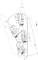
- FIG. 1 several, e.g. two different printing levels 04 are shown, wherein two print heads 01 of the illustrated arrangement arranged in the same printing level 04 are not placed seamlessly next to one another, but are arranged in a row in the relevant printing level 04, spaced from one another by a mounting gap 06.
- the two printing levels 04 each intersect the longitudinal axis X2 of the rotating body 02 to be printed, and thus the two rows of print heads 01 form a V-formation in this arrangement.
- this holder 12 of the print head 01 in question is preferably designed to be movable such that the print head 01 in question executes a rotational movement about its transverse axis Y1 and/or about its longitudinal axis X1 in addition to its vertical axis Z1.
- the rotational mobility of the respective print head 01 around its vertical axis Z1 and a controlled tracking of the printing position of the respective print head 01 ensures that at least one print head 01 in the printing process is always arranged perpendicular to the printing surface of the conically shaped article 02 in question, even if this article 02 has a runout error on the order of magnitude of, for example, ⁇ 2 mm and/or the tolerances of its geometry have a wide range.
- a plurality of different printing planes 04 are provided, wherein the print nozzles 07 arranged in the different printing planes 04 each eject the same inks or inks of different colors, wherein immediately adjacent printing planes 04 form a V-formation.
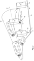
- Fig. 2 shows, in a perspective view, schematically and in a highly simplified manner, a first exemplary embodiment of the holder holding the print head 01 in question, which holder is designed, for example, in such a way that the print head 01 in question executes at least one rotational movement about its vertical axis Z1.
- a rigid plate 12 which is rigidly connected to the print head 01 in question is arranged in the printing plane 04 of the print head 01 in question, wherein in the case of a plurality of print heads 01 arranged in the same printing plane 04, these print heads 01, which are preferably arranged in a row, are rigidly connected to the same rigid plate 12.
- the relevant coupling 16 has, for example, a ball 17 or a cylinder 18 at its respective connection point with the relevant rigid plate 12 and/or with the relevant actuator 13.
- the actuators 13 are, for example, each designed as a linear motor, wherein each of these actuators 13 is designed to execute a particularly bidirectional travel path.
- the three actuators 13 of this first embodiment are controlled by a control unit which, for example, controls the printing process.
- This control unit is designed such that, during an ongoing printing process, it tracks or at least can track the respective printing position of the relevant print head 01 in accordance with the geometric requirements of the article 02 to be printed, i.e. depending on its surface geometry.
Landscapes
- Engineering & Computer Science (AREA)
- Manufacturing & Machinery (AREA)
- Ink Jet (AREA)
Claims (9)
- Machine à imprimer avec au moins une tête d'impression (01), dans laquelle la tête d'impression (01) concernée est réalisée de manière à imprimer une surface d'un article (02) en rotation dans le processus d'impression dans un procédé d'impression à jet d'encre, dans laquelle une largeur d'impression (08) de la tête d'impression (01) concernée s'étend respectivement sur une partie d'une longueur (L02) de l'article (02) à imprimer, dans laquelle la partie concernée s'étend respectivement longitudinalement par rapport à un axe longitudinal (X2) de l'article (02) à imprimer, dans laquelle un système de coordonnées orthogonal tridimensionnel fixé à la tête d'impression disposé avec son origine dans un centre de gravité (09) de la tête d'impression (01) concernée présente un axe longitudinal (X1) et un axe transversal (Y1) et un axe vertical (Z1), dans laquelle l'axe longitudinal (X1) de la tête d'impression (01) concernée s'étend parallèlement à la largeur d'impression (08) de cette tête d'impression (01), dans laquelle plusieurs têtes d'impression (01) imprimant respectivement la surface de l'article (02) concerné dans un procédé d'impression à jet d'encre sont prévues, dans laquelle ces têtes d'impression (01) sont disposées sur une rangée longitudinalement par rapport à l'axe longitudinal (X2) de l'article (02) à imprimer, dans laquelle une direction respective de l'encre éjectée par les buses d'impression (07) respectives de ces têtes d'impression (01) et l'axe longitudinal (X2) de l'article (02) à imprimer se trouvent dans un même plan d'impression (04) et la direction respective de l'encre éjectée par les buses d'impression (07) respectives de ces têtes d'impression (01) est orientée respectivement perpendiculairement à la surface à imprimer de l'article (02) concerné, dans laquelle plusieurs plans d'impression (04) différents les uns des autres sont prévus par rapport à la surface à imprimer de l'article (02) concerné, dans laquelle les plans d'impression (04) immédiatement adjacents réalisent une formation en V, dans laquelle une unité de commande est prévue, dans laquelle cette unité de commande est réalisée de telle sorte que dans un processus d'impression en cours elle réajuste ou au moins peut réajuster une position d'impression respective de la tête d'impression (01) concernée en fonction d'une géométrie de surface de l'article (02) à imprimer, dans laquelle un élément de retenue retenant la tête d'impression (01) concernée est prévu, caractérisée en ce que l'élément de retenue de la tête d'impression (01) concernée est réalisé de manière mobile, de telle sorte que la tête d'impression (01) concernée effectue un mouvement rotatif au moins autour de son axe vertical (Z1), dans laquelle l'élément de retenue modifiant la tête d'impression (01) concernée dans sa position dans l'espace présente un premier mécanisme de réglage (21), avec lequel l'au moins une tête d'impression (01) est déplaçable le long de son axe transversal (Y1), dans laquelle cet élément de retenue présente un deuxième mécanisme de réglage (22), avec lequel l'au moins une tête d'impression (01) peut être amenée en rotation autour de son axe vertical (Z1), et dans laquelle cet élément de retenue présente un troisième mécanisme de réglage (23), avec lequel l'au moins une tête d'impression (01) peut être amenée en rotation autour de son axe longitudinal (X1).
- Machine à imprimer selon la revendication 1, caractérisée en ce que l'élément de retenue de la tête d'impression (01) concernée est réalisé de manière mobile, de telle sorte que la tête d'impression (01) concernée effectue, excepté autour de son axe vertical (Z1), un mouvement rotatif respectivement également autour de son axe transversal (Y1) et/ou autour de son axe longitudinal (X1).
- Machine à imprimer selon la revendication 1 ou 2, caractérisée en ce que les têtes d'impression (01) sont disposées dans le processus d'impression respectivement perpendiculairement à la surface à imprimer de l'article (02) concerné, dans laquelle un plan de coupe longitudinale (04) s'étendant à travers la tête d'impression (01) concernée coupe un axe de rotation (03) de l'article (02) concerné, dans laquelle l'axe de rotation (03) de l'article (02) concerné est l'axe longitudinal (X2) de celui-ci.
- Machine à imprimer selon la revendication 1 ou 2 ou 3, caractérisée en ce que chacune des têtes d'impression (01) est disposée respectivement à une distance comprise entre 1 mm et moins de 8 mm de la surface à imprimer de l'article (02) concerné.
- Machine à imprimer selon la revendication 1 ou 2 ou 3 ou 4, caractérisée en ce que chacune des têtes d'impression (01) présente au moins une rangée de buses d'impression (07) juxtaposées, dans laquelle une longueur de la rangée concernée de buses d'impression (07) définit la largeur d'impression (08) de la tête d'impression (01) concernée.
- Machine à imprimer selon la revendication 1 ou 2 ou 3 ou 4 ou 5, caractérisée en ce que l'article (02) à imprimer est retenu dans un dispositif de retenue faisant partie de la machine à imprimer, dans laquelle un système de coordonnées orthogonal tridimensionnel fixé à l'article disposé avec son origine dans un centre de gravité (11) de l'article (02) concerné présente l'axe longitudinal (X2) de l'article (02) concerné et un axe transversal (Y2) et un axe vertical (Z2), dans laquelle le dispositif de retenue de l'article (02) concerné est réalisé de manière mobile, de telle sorte que l'article (02) concerné effectue respectivement un mouvement rotatif autour de son axe transversal (Y2) et/ou autour de son axe vertical (Z2).
- Machine à imprimer selon la revendication 1 ou 2 ou 3 ou 4 ou 5 ou 6, caractérisée en ce que les têtes d'impression (01) disposées dans le même plan d'impression (04) peuvent être déplacées respectivement ensemble par les mécanismes de réglage (21 ; 22 ; 23) concernés le long de leur axe transversal (Y1) respectif et/ou peuvent être amenées en rotation autour de leur axe longitudinal (X1) respectif et/ou autour de leur axe vertical (Z1) respectif.
- Machine à imprimer selon la revendication 1 ou 2 ou 3 ou 4 ou 5 ou 6 ou 7, caractérisée en ce que les mécanismes de réglage (21 ; 22 ; 23) modifiant la tête d'impression (01) concernée dans sa position dans l'espace sont actionnés ou au moins peuvent être actionnés électriquement.
- Machine à imprimer selon la revendication 1 ou 2 ou 3 ou 4 ou 5 ou 6 ou 7 ou 8, caractérisée en ce que les mécanismes de réglage (21 ; 22 ; 23) modifiant la tête d'impression (01) concernée dans sa position dans l'espace sont commandés par l'unité de commande.
Applications Claiming Priority (2)
| Application Number | Priority Date | Filing Date | Title |
|---|---|---|---|
| DE102022111172.5A DE102022111172A1 (de) | 2022-05-05 | 2022-05-05 | Druckmaschine mit mindestens einem Druckkopf |
| PCT/EP2023/052834 WO2023213452A1 (fr) | 2022-05-05 | 2023-02-06 | Machine d'impression comprenant au moins une tête d'impression |
Publications (2)
| Publication Number | Publication Date |
|---|---|
| EP4401988A1 EP4401988A1 (fr) | 2024-07-24 |
| EP4401988B1 true EP4401988B1 (fr) | 2025-04-16 |
Family
ID=85199197
Family Applications (1)
| Application Number | Title | Priority Date | Filing Date |
|---|---|---|---|
| EP23703766.8A Active EP4401988B1 (fr) | 2022-05-05 | 2023-02-06 | Machine d'impression comprenant au moins une tête d'impression |
Country Status (4)
| Country | Link |
|---|---|
| US (1) | US12202284B1 (fr) |
| EP (1) | EP4401988B1 (fr) |
| DE (1) | DE102022111172A1 (fr) |
| WO (1) | WO2023213452A1 (fr) |
Citations (2)
| Publication number | Priority date | Publication date | Assignee | Title |
|---|---|---|---|---|
| WO2022207529A1 (fr) * | 2021-03-30 | 2022-10-06 | Quantix Digital S.R.L. | Machine d'impression numérique à jet d'encre pour impression sur des substrats cylindriques |
| WO2022234006A1 (fr) * | 2021-05-07 | 2022-11-10 | Quantix Digital S.R.L. | Machine d'impression numérique à jet d'encre |
Family Cites Families (13)
| Publication number | Priority date | Publication date | Assignee | Title |
|---|---|---|---|---|
| JP4419015B2 (ja) | 2004-03-04 | 2010-02-24 | リコープリンティングシステムズ株式会社 | インクジェット塗布方法及び装置 |
| JP2009184121A (ja) | 2008-02-01 | 2009-08-20 | Mimaki Engineering Co Ltd | 3次元プリンタ |
| EP2631077A1 (fr) | 2012-02-21 | 2013-08-28 | Dip Tech. Ltd. | Système d'impression |
| FR3009235B1 (fr) | 2013-07-31 | 2016-01-01 | Dubuit Mach | Machine d'impression d'un objet comportant des tetes d'impressions a jets d'encre inclinables. |
| DE102013110103A1 (de) | 2013-09-13 | 2015-03-19 | Till Gmbh | Vorrichtung zum Bedrucken von rotationsasymmetrischen Behältern |
| CN107073936B (zh) | 2014-05-20 | 2019-12-13 | 维罗斯-纯粹数字有限公司 | 打印系统及方法 |
| WO2015186592A1 (fr) | 2014-06-02 | 2015-12-10 | コニカミノルタ株式会社 | Dispositif d'enregistrement à jet d'encre |
| JP2016022665A (ja) | 2014-07-22 | 2016-02-08 | セイコーエプソン株式会社 | 液体吐出装置及び液体吐出方法 |
| GB2546968A (en) * | 2016-01-27 | 2017-08-09 | Dover Europe Sàrl | A control assembly |
| US20170253024A1 (en) | 2016-03-03 | 2017-09-07 | Inx International Ink Co. | Apparatus and method for printing on non-cylindrical surfaces having circular symmetry |
| US11207898B2 (en) | 2017-04-26 | 2021-12-28 | Pailprint (Pty) Ltd | Print bar structure, a printing apparatus, and a method of printing |
| CN111439031A (zh) | 2020-05-13 | 2020-07-24 | 苏州新锐发科技有限公司 | 打印设备及方法 |
| EP4210958A4 (fr) * | 2020-09-10 | 2024-10-16 | Ink Cups Now LLC | Système et procédé d'impression de récipient creux |
-
2022
- 2022-05-05 DE DE102022111172.5A patent/DE102022111172A1/de active Pending
-
2023
- 2023-02-06 WO PCT/EP2023/052834 patent/WO2023213452A1/fr not_active Ceased
- 2023-02-06 US US18/709,100 patent/US12202284B1/en active Active
- 2023-02-06 EP EP23703766.8A patent/EP4401988B1/fr active Active
Patent Citations (2)
| Publication number | Priority date | Publication date | Assignee | Title |
|---|---|---|---|---|
| WO2022207529A1 (fr) * | 2021-03-30 | 2022-10-06 | Quantix Digital S.R.L. | Machine d'impression numérique à jet d'encre pour impression sur des substrats cylindriques |
| WO2022234006A1 (fr) * | 2021-05-07 | 2022-11-10 | Quantix Digital S.R.L. | Machine d'impression numérique à jet d'encre |
Also Published As
| Publication number | Publication date |
|---|---|
| US12202284B1 (en) | 2025-01-21 |
| EP4401988A1 (fr) | 2024-07-24 |
| DE102022111172A1 (de) | 2023-11-09 |
| WO2023213452A1 (fr) | 2023-11-09 |
Similar Documents
| Publication | Publication Date | Title |
|---|---|---|
| EP2319699B1 (fr) | Dispositif pour imprimer un composant par un procédé d'impression numérique | |
| EP2832546B1 (fr) | Imprimante dotée d'une commande de tête d'impression | |
| DE102009058212B4 (de) | Verfahren zum Betreiben einer Anlage zum Bedrucken von Behältern | |
| EP0921008B1 (fr) | Procédé compensateur de tolérance dans une tête d'impression à jet d'encre | |
| EP3055137B1 (fr) | Machine d'impression à fonctionnement synchronisé | |
| EP3681724B1 (fr) | Machine d'impression directe pour l'application d'une couche d'impression sur des récipients | |
| EP3067210B1 (fr) | Dispositif d'impression d'une surface d'un objet | |
| DE102009058222B4 (de) | Anlage zum Bedrucken von Behältern mit Einspannvorrichtungen mit eigenem Drehantrieb | |
| DE102009033810A1 (de) | Anlage zum Bedrucken von Behältern | |
| WO2017025219A1 (fr) | Machine de traitement de contenants et procédé d'impression de contenants | |
| DE69901016T2 (de) | Verfahren und Gerät zum Drucken auf eine durchlaufende Materialbahn | |
| DE102024104484A1 (de) | Druckwerk einer Tintendruckmaschine | |
| EP4401988B1 (fr) | Machine d'impression comprenant au moins une tête d'impression | |
| EP1333987B1 (fr) | Procede et dispositif d'orientation de tetes d'impression | |
| WO2019201494A1 (fr) | Dispositif d'impression directe sur des recipients | |
| EP3720715B1 (fr) | Machine pour le traitement d'un substrat en forme de plaque comprenant une table aspirante déplaçable | |
| DE10057063C1 (de) | Druckvorrichtung | |
| EP1333986A1 (fr) | Dispositifs d'impression comportant une pluralite de tetes d'impression | |
| EP4335766A1 (fr) | Dispositif et procédé d'étiquetage d'un récipient | |
| DE102020134088A1 (de) | Druckvorrichtung | |
| DE102018204111A1 (de) | Montagevorrichtung für einen Druckkopf | |
| DE102017204660A1 (de) | Inkjetdruckkopf mit Düsen mit einer Einrichtung zur Anpassung des Austrittswinkels |
Legal Events
| Date | Code | Title | Description |
|---|---|---|---|
| STAA | Information on the status of an ep patent application or granted ep patent |
Free format text: STATUS: UNKNOWN |
|
| STAA | Information on the status of an ep patent application or granted ep patent |
Free format text: STATUS: THE INTERNATIONAL PUBLICATION HAS BEEN MADE |
|
| PUAI | Public reference made under article 153(3) epc to a published international application that has entered the european phase |
Free format text: ORIGINAL CODE: 0009012 |
|
| STAA | Information on the status of an ep patent application or granted ep patent |
Free format text: STATUS: REQUEST FOR EXAMINATION WAS MADE |
|
| 17P | Request for examination filed |
Effective date: 20240417 |
|
| AK | Designated contracting states |
Kind code of ref document: A1 Designated state(s): AL AT BE BG CH CY CZ DE DK EE ES FI FR GB GR HR HU IE IS IT LI LT LU LV MC ME MK MT NL NO PL PT RO RS SE SI SK SM TR |
|
| GRAP | Despatch of communication of intention to grant a patent |
Free format text: ORIGINAL CODE: EPIDOSNIGR1 |
|
| STAA | Information on the status of an ep patent application or granted ep patent |
Free format text: STATUS: GRANT OF PATENT IS INTENDED |
|
| DAV | Request for validation of the european patent (deleted) | ||
| DAX | Request for extension of the european patent (deleted) | ||
| INTG | Intention to grant announced |
Effective date: 20250131 |
|
| GRAS | Grant fee paid |
Free format text: ORIGINAL CODE: EPIDOSNIGR3 |
|
| GRAA | (expected) grant |
Free format text: ORIGINAL CODE: 0009210 |
|
| STAA | Information on the status of an ep patent application or granted ep patent |
Free format text: STATUS: THE PATENT HAS BEEN GRANTED |
|
| AK | Designated contracting states |
Kind code of ref document: B1 Designated state(s): AL AT BE BG CH CY CZ DE DK EE ES FI FR GB GR HR HU IE IS IT LI LT LU LV MC ME MK MT NL NO PL PT RO RS SE SI SK SM TR |
|
| REG | Reference to a national code |
Ref country code: GB Ref legal event code: FG4D Free format text: NOT ENGLISH |
|
| REG | Reference to a national code |
Ref country code: CH Ref legal event code: EP Ref country code: DE Ref legal event code: R096 Ref document number: 502023000846 Country of ref document: DE |
|
| REG | Reference to a national code |
Ref country code: IE Ref legal event code: FG4D Free format text: LANGUAGE OF EP DOCUMENT: GERMAN |
|
| REG | Reference to a national code |
Ref country code: NL Ref legal event code: MP Effective date: 20250416 |
|
| PG25 | Lapsed in a contracting state [announced via postgrant information from national office to epo] |
Ref country code: NL Free format text: LAPSE BECAUSE OF FAILURE TO SUBMIT A TRANSLATION OF THE DESCRIPTION OR TO PAY THE FEE WITHIN THE PRESCRIBED TIME-LIMIT Effective date: 20250416 |
|
| PG25 | Lapsed in a contracting state [announced via postgrant information from national office to epo] |
Ref country code: FI Free format text: LAPSE BECAUSE OF FAILURE TO SUBMIT A TRANSLATION OF THE DESCRIPTION OR TO PAY THE FEE WITHIN THE PRESCRIBED TIME-LIMIT Effective date: 20250416 Ref country code: ES Free format text: LAPSE BECAUSE OF FAILURE TO SUBMIT A TRANSLATION OF THE DESCRIPTION OR TO PAY THE FEE WITHIN THE PRESCRIBED TIME-LIMIT Effective date: 20250416 Ref country code: PT Free format text: LAPSE BECAUSE OF FAILURE TO SUBMIT A TRANSLATION OF THE DESCRIPTION OR TO PAY THE FEE WITHIN THE PRESCRIBED TIME-LIMIT Effective date: 20250818 |
|
| REG | Reference to a national code |
Ref country code: LT Ref legal event code: MG9D |
|
| PG25 | Lapsed in a contracting state [announced via postgrant information from national office to epo] |
Ref country code: GR Free format text: LAPSE BECAUSE OF FAILURE TO SUBMIT A TRANSLATION OF THE DESCRIPTION OR TO PAY THE FEE WITHIN THE PRESCRIBED TIME-LIMIT Effective date: 20250717 Ref country code: NO Free format text: LAPSE BECAUSE OF FAILURE TO SUBMIT A TRANSLATION OF THE DESCRIPTION OR TO PAY THE FEE WITHIN THE PRESCRIBED TIME-LIMIT Effective date: 20250716 |
|
| PG25 | Lapsed in a contracting state [announced via postgrant information from national office to epo] |
Ref country code: PL Free format text: LAPSE BECAUSE OF FAILURE TO SUBMIT A TRANSLATION OF THE DESCRIPTION OR TO PAY THE FEE WITHIN THE PRESCRIBED TIME-LIMIT Effective date: 20250416 |
|
| PG25 | Lapsed in a contracting state [announced via postgrant information from national office to epo] |
Ref country code: BG Free format text: LAPSE BECAUSE OF FAILURE TO SUBMIT A TRANSLATION OF THE DESCRIPTION OR TO PAY THE FEE WITHIN THE PRESCRIBED TIME-LIMIT Effective date: 20250416 |
|
| PG25 | Lapsed in a contracting state [announced via postgrant information from national office to epo] |
Ref country code: HR Free format text: LAPSE BECAUSE OF FAILURE TO SUBMIT A TRANSLATION OF THE DESCRIPTION OR TO PAY THE FEE WITHIN THE PRESCRIBED TIME-LIMIT Effective date: 20250416 |
|
| PG25 | Lapsed in a contracting state [announced via postgrant information from national office to epo] |
Ref country code: RS Free format text: LAPSE BECAUSE OF FAILURE TO SUBMIT A TRANSLATION OF THE DESCRIPTION OR TO PAY THE FEE WITHIN THE PRESCRIBED TIME-LIMIT Effective date: 20250716 |
|
| PG25 | Lapsed in a contracting state [announced via postgrant information from national office to epo] |
Ref country code: IS Free format text: LAPSE BECAUSE OF FAILURE TO SUBMIT A TRANSLATION OF THE DESCRIPTION OR TO PAY THE FEE WITHIN THE PRESCRIBED TIME-LIMIT Effective date: 20250816 |
|
| PG25 | Lapsed in a contracting state [announced via postgrant information from national office to epo] |
Ref country code: LV Free format text: LAPSE BECAUSE OF FAILURE TO SUBMIT A TRANSLATION OF THE DESCRIPTION OR TO PAY THE FEE WITHIN THE PRESCRIBED TIME-LIMIT Effective date: 20250416 |
|
| PG25 | Lapsed in a contracting state [announced via postgrant information from national office to epo] |
Ref country code: DK Free format text: LAPSE BECAUSE OF FAILURE TO SUBMIT A TRANSLATION OF THE DESCRIPTION OR TO PAY THE FEE WITHIN THE PRESCRIBED TIME-LIMIT Effective date: 20250416 Ref country code: SM Free format text: LAPSE BECAUSE OF FAILURE TO SUBMIT A TRANSLATION OF THE DESCRIPTION OR TO PAY THE FEE WITHIN THE PRESCRIBED TIME-LIMIT Effective date: 20250416 |
|
| REG | Reference to a national code |
Ref country code: DE Ref legal event code: R097 Ref document number: 502023000846 Country of ref document: DE |
|
| PG25 | Lapsed in a contracting state [announced via postgrant information from national office to epo] |
Ref country code: CZ Free format text: LAPSE BECAUSE OF FAILURE TO SUBMIT A TRANSLATION OF THE DESCRIPTION OR TO PAY THE FEE WITHIN THE PRESCRIBED TIME-LIMIT Effective date: 20250416 |
|
| PG25 | Lapsed in a contracting state [announced via postgrant information from national office to epo] |
Ref country code: EE Free format text: LAPSE BECAUSE OF FAILURE TO SUBMIT A TRANSLATION OF THE DESCRIPTION OR TO PAY THE FEE WITHIN THE PRESCRIBED TIME-LIMIT Effective date: 20250416 |
|
| PG25 | Lapsed in a contracting state [announced via postgrant information from national office to epo] |
Ref country code: SK Free format text: LAPSE BECAUSE OF FAILURE TO SUBMIT A TRANSLATION OF THE DESCRIPTION OR TO PAY THE FEE WITHIN THE PRESCRIBED TIME-LIMIT Effective date: 20250416 |
|
| PG25 | Lapsed in a contracting state [announced via postgrant information from national office to epo] |
Ref country code: IT Free format text: LAPSE BECAUSE OF FAILURE TO SUBMIT A TRANSLATION OF THE DESCRIPTION OR TO PAY THE FEE WITHIN THE PRESCRIBED TIME-LIMIT Effective date: 20250416 |
|
| PLBE | No opposition filed within time limit |
Free format text: ORIGINAL CODE: 0009261 |
|
| STAA | Information on the status of an ep patent application or granted ep patent |
Free format text: STATUS: NO OPPOSITION FILED WITHIN TIME LIMIT |
|
| REG | Reference to a national code |
Ref country code: CH Ref legal event code: L10 Free format text: ST27 STATUS EVENT CODE: U-0-0-L10-L00 (AS PROVIDED BY THE NATIONAL OFFICE) Effective date: 20260225 |
|
| REG | Reference to a national code |
Ref country code: CH Ref legal event code: U11 Free format text: ST27 STATUS EVENT CODE: U-0-0-U10-U11 (AS PROVIDED BY THE NATIONAL OFFICE) Effective date: 20260301 |
|
| 26N | No opposition filed |
Effective date: 20260119 |
|
| PGFP | Annual fee paid to national office [announced via postgrant information from national office to epo] |
Ref country code: DE Payment date: 20260305 Year of fee payment: 4 |
|
| PGFP | Annual fee paid to national office [announced via postgrant information from national office to epo] |
Ref country code: AT Payment date: 20260301 Year of fee payment: 4 |
|
| PGFP | Annual fee paid to national office [announced via postgrant information from national office to epo] |
Ref country code: FR Payment date: 20260225 Year of fee payment: 4 |
|
| PGFP | Annual fee paid to national office [announced via postgrant information from national office to epo] |
Ref country code: CH Payment date: 20260301 Year of fee payment: 4 |