EP2860121A1 - Etikettiervorrichtung - Google Patents
Etikettiervorrichtung Download PDFInfo
- Publication number
- EP2860121A1 EP2860121A1 EP13187653.4A EP13187653A EP2860121A1 EP 2860121 A1 EP2860121 A1 EP 2860121A1 EP 13187653 A EP13187653 A EP 13187653A EP 2860121 A1 EP2860121 A1 EP 2860121A1
- Authority
- EP
- European Patent Office
- Prior art keywords
- labels
- holding means
- web
- speed
- adhesive
- Prior art date
- Legal status (The legal status is an assumption and is not a legal conclusion. Google has not performed a legal analysis and makes no representation as to the accuracy of the status listed.)
- Granted
Links
Images

Classifications
-
- B—PERFORMING OPERATIONS; TRANSPORTING
- B65—CONVEYING; PACKING; STORING; HANDLING THIN OR FILAMENTARY MATERIAL
- B65C—LABELLING OR TAGGING MACHINES, APPARATUS, OR PROCESSES
- B65C9/00—Details of labelling machines or apparatus
- B65C9/08—Label feeding
- B65C9/18—Label feeding from strips, e.g. from rolls
- B65C9/1865—Label feeding from strips, e.g. from rolls the labels adhering on a backing strip
- B65C9/1876—Label feeding from strips, e.g. from rolls the labels adhering on a backing strip and being transferred by suction means
- B65C9/188—Label feeding from strips, e.g. from rolls the labels adhering on a backing strip and being transferred by suction means the suction means being a vacuum drum
-
- B—PERFORMING OPERATIONS; TRANSPORTING
- B65—CONVEYING; PACKING; STORING; HANDLING THIN OR FILAMENTARY MATERIAL
- B65C—LABELLING OR TAGGING MACHINES, APPARATUS, OR PROCESSES
- B65C9/00—Details of labelling machines or apparatus
- B65C9/40—Controls; Safety devices
- B65C9/42—Label feed control
Definitions
- the invention relates to a labeling device for applying labels to a material web moved at a web speed in a transport direction, comprising a label dispenser and a transfer device which takes the labels from the label dispenser by means of holding means, moves them to the material web and applies them to the material web at a transfer point.
- Labels are usually stored on carrier foils. Since there are usually no or only very small distances between the labels on the carrier films, these distances must be adapted to larger distances between the labels on the materials to be labeled if necessary. This can be achieved for example by a transfer device between label dispenser and web.
- the DE10228243B4 describes for this purpose a labeling device in which self-adhesive labels are guided transversely to the transport direction of the webs of material via a label dispenser to a conveyor belt, which sucks the labels on their non-adhesive side and this leads across the material webs.
- the label spacings are adapted when dispensing the labels on the conveyor belt by the ratio of the speed of the carrier film to the speed of the conveyor belt, wherein both the carrier belt and the conveyor belt run continuously.
- this type of adaptation is only possible if the distances of the labels on the carrier tape and on the packaging film sections do not differ significantly or many times.
- the labels are fed transversely to the transport direction, which requires a further device for applying the labels and a cyclic operation of the web.
- a vacuum drum As a transfer device between the label dispenser and the web can be dispensed with a further device for applying the labels to the web.
- a vacuum drum is in the DE3915987A1 described.
- self-adhesive labels are transferred from the carrier film with its non-adhesive side to a vacuum drum, wherein several suction positions are located on the cylindrical surface of this vacuum drum.
- the conveying speed of the carrier tape, the vacuum drum and the articles to be labeled is continuous in this invention, wherein the speed of the carrier tape is adapted to the speed of the articles to be labeled.
- the distances of the labels are predefined in this invention on the distances of the labels on the vacuum drum.
- the distance between the labels from the carrier tape to the material web can not be increased significantly or many times if the labels must be moved at the same speed as the material web to exact and proper application of the labels to reach the web material.
- the dispensing speed at high production speeds is a limiting factor since the labels can not be accelerated to the high speeds of material webs.
- the dispensing speed is limited by the high masses of the long components and the long labels.
- the present invention achieves the stated object by providing a labeling device for applying labels to a material web moved at a web speed in a transport direction, comprising a label dispenser and a transfer device which takes over the labels from the label dispenser by means of holding means, moves to the material web and arrives at a transfer point the material web applies, characterized in that the holding means of the transfer device in an orbit with variable rotational speed in and against the transport direction are movable, wherein the holding means, when they are at the transfer point, the web speed in the transport direction.
- the transfer device can take over the labels from the label dispenser without wrinkling, tearing, etc.
- the label dispenser dispenses the labels at a dispensing location at a speed in the dispensing direction and the holding means of the transfer device have the same speed and direction when they are at the Donation site.
- the speed of rotation of the holding means is variably controllable and in particular the holding means can be accelerated from a lower speed at the dispensing location to a higher speed at the transfer point, narrow spacings of the labels in the labeling device can be translated into large distances of the labels on the web by the speed control of the holding means is such that the time it takes the wrapping means to travel one full circle is the same time that the web takes to travel the distance between two applied labels.
- the transfer device is a rotating cylinder with an axis of rotation transverse to the transport direction, wherein the holding means are arranged on the lateral surface of the cylinder.
- the transfer device comprises at least one driven endless belt on which the holding means are arranged.
- the movement of the holding means in its orbit is reversible, because this makes it possible to reverse the transport direction of the web without having to turn over the label dispenser.
- the holding means are designed as a vacuum suction, preferably with adjustable vacuum force. If the labels are formed as one-sided adhesive labels, and the holding means hold the adhesive labels on their non-adhesive side, it is advantageous for a simple but reliable transfer of the labels from the transfer device to the web if the vacuum force with which the holding means are the adhesive labels is less than the adhesive force between the adhesive side of the adhesive labels and the web.
- the production of one-sided adhesive labels can be done online during the transfer of the labels by an adhesive applicator positioned to apply an adhesive on the side of the labels away from the transfer device.
- the label dispenser dispenses the labels with their longitudinal axis transversely to the transport direction, although it is difficult to achieve high dispensing speeds when dispensing oblong labels transversely to the transport direction, since the way and the time is in principle when used in cyclically operated label dispensers for the acceleration of the label is lower than when the labels are donated with their longitudinal axis in the transport direction.
- the shortest distances between the labels in the label dispenser and particularly large distances between the labels on the material web can be set when the label dispenser moves the labels cyclically, in particular on a carrier belt, to the delivery location.
- a counterpressure device opposite the transfer device in particular a rotating counterpressure roller with an axis of rotation transverse to the transport direction, is arranged at the transfer point.
- the label dispenser comprises a cutting device that cuts individual labels from a web-shaped label material.
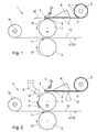
- FIGS. 1 to 3 schematically show a labeling device 1 according to the invention.
- the labeling device 1 is used for applying labels 2 to a material web 10 moved at a web speed V1 in a transport direction T1.
- the labeling device 1 comprises a label dispenser 4 and a transfer device 7 which takes over the labels 2 from the label dispenser 4 by means of holding means 8 , moved to the web 10 and applied to a transfer point 11 on the web 10.
- the holding means 8 of the transfer device 7 are movable in an orbit with variable rotational speed Vx in and counter to the transport direction T1, wherein the rotational speed Vx is controlled by a machine control, not shown, so that the holding means 8, when they are at the transfer point 11, have the web speed V1 in the transport direction T1.
- the label dispenser 4 is operated in cycles, the web 10 moves continuously with the web speed V1.
- the transfer device 7 is a rotating cylinder with a rotation axis transverse to the transport direction T1, and the holding means 8 are arranged on the lateral surface of the cylinder.
- the orbit of the holding means 8 is a circular path, and the rotational speed Vx of the holding means is given by the rotational speed of the driven, rotating cylinder.
- the movement of the cylinder and thus the holding means 8 is reversible and can take place in and counterclockwise.
- the holding means 8 are designed as vacuum suction devices, preferably with adjustable vacuum force. The supply of the vacuum 14 to the holding means 8 can take place through the interior of the cylinder.
- the label dispenser 4 has a supply roll 5 on which the - in this example - one-sided self-adhesive labels are adhesively wound with its adhesive side to a carrier tape 3.
- the carrier tape 3 with the labels 2 is supplied to the label dispenser 4.
- the labels 2 are non-adhesive labels, but there is an adhesive applicator 12 next to the transfer device 7, which applies an adhesive 15 to the side facing away from the transfer device 7 side of the labels 2.
- the labels 2 are not stored as individual labels in the supply roll 5, but as a web-shaped label material 2 '.
- the label dispenser 4 has a cutting device 13 which cuts off individual labels 2 from the web-shaped label material 2 '.
- the labels 2 are elongated labels, which are arranged with their longitudinal axis arranged transversely to the transport direction T1 at a dispensing point 6 of the label dispenser 4 in the transport direction T1. For this purpose, a correspondingly wide label dispenser 4 with a wide dispensing point 6 is required. Due to the large mass of the long components of the label dispenser 4 and the elongated labels 2, the acceleration of the labels during dispensing and thus the dispensing speed V2, but limited.
- the labels 2 are taken over by the holding means 8 of the cylindrical transfer device 7 by a label 2 at the dispensing point 6 at its non-adhesive side by means of vacuum 14th is sucked to the suction means 8 of the transfer device 7.
- the holding means 8 of the transfer device 7 be guided past the dispensing station 6 at the same speed with which the label is dispensed.
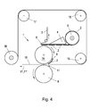
- Fig. 4 the web 10 is fed via rollers 17,18,19 in the transport direction T1 'of the transfer point 11.
- 10 labels 2 can be applied to the back of the web.
- the transfer device 7 is guided past the label dispenser with dispensing speed V2 counter to the transport direction T1 '(in dispensing direction). If a label was taken from the holding means 8, the direction of movement is reversed and the label is transferred at the transfer point in the transport direction T1 'with web speed V1 to the back of the material web.
- Fig. 5 shows a diagram of the varying speed Vx of the rotating holding means 8 over the time t for one complete revolution of the cylindrical transfer device 7.
- the section A shows the status in which the holding means 8 with the dispensing speed V2 are guided past the dispensing point 6.
- the cylinder must be accelerated to the transport speed V1 of the continuously moving material web 10, so that the label 2 can be applied with its adhesive side to the material web 10 exactly and wrinkle-free.
- This acceleration process corresponds to section B of the velocity / time diagram of Fig. 4 , The corresponding position of the holding means 8 is in Fig. 2 shown.
- the vacuum force / suction force must be able to hold the label on the holding means 8 during the acceleration process, but should be smaller than the adhesive force of the label 2, so that it can be applied to the web 10 at the transfer point 11. It is also a regulation or a position-controlled switching on and off of the intake conceivable.
- the holding means 8 When the holding means 8 reach the transfer point 11, they have already been accelerated to the transport speed V1 and constantly move at the transport speed V1, as in section C of the velocity diagram of FIG Fig. 4 you can see.
- the holding means 8 are braked by slowing the rotational speed of the cylindrical transfer device 7 back to the dispensing speed V2, as in section D of the velocity diagram of Fig. 4 you can see.
- the corresponding position of the holding means 8 is in Fig. 3 shown. All sections A, B, C, D together describe one complete revolution of the holding means 8.
- the variable speed of rotation Vx of the holding means 8 is controlled so that the time taken by the holding means 8 for one complete cycle is equal to the time which the web of material 10 is required to continue to move by the distance L between two applied labels 2,2.
- the cylindrical transfer device 7 is reversibly rotatable clockwise and counterclockwise, it is also possible to have a label 2 in the illustrated dispensing direction and as soon as it adheres to the holding means 8, the transfer device 7 to move in the opposite direction. This makes it possible to donate labels 2 even if the direction of movement T1 of the web of material 10 changes without having to invert the orientation of the label dispenser 4.
- the distances L can be changed at any time between labels 2 on the material web 10, without having to rebuild the labeling device 1 by the exchange of cylindrical transfer devices with other diameters.
- Conventional continuously running vacuum cylinders must be replaced as the label pitch changes, which of course results in a delay in the manufacturing process.
- the speed control cylindrical transfer devices 7 it is possible to install by means of the speed control cylindrical transfer devices 7 with small diameters, resulting in space and weight savings.
- the mass of the cylinder may be defined by materials such as e.g. Carbon fiber reinforced plastics, are kept very low.
- Another advantage of small diameter cylinders is that the centrifugal force acting on the labels 2 is lower at the same rotational speed on small diameter cylinders than in large diameter cylinders. As a result, less suction force is required for small cylinders to hold the labels on the holding means 8.
- the number of storable labels 2 at the same diameter of the supply roll 5 is substantially higher than labels which are arranged with its longitudinal axis parallel to the material web 10.
- the production must be interrupted less frequently for a change of the supply roll 5, which increases the efficiency of the labeling device 1.
- the transfer device 7 may comprise at least one driven endless belt, on which the holding means 8 are arranged.
- the labeling device according to the invention is particularly useful in plants for the production of bags with folded bottom used in the elongated labels for example Reinforcing a material weakening (eg Easy Open Feature) are applied or serve as a sac mouth reinforcement.
- a material weakening eg Easy Open Feature
- the labeling device can process non-adhesive labels (with the optional adhesive applicator), self-adhesive labels, as well as labels with pressure-sensitive adhesive or hotmelt.
- Different label spacings may be adjusted simply by controlling the speed of rotation of the holding means on the transfer device, depending on the requirement of the webs of material (e.g., with different repeat lengths of bag bodies).
- print marks can be used as the speed control signal of the transfer device to determine the position of the labels.
- the supply roll for the labels does not have to be positioned in the label dispenser, but may e.g. be arranged laterally next to the machine frame or installed in the machine.
Landscapes
- Labeling Devices (AREA)
Abstract
Description
- Die Erfindung betrifft eine Etikettiervorrichtung zum Aufbringen von Etiketten auf eine mit einer Bahngeschwindigkeit in einer Transportrichtung bewegten Materialbahn, umfassend einen Etikettenspender und eine Transfervorrichtung, die mittels Haltemitteln die Etiketten vom Etikettenspender übernimmt, zur Materialbahn bewegt und an einer Übergabestelle auf die Materialbahn aufbringt.
- Solche Etikettiervorrichtung werden in vielen industriellen Produktionsprozessen benötigt. Dabei stellen stetig steigende Laufgeschwindigkeiten von Produktionsanlagen immer höhere Anforderungen an die Leistung der Etikettiervorrichtungen. Insbesondere wenn die Materialbahnen kontinuierlich bei hohen Geschwindigkeiten bewegt werden und gleichzeitig Etiketten in großen Abständen auf die Materialbahnen aufgetragen werden, stoßen konventionelle Etikettiervorrichtungen an ihre Grenzen.
- Etiketten werden meist auf Trägerfolien gespeichert. Da es zwischen den Etiketten auf den Trägerfolien üblicherweise keine oder nur sehr geringe Abstände gibt, müssen diese Abstände bei Bedarf an größere Abstände zwischen den Etiketten auf den zu etikettierenden Materialien angepasst werden. Dies kann zum Beispiel durch eine Transfervorrichtung zwischen Etikettenspender und Materialbahn erreicht werden.
- Die
DE10228243B4 beschreibt dazu eine Etikettiervorrichtung, bei der selbstklebende Etiketten quer zur Transportrichtung der Materialbahnen über einen Etikettenspender an ein Transportband geführt werden, welches die Etiketten an ihrer nicht klebenden Seite ansaugt und diese quer über die Materialbahnen führt. Die Etikettenabstände werden beim Spenden der Etiketten auf das Transportband durch das Verhältnis der Geschwindigkeit der Trägerfolie zur Geschwindigkeit des Transportbandes angepasst, wobei sowohl das Trägerband als auch das Transportband kontinuierlich laufen. Diese Art der Anpassung ist jedoch nur möglich, wenn sich die Abstände der Etiketten am Trägerband und auf den Verpackungsfolienabschnitten nicht wesentlich oder um ein Vielfaches unterscheiden. Außerdem werden bei dieser bekannten Etikettiervorrichtung die Etiketten quer zur Transportrichtung zugeführt, was eine weitere Vorrichtung zum Auftragen der Etiketten und einen taktweisen Betrieb der Materialbahn erfordert. - Durch die Verwendung einer Vakuumtrommel als Transfervorrichtung zwischen dem Etikettenspender und der Materialbahn kann auf eine weitere Vorrichtung zum Auftragen der Etiketten auf die Materialbahn verzichtet werden kann. So eine Vakuumtrommel wird in der
DE3915987A1 beschrieben. Dabei werden selbsthaftende Etiketten von der Trägerfolie mit ihrer nicht klebenden Seite an eine Vakuumtrommel übergeben, wobei sich mehrere Ansaugpositionen an der zylindrischen Mantelfläche dieser Vakuumtrommel befinden. Die Fördergeschwindigkeit des Trägerbandes, der Vakuumtrommel und der zu etikettierenden Gegenstände ist bei dieser Erfindung kontinuierlich, wobei die Geschwindigkeit des Trägerbandes an die Geschwindigkeit der zu etikettierenden Gegenstände angepasst wird. Die Abstände der Etiketten sind bei dieser Erfindung über die Abstände der Etiketten auf der Vakuumtrommel vordefiniert. Größere Abstände zwischen den Etiketten auf den zu etikettierenden Materialien könnten hier nur durch größere Abstände der Etiketten auf dem Trägerband und größere Abstände der Etiketten auf der Vakuumtrommel erreicht werden. Das würde einerseits zu extrem großen Durchmessern der Etiketten-Vorratsrollen und sehr hohem Trägerbandverbrauch führen, andererseits würde eine Vergrößerung der Etikettenabstände auch den Austausch der Vakuumtrommel erforderlich machen. - Durch einen kontinuierlichen Betrieb des Etikettenspenders und der Transfervorrichtung lässt sich der Abstand zwischen den Etiketten vom Trägerband zur Materialbahn nicht wesentlich bzw. um ein Vielfaches vergrößern, wenn die Etiketten mit gleicher Geschwindigkeit wie die Materialbahn bewegt werden müssen, um exaktes und einwandfreies Auftragen der Etiketten auf dem Bahnmaterial zu erreichen.
- Bei taktweise betriebenen Etikettenspendern stellt die Spendegeschwindigkeit bei hohen Produktionsgeschwindigkeiten einen limitierenden Faktor dar, da die Etiketten nicht auf die hohen Geschwindigkeiten von Materialbahnen beschleunigt werden können. Insbesondere bei länglichen Etiketten, deren Längsachse quer zur Transportrichtung angeordnet ist und die in Transportrichtung auf die Materialbahn aufgetragen werden, ist die Spendegeschwindigkeit durch die hohen Massen der langen Bauteile und der langen Etiketten limitiert.
- Zusammenfassend können bei kontinuierlich laufenden Etikettenspendern nur geringe Abstände zwischen Etiketten auf einer Materialbahn erreicht werden, und bei diskontinuierlich laufenden Etikettenspendern können keine hohen Materialbahngeschwindigkeiten erreicht werden.
- Es ist daher die Aufgabe der Erfindung Etiketten, (insbesondere längliche Etiketten mit ihrer Längsachse quer zur Materialbahn), exakt und faltenfrei auf eine sich kontinuierlich mit hoher Geschwindigkeit bewegende Materialbahn aufzubringen, wobei die Abstände der Etiketten nach ihrem Aufbringen auf der Materialbahn wesentlich größer sind als in ihrem gespeicherten Zustand vor dem Aufbringen, insbesondere ihrem gespeicherten Zustand auf einem Trägerband.
- Die vorliegende Erfindung löst die gestellte Aufgabe durch Bereitstellen einer Etikettiervorrichtung zum Aufbringen von Etiketten auf eine mit einer Bahngeschwindigkeit in einer Transportrichtung bewegten Materialbahn, umfassend einen Etikettenspender und eine Transfervorrichtung, die mittels Haltemitteln die Etiketten vom Etikettenspender übernimmt, zur Materialbahn bewegt und an einer Übergabestelle auf die Materialbahn aufbringt, dadurch gekennzeichnet, dass die Haltemittel der Transfervorrichtung in einer Umlaufbahn mit variabler Umlaufgeschwindigkeit in und entgegen der Transportrichtung bewegbar sind, wobei die Haltemittel, wenn sie sich an der Übergabestelle befinden, die Bahngeschwindigkeit in der Transportrichtung aufweisen.
- Damit die Transfervorrichtung die Etiketten vom Etikettenspender ohne Faltenbildung, Einreißen, etc. übernehmen kann, ist vorgesehen, dass der Etikettenspender an einer Spendestelle die Etiketten mit einer Geschwindigkeit in Spenderichtung abgibt und die Haltemittel der Transfervorrichtung dieselbe Geschwindigkeit und Richtung aufweisen, wenn sie sich an der Spendestelle befinden.
- Da die Umlaufgeschwindigkeit der Haltemittel variabel steuerbar ist und insbesondere die Haltemittel von einer niedrigeren Geschwindigkeit an der Spendestelle zu einer höheren Geschwindigkeit an der Übergabestelle beschleunigt werden können, können enge Abstände der Etiketten in der Etikettiervorrichtung in große Abstände der Etiketten an der Materialbahn übersetzt werden, indem die Geschwindigkeitssteuerung der Haltemittel so erfolgt, dass die Zeit, die die Haltemittel für einen ganzen Umlauf benötigen, dieselbe Zeit ist, die die Materialbahn benötigt, um sich um den Abstand zwischen zwei aufgebrachten Etiketten weiter zu bewegen.
- In einer bevorzugten Ausführungsform ist die Transfervorrichtung ein rotierender Zylinder mit einer Drehachse quer zur Transportrichtung, wobei die Haltemittel auf der Mantelfläche des Zylinders angeordnet sind. Alternativ dazu umfasst die Transfervorrichtung zumindest ein angetriebenes Endlosband, auf dem die Haltemittel angeordnet sind.
- Bevorzugt ist die Bewegung der Haltemittel auf ihrer Umlaufbahn umkehrbar, weil dies ermöglicht, die Transportrichtung der Materialbahn umzukehren, ohne den Etikettenspender umdrehen zu müssen.
- Einen sehr schnellen und verlässlich steuerbaren Betrieb der Etikettiervorrichtung erzielt man, indem die Haltemittel als Vakuumsauger, vorzugsweise mit einstellbarer Vakuumkraft, ausgebildet sind. Wenn die Etiketten als einseitige Klebeetiketten ausgebildet sind, und die Haltemittel die Klebeetiketten an ihrer nicht klebenden Seite halten, ist es für eine einfache, aber verlässliche Übergabe der Etiketten von der Transfervorrichtung auf die Materialbahn vorteilhaft, wenn die Vakuumkraft, mit der die Haltemittel die Klebeetiketten halten, kleiner ist als die Haftkraft zwischen der Klebeseite der Klebeetiketten und der Materialbahn.
- Die Herstellung einseitiger Klebeetiketten kann online während des Transfers der Etiketten durch einen Kleberapplikator erfolgen, der so positioniert ist, dass er einen Kleber auf der von der Transfervorrichtung abgewandten Seite der Etiketten aufbringt.
- Mit der Erfindung ist es sogar möglich, dass der Etikettenspender die Etiketten mit ihrer Längsachse quer zur Transportrichtung abgibt, obwohl es prinzipiell bei taktweise betriebenen Etikettenspendern schwierig ist hohe Spendegeschwindigkeiten zu erreichen, wenn man längliche Etiketten quer zur Transportrichtung spendet, da der Weg und die Zeit für die Beschleunigung des Etikettes geringer ist, als wenn die Etiketten mit ihrer Längsachse in Transportrichtung gespendet werden.
- Knappste Abstände der Etiketten im Etikettenspender und besonders große Abstände der Etiketten auf der Materialbahn können eingestellt werden, wenn der Etikettenspender die Etiketten taktweise, insbesondere auf einem Trägerband, zur Abgabestelle bewegt.
- Damit die Etiketten von der Transfervorrichtung fest an die Materialbahn gedrückt werden kann ist weiters vorgesehen, dass an der Übergabestelle eine der Transfervorrichtung gegenüberliegende Gegendruckeinrichtung, insbesondere eine rotierende Gegendruckwalze mit einer Rotationsachse quer zur Transportrichtung, angeordnet ist.
- Bei einer besonders vorteilhaften Ausführungsform umfasst der Etikettenspender eine Schneidevorrichtung, die einzelne Etiketten von einem bahnförmigen Etikettenmaterial abschneidet. Mit dieser Ausführungsform ist es möglich, im laufenden Betrieb der Etikettiervorrichtung die Breite der Etiketten zu verändern.
- Die Erfindung wird nun anhand von Ausführungsbeispielen unter Bezugnahme auf die Zeichnungen näher beschrieben. In den Zeichnungen zeigen
-
Fig. 1 bis 4 schematische Darstellungen von Ausführungsformen der Erfindung in unterschiedlichen Betriebsstellungen; und -
Fig. 5 ein Geschwindigkeits/Zeit-Diagramm der variablen Geschwindigkeit der Haltemittel während eines Umlaufs der Transfervorrichtung. - Es wird nun auf die
Figuren 1 bis 3 Bezug genommen, die schematisch eine erfindungsgemäße Etikettiervorrichtung 1 zeigen. Die Etikettiervorrichtung 1 dient zum Aufbringen von Etiketten 2 auf eine mit einer Bahngeschwindigkeit V1 in einer Transportrichtung T1 bewegten Materialbahn 10. Zur Durchführung dieser Aufgabe umfasst die Etikettiervorrichtung 1 einen Etikettenspender 4 und eine Transfervorrichtung 7, die mittels Haltemitteln 8 die Etiketten 2 vom Etikettenspender 4 übernimmt, zur Materialbahn 10 hin bewegt und an einer Übergabestelle 11 auf die Materialbahn 10 aufbringt. Die Haltemittel 8 der Transfervorrichtung 7 sind in einer Umlaufbahn mit variabler Umlaufgeschwindigkeit Vx in und entgegen der Transportrichtung T1 bewegbar, wobei die Umlaufgeschwindigkeit Vx von einer nicht dargestellten Maschinensteuerung, so geregelt wird, dass die Haltemittel 8, wenn sie sich an der Übergabestelle 11 befinden, die Bahngeschwindigkeit V1 in Transportrichtung T1 aufweisen. Der Etikettenspender 4 wird taktweise betrieben, die Materialbahn 10 bewegt sich kontinuierlich mit der Bahngeschwindigkeit V1. - Im vorliegenden Ausführungsbeispiel der erfindungsgemäßen Etikettiervorrichtung 1 ist die Transfervorrichtung 7 ein rotierender Zylinder mit einer Drehachse quer zur Transportrichtung T1, und die Haltemittel 8 sind auf der Mantelfläche des Zylinders angeordnet. Somit ist die Umlaufbahn der Haltemittel 8 eine Kreisbahn, und die Umlaufgeschwindigkeit Vx der Haltemittel ergibt sich durch die Drehzahl des angetriebenen, rotierenden Zylinders. Die Bewegung des Zylinders und somit der Haltemittel 8 ist umkehrbar und kann im und entgegen dem Urzeigersinn erfolgen. Die Haltemittel 8 sind als Vakuumsauger, vorzugsweise mit einstellbarer Vakuumkraft, ausgebildet. Die Zuführung des Vakuums 14 zu den Haltemitteln 8 kann durch das Innere des Zylinders erfolgen.
- Der Etikettenspender 4 verfügt über eine Vorratsrolle 5, auf der die - in diesem Beispiel - einseitig selbstklebenden Etiketten mit ihrer klebenden Seite an einem Trägerband 3 anhaftend aufgewickelt sind. Das Trägerband 3 mit den Etiketten 2 wird dem Etikettenspender 4 zugeführt.
- In einer Variante der Erfindung, die in
Fig. 2 strichliert als Option dargestellt ist, sind die Etiketten 2 nicht klebende Etiketten, es ist aber ein Kleberapplikator 12 neben der Transfervorrichtung 7 angeordnet, der einen Kleber 15 auf die von der Transfervorrichtung 7 abgewandten Seite der Etiketten 2 appliziert. - In einer weiteren, ebenfalls in
Fig. 2 schematisch angedeuteten Variante der Erfindung werden die Etiketten 2 nicht als einzelne Etiketten in der Vorratsrolle 5 gespeichert, sondern als bahnförmiges Etikettenmaterial 2'. Der Etikettenspender 4 weist eine Schneidevorrichtung 13 auf, die einzelne Etiketten 2 von dem bahnförmigen Etikettenmaterial 2' abschneidet. - Die Etiketten 2 sind längliche Etiketten, die mit ihrer Längsachse quer zur Transportrichtung T1 angeordnet an einer Spendestelle 6 des Etikettenspenders 4 in Transportrichtung T1 gespendet werden. Dazu wird ein entsprechend breiter Etikettenspender 4 mit breiter Spendestelle 6 benötigt. Durch die große Masse der langen Bauteile des Etikettenspenders 4 und die länglichen Etiketten 2 ist die Beschleunigung der Etiketten beim Spenden und somit die Spendegeschwindigkeit V2, jedoch limitiert. Um die Geschwindigkeit der Etiketten 2 von der Spendegeschwindigkeit V2 auf die Transportgeschwindigkeit V1 der Materialbahn 10 zu erhöhen, werden die Etiketten 2 von den Haltemitteln 8 der zylindrischen Transfervorrichtung 7 übernommen, indem ein Etikett 2 an der Spendestelle 6 an seiner nicht klebenden Seite mittels Vakuum 14 an die Ansaugmittel 8 der Transfervorrichtung 7 angesaugt wird. Um eine exakte Übernahme des Etiketts 2 auf die Transfervorrichtung 7 gewährleisten zu können ist es wichtig, dass die Haltemittel 8 der Transfervorrichtung 7 mit derselben Geschwindigkeit, mit der das Etikett gespendet wird, an der Spendestelle 6 vorbeigeführt wird.
- In
Fig. 4 wird die Materialbahn 10 über Rollen 17,18,19 in Transportrichtung T1' der Übergabestelle 11 zugeführt. Dadurch können auch auf der Rückseite der Materialbahn 10 Etiketten 2 aufgebracht werden. Dazu wird die Transfervorrichtung 7 mit Spendegeschwindigkeit V2 entgegen der Transportrichtung T1' (in Spenderichtung) am Etikettenspender vorbeigeführt. Wurde ein Etikett vom Haltemittel 8 übernommen wird die Bewegungsrichtung umgekehrt und das Etikett wird an der Übergabestelle in Transportrichtung T1' mit Bahngeschwindigkeit V1 auf die Rückseite der Materialbahn übertragen. -
Fig. 5 zeigt ein Diagramm der variierenden Geschwindigkeit Vx der rotierenden Haltemittel 8 über der Zeit t für eine ganze Umdrehung der zylinderförmigen Transfervorrichtung 7. Die Sektion A zeigt den Status, in dem die Haltemittel 8 mit der Spendegeschwindigkeit V2 an der Spendestelle 6 vorbeigeführt werden. - Befindet sich das Etikett nun an den Ansaugmitteln 8 der Transfervorrichtung 7, so muss der Zylinder auf die Transportgeschwindigkeit V1 der kontinuierlich bewegten Materialbahn 10 beschleunigt werden, damit das Etikett 2 mit seiner Klebeseite exakt und faltenfrei auf die Materialbahn 10 aufgebracht werden kann. Dieser Beschleunigungsvorgang entspricht der Sektion B des Geschwindigkeits/Zeit-Diagramm von
Fig. 4 . Die entsprechende Stellung der Haltemittel 8 ist inFig. 2 dargestellt. Die Vakuumkraft/Ansaugkraft muss das Etikett während des Beschleunigungsvorgangs an den Haltemitteln 8 halten können, soll jedoch kleiner als die Klebekraft des Etiketts 2 sein, damit dieses an der Übergabestelle 11 auf die Materialbahn 10 aufgebracht werden kann. Es ist auch eine Regelung oder ein positionsgesteuertes Ein- und Ausschalten der Ansaugkraft denkbar. - Wenn die Haltemittel 8 die Übergabestelle 11 erreichen, sind sie bereits auf die Transportgeschwindigkeit V1 beschleunigt worden und bewegen sich konstant mit der Transportgeschwindigkeit V1, wie in Sektion C des Geschwindigkeitsdiagramms von
Fig. 4 zu sehen ist. Zur Erzielung einer besseren Anpresskraft der Etiketten 2 auf der Materialbahn 10 ist die Materialbahn 10 im Bereich der Übergabestelle 1 durch eine Gegendruckeinrichtung 9, in diesem Ausführungsbeispiel eine mit der Transportgeschwindigkeit V1 rotierende Gegendruckwalze mit einer Rotationsachse quer zur Transportrichtung (T1), abgestützt. - Nachdem das Etikett 2 an der Übergabestelle auf der Materialbahn 10 aufgebracht wurde, werden die Haltemittel 8 durch Verlangsamen der Drehgeschwindigkeit der zylindrischen Transfervorrichtung 7 wieder auf die Spendegeschwindigkeit V2 abgebremst, wie in Sektion D des Geschwindigkeitsdiagramms von
Fig. 4 zu sehen ist. Die entsprechende Stellung der Haltemittel 8 ist inFig. 3 dargestellt. Alle Sektionen A, B, C, D zusammen beschreiben eine ganze Umdrehung der Haltemittel 8. Zusammengefasst ist die variable Umlaufgeschwindigkeit Vx der Haltemittel 8 so gesteuert, dass die Zeit, die die Haltemittel 8 für einen ganzen Umlauf benötigen, gleich der Zeit ist, die die Materialbahn 10 benötigt, um sich um den Abstand L zwischen zwei aufgebrachten Etiketten 2,2 weiter zu bewegen. - Da die zylindrische Transfervorrichtung 7 umschaltbar im und entgegen dem Uhrzeigersinn drehbar ist, ist es auch möglich ein Etikett 2 in der dargestellten Spenderichtung aufzunehmen und sobald dieses an den Haltemitteln 8 haftet die Transfervorrichtung 7 in die entgegengesetzte Richtung zu bewegen. Dies ermöglicht auch bei einer Änderung der Bewegungsrichtung T1 der Materialbahn 10 Etiketten 2 spenden zu können, ohne die Ausrichtung des Etikettenspenders 4 umdrehen zu müssen.
- Durch die elektronische Geschwindigkeitsteuerung der zylindrischen Transfervorrichtung 7 können die Abstände L (siehe
Fig. 3 ) zwischen Etiketten 2 auf der Materialbahn 10 jederzeit verändert werden, ohne dabei die Etikettiervorrichtung 1 durch den Austausch von zylindrischen Transfervorrichtungen mit anderen Durchmessern umbauen zu müssen. Herkömmliche kontinuierlich laufende Vakuumzylinder müssen bei einer Änderung des Etikettenabstandes ausgetauscht werden, was natürlich zu einer Verzögerung im Herstellungsprozess führt. - Weiters ist es möglich durch die Geschwindigkeitsregelung zylindrischen Transfervorrichtungen 7 mit kleinen Durchmessern einzubauen, was zu Platz- und Gewichtseinsparungen führt. Je geringer die Masse des Zylinders, desto geringer ist auch das Massenträgheitsmoment und desto höhere Beschleunigungen können erreicht werden. Die Masse des Zylinders kann durch Werkstoffe, wie z.B. kohlefaserverstärkte Kunststoffe, sehr gering gehalten werden. Ein weiterer Vorteil von Zylindern mit kleinem Durchmesser ist, dass die Fliehkraft, die auf die Etiketten 2 wirkt, bei gleicher Umlaufgeschwindigkeit auf Zylindern mit kleinem Durchmesser geringer ist, als bei Zylindern mit großem Durchmesser. Dadurch wird bei kleinen Zylindern weniger Ansaugkraft benötigt, um die Etiketten an den Haltemitteln 8 zu halten.
- Durch das Zuführen länglicher Etiketten 2 mit ihrer Längsachse quer zur Transportrichtung T1 ist die Anzahl der speicherbaren Etiketten 2 bei gleichem Durchmesser der Vorratsrolle 5 wesentlich höher als bei Etiketten, die mit ihrer Längsachse parallel zur Materialbahn 10 angeordnet sind. Somit muss die Produktion weniger häufig für einen Wechsel der Vorratsrolle 5 unterbrochen werden, was die Effizienz der Etikettiervorrichtung 1 erhöht.
- In einer alternativen, nicht dargestellten Ausführungsform der Etikettiervorrichtung 1 kann die Transfervorrichtung 7 zumindest ein angetriebenes Endlosband umfassen, auf dem die Haltemittel 8 angeordnet sind.
- Die erfindungsgemäße Etikettiervorrichtung ist besonders gut in Anlagen zur Herstellung von Säcken mit gefaltetem Boden verwendbar, bei der längliche Etiketten z.B. zum Verstärken einer Materialschwächung (z.B. Easy Open Feature) aufgebracht werden oder als Sackmundverstärkung dienen.
- Die erfindungsgemäße Etikettiervorrichtung kann nicht klebende Etiketten (mit dem optionalen Kleberapplikator), selbstklebende Etiketten, sowie Etiketten mit druckempfindlichem Adhesiv bzw. Hotmelt verarbeiten. Unterschiedliche Etikettenabstände können je nach den Anforderung der Materialbahnen (z.B. bei unterschiedlichen Rapportlängen von Sackkörpern) einfach durch eine Regelung der Umlaufgeschwindigkeit der Haltemitteln an der Transfervorrichtung eingestellt werden. Weiters können Druckmarken als Signal für die Geschwindigkeitsregelung der Transfervorrichtung benutzt werden, um die Position der Etiketten festzulegen.
- Die Vorratsrolle für die Etiketten muss nicht im Etikettenspender positioniert sein, sondern kann z.B. seitlich neben dem Maschinengestell angeordnet oder in der Maschine verbaut sein.
Claims (13)
- Etikettiervorrichtung (1) zum Aufbringen von Etiketten (2) auf eine mit einer Bahngeschwindigkeit (V1) in einer Transportrichtung (T1) bewegten Materialbahn (10), umfassend einen Etikettenspender (4) und eine Transfervorrichtung (7), die mittels Haltemitteln (8) die Etiketten (2) vom Etikettenspender (4) übernimmt, zur Materialbahn (10) bewegt und an einer Übergabestelle (11) auf die Materialbahn (10) aufbringt, dadurch gekennzeichnet, dass die Haltemittel (8) der Transfervorrichtung (7) in einer Umlaufbahn mit variabler Umlaufgeschwindigkeit (Vx) in und entgegen der Transportrichtung (T1) bewegbar sind, wobei die Haltemittel (8), wenn sie sich an der Übergabestelle (11) befinden, die Bahngeschwindigkeit (V1) in Transportrichtung (T1) aufweisen.
- Etikettiervorrichtung nach Anspruch 1, dadurch gekennzeichnet, dass der Etikettenspender (4) an einer Spendestelle (6) die Etiketten (2) mit einer Spendegeschwindigkeit (V2) abgibt und die Haltemittel (8) der Transfervorrichtung (7) dieselbe Geschwindigkeit wie die Spendegeschwindigkeit (V2) aufweisen, wenn sie sich an der Spendestelle (6) befinden.
- Etikettiervorrichtung nach Anspruch 1 oder 2, dadurch gekennzeichnet, dass die variable Umlaufgeschwindigkeit (Vx) der Haltemittel (8) so gesteuert ist, dass die Zeit, die die Haltemittel (8) für einen ganzen Umlauf benötigen, gleich der Zeit ist, die die Materialbahn (10) benötigt, um sich um den Abstand (L) zwischen zwei aufgebrachten Etiketten (2,2) weiter zu bewegen.
- Etikettiervorrichtung nach einem der vorhergehenden Ansprüche, dadurch gekennzeichnet, dass die Transfervorrichtung (7) ein rotierender Zylinder mit einer Drehachse quer zur Transportrichtung (T1) ist und die Haltemittel (8) auf der Mantelfläche des Zylinders angeordnet sind.
- Etikettiervorrichtung nach einem der Ansprüche 1 bis 3, dadurch gekennzeichnet, dass die Transfervorrichtung (7) zumindest ein angetriebenes Endlosband umfasst, auf dem die Haltemittel (8) angeordnet sind.
- Etikettiervorrichtung nach einem der vorhergehenden Ansprüche, dadurch gekennzeichnet, dass die Bewegung der Haltemittel (8) auf ihrer Umlaufbahn umkehrbar ist.
- Etikettiervorrichtung nach einem der vorhergehenden Ansprüche, dadurch gekennzeichnet, dass die Haltemittel (8) als Vakuumsauger, vorzugsweise mit einstellbarer Vakuumkraft, ausgebildet sind.
- Etikettiervorrichtung nach Anspruch 7, wobei die Etiketten (2) als einseitige Klebeetiketten ausgebildet sind, und die Haltemittel (8) die Klebeetiketten an ihrer nicht klebenden Seite halten, dadurch gekennzeichnet, dass die Vakuumkraft, mit der die Haltemittel (8) die Klebeetiketten halten, kleiner ist als die Haftkraft zwischen der Klebeseite der Klebeetiketten und der Materialbahn (10).
- Etikettiervorrichtung nach einem der vorhergehenden Ansprüche, gekennzeichnet durch einen Kleberapplikator (12) zum Aufbringen von Kleber auf der von der Transfervorrichtung (7) abgewandten Seite der Etiketten (2).
- Etikettiervorrichtung nach einem der vorhergehenden Ansprüche, dadurch gekennzeichnet, dass die Etiketten (2) längliche Etiketten sind und der Etikettenspender (4) die Etiketten mit ihrer Längsachse quer zur Transportrichtung (T1) abgibt.
- Etikettiervorrichtung nach einem der Ansprüche 1 bis 10, dadurch gekennzeichnet, dass der Etikettenspender (4) die Etiketten (2) taktweise, insbesondere auf einem Trägerband (3), zur Spendestelle (6) bewegt.
- Etikettiervorrichtung nach einem der vorhergehenden Ansprüche, dadurch gekennzeichnet, dass an der Übergabestelle eine der Transfervorrichtung gegenüberliegende Gegendruckeinrichtung (9), insbesondere eine rotierende Gegendruckwalze mit einer Rotationsachse quer zur Transportrichtung (T1), angeordnet ist.
- Etikettiervorrichtung nach einem der vorhergehenden Ansprüche, dadurch gekennzeichnet, dass der Etikettenspender eine Schneidevorrichtung (13) umfasst, die einzelne Etiketten (2) von einem bahnförmigen Etikettenmaterial abschneidet.
Priority Applications (9)
| Application Number | Priority Date | Filing Date | Title |
|---|---|---|---|
| HUE13187653A HUE033427T2 (en) | 2013-10-08 | 2013-10-08 | Labeling equipment |
| ES13187653.4T ES2637328T3 (es) | 2013-10-08 | 2013-10-08 | Dispositivo de etiquetado |
| PL13187653T PL2860121T3 (pl) | 2013-10-08 | 2013-10-08 | Urządzenie do etykietowania |
| EP13187653.4A EP2860121B1 (de) | 2013-10-08 | 2013-10-08 | Etikettiervorrichtung |
| PCT/EP2014/071078 WO2015052058A1 (de) | 2013-10-08 | 2014-10-01 | Etikettiervorrichtung |
| US15/024,699 US20160236805A1 (en) | 2013-10-08 | 2014-10-01 | Labeling device |
| CA2924239A CA2924239C (en) | 2013-10-08 | 2014-10-01 | Labeling device |
| MX2016003605A MX376165B (es) | 2013-10-08 | 2014-10-01 | Dispositivo rotulador. |
| CN201480055786.5A CN105636871B (zh) | 2013-10-08 | 2014-10-01 | 贴标装置 |
Applications Claiming Priority (1)
| Application Number | Priority Date | Filing Date | Title |
|---|---|---|---|
| EP13187653.4A EP2860121B1 (de) | 2013-10-08 | 2013-10-08 | Etikettiervorrichtung |
Publications (2)
| Publication Number | Publication Date |
|---|---|
| EP2860121A1 true EP2860121A1 (de) | 2015-04-15 |
| EP2860121B1 EP2860121B1 (de) | 2017-05-24 |
Family
ID=49303857
Family Applications (1)
| Application Number | Title | Priority Date | Filing Date |
|---|---|---|---|
| EP13187653.4A Active EP2860121B1 (de) | 2013-10-08 | 2013-10-08 | Etikettiervorrichtung |
Country Status (9)
| Country | Link |
|---|---|
| US (1) | US20160236805A1 (de) |
| EP (1) | EP2860121B1 (de) |
| CN (1) | CN105636871B (de) |
| CA (1) | CA2924239C (de) |
| ES (1) | ES2637328T3 (de) |
| HU (1) | HUE033427T2 (de) |
| MX (1) | MX376165B (de) |
| PL (1) | PL2860121T3 (de) |
| WO (1) | WO2015052058A1 (de) |
Families Citing this family (6)
| Publication number | Priority date | Publication date | Assignee | Title |
|---|---|---|---|---|
| IT201600128413A1 (it) * | 2016-12-20 | 2018-06-20 | Pe Labellers Spa | Macchina e procedimento per l'etichettatura di contenitori. |
| CN106976615B (zh) * | 2017-04-27 | 2018-11-16 | 重庆新派新智能科技有限公司 | 键盘外壳贴合铭牌的装置 |
| DE102017119943A1 (de) * | 2017-08-30 | 2019-02-28 | Khs Gmbh | Vorrichtung zur Etikettierung von Behältern |
| JP7204204B2 (ja) * | 2019-04-16 | 2023-01-16 | 北川工業株式会社 | 貼着装置 |
| CN112340166B (zh) * | 2020-09-30 | 2022-05-20 | 安徽中技国医医疗科技有限公司 | 一种医疗贴标用赋码机的控制系统 |
| CN118004817B (zh) * | 2024-04-08 | 2024-06-04 | 山西青华科云电子科技有限公司 | 一种胶纸贴附机 |
Citations (8)
| Publication number | Priority date | Publication date | Assignee | Title |
|---|---|---|---|---|
| DE3915987A1 (de) | 1988-07-27 | 1990-02-01 | New Jersey Machine Inc | Etikettiereinrichtung und -verfahren |
| WO1996023470A1 (en) * | 1995-01-31 | 1996-08-08 | Kimberly-Clark Worldwide, Inc. | Method and apparatus for placing discrete parts transversely onto a moving web |
| US5888343A (en) * | 1995-09-05 | 1999-03-30 | Fingerhut Corporation | Labeling apparatus and method |
| WO2001066450A2 (en) * | 2000-03-07 | 2001-09-13 | Kimberly-Clark Worldwide, Inc. | Apparatus for transferring a discrete portion of a first web onto a second web |
| US20040262127A1 (en) * | 2003-06-30 | 2004-12-30 | The Procter & Gamble Company | Continuously adjustable apparatus for repositioning discrete articles |
| WO2008090449A2 (en) * | 2007-01-24 | 2008-07-31 | Gdm S.P.A. | Method for producing diaper component parts from strip material |
| DE10228243B4 (de) | 2002-06-25 | 2008-08-21 | Mr-Etikettiertechnik Gmbh & Co. Kg | Querbahn-Etikettierverfahren und -vorrichtung |
| EP2243711A1 (de) * | 2009-04-22 | 2010-10-27 | Roche Diagnostics GmbH | Herstellung von Bandware mit diagnostischen Hilfsmitteln |
Family Cites Families (3)
| Publication number | Priority date | Publication date | Assignee | Title |
|---|---|---|---|---|
| JPH06199327A (ja) * | 1992-12-29 | 1994-07-19 | Takeda Giken Kogyo:Yugen | ラベリングマシン |
| JP3602786B2 (ja) * | 2000-11-10 | 2004-12-15 | 東亜機工株式会社 | ラベル貼付方法およびラベル貼付装置 |
| CN101589422A (zh) * | 2007-01-23 | 2009-11-25 | 皇家飞利浦电子股份有限公司 | 颜色控制的背光式显示设备 |
-
2013
- 2013-10-08 EP EP13187653.4A patent/EP2860121B1/de active Active
- 2013-10-08 ES ES13187653.4T patent/ES2637328T3/es active Active
- 2013-10-08 PL PL13187653T patent/PL2860121T3/pl unknown
- 2013-10-08 HU HUE13187653A patent/HUE033427T2/en unknown
-
2014
- 2014-10-01 MX MX2016003605A patent/MX376165B/es active IP Right Grant
- 2014-10-01 CA CA2924239A patent/CA2924239C/en active Active
- 2014-10-01 WO PCT/EP2014/071078 patent/WO2015052058A1/de not_active Ceased
- 2014-10-01 US US15/024,699 patent/US20160236805A1/en not_active Abandoned
- 2014-10-01 CN CN201480055786.5A patent/CN105636871B/zh active Active
Patent Citations (8)
| Publication number | Priority date | Publication date | Assignee | Title |
|---|---|---|---|---|
| DE3915987A1 (de) | 1988-07-27 | 1990-02-01 | New Jersey Machine Inc | Etikettiereinrichtung und -verfahren |
| WO1996023470A1 (en) * | 1995-01-31 | 1996-08-08 | Kimberly-Clark Worldwide, Inc. | Method and apparatus for placing discrete parts transversely onto a moving web |
| US5888343A (en) * | 1995-09-05 | 1999-03-30 | Fingerhut Corporation | Labeling apparatus and method |
| WO2001066450A2 (en) * | 2000-03-07 | 2001-09-13 | Kimberly-Clark Worldwide, Inc. | Apparatus for transferring a discrete portion of a first web onto a second web |
| DE10228243B4 (de) | 2002-06-25 | 2008-08-21 | Mr-Etikettiertechnik Gmbh & Co. Kg | Querbahn-Etikettierverfahren und -vorrichtung |
| US20040262127A1 (en) * | 2003-06-30 | 2004-12-30 | The Procter & Gamble Company | Continuously adjustable apparatus for repositioning discrete articles |
| WO2008090449A2 (en) * | 2007-01-24 | 2008-07-31 | Gdm S.P.A. | Method for producing diaper component parts from strip material |
| EP2243711A1 (de) * | 2009-04-22 | 2010-10-27 | Roche Diagnostics GmbH | Herstellung von Bandware mit diagnostischen Hilfsmitteln |
Also Published As
| Publication number | Publication date |
|---|---|
| MX376165B (es) | 2025-03-07 |
| MX2016003605A (es) | 2016-07-21 |
| HUE033427T2 (en) | 2017-11-28 |
| CA2924239A1 (en) | 2015-04-16 |
| CA2924239C (en) | 2021-03-30 |
| CN105636871A (zh) | 2016-06-01 |
| EP2860121B1 (de) | 2017-05-24 |
| US20160236805A1 (en) | 2016-08-18 |
| ES2637328T3 (es) | 2017-10-11 |
| WO2015052058A1 (de) | 2015-04-16 |
| PL2860121T3 (pl) | 2017-10-31 |
| CN105636871B (zh) | 2017-12-12 |
Similar Documents
| Publication | Publication Date | Title |
|---|---|---|
| EP2860121B1 (de) | Etikettiervorrichtung | |
| DE60131885T2 (de) | Vorschubsystem für bahnförmiges material und vorrichtung zum auftragen von bahnförmigem material | |
| EP2013091B1 (de) | Vorrichtung zum spenden von etiketten, insbesondere von selbstklebenden etiketten, auf gegenstände | |
| EP2093057B1 (de) | Verfahren und Vorrichtung zur Entsorgung von verbrauchter Prägefolienbahn | |
| EP2679505B1 (de) | Etikettiervorrichtung mit Transportband | |
| DE3114470A1 (de) | Vorrichtung zur zufuehrung von blaettern aus einem umhuellungsmaterial zu einer verpackungsmaschine | |
| DE3406310A1 (de) | Etikettiermaschine | |
| DE2710605C2 (de) | Etikettiermaschine | |
| EP0040831A2 (de) | Etikettiervorrichtung | |
| EP2167389B1 (de) | Verfahren und vorrichtung zum mehrbahnigen aufbringen von etiketten | |
| EP3017940A1 (de) | Verfahren und eine Vorrichtung zur Herstellung von Säcken aus schlauchförmigen Sackkörpern | |
| CH677338A5 (de) | ||
| EP1332970B1 (de) | Verfahren und Vorrichtung zum Abschneiden von Etikettenhülsen von einem flachliegenden Etikettenschlauchband | |
| EP1312551B1 (de) | Vorrichtung zum Bestücken einer Ware mit einem Tragegriff | |
| DE102016002250A1 (de) | Verfahren und Vorrichtung zum Aufbringen von Etiketten auf Produkten | |
| DE102015215228A1 (de) | Verfahren und Vorrichtung zum Verbinden von Etikettenschläuchen | |
| DE2647556A1 (de) | Vorrichtung zum mehrbahnigen aufbringen von haftetiketten | |
| EP0014858B1 (de) | Verfahren und Vorrichtung zum Aufbringen von Aufreissbändchen od.dgl. auf eine Materialbahn | |
| DE102019110339B4 (de) | Druck- und Etikettiermaschine und Verfahren zum individualisierten Bedrucken von Etiketten | |
| DE2237846A1 (de) | Vorrichtung zum aufkleben von mit haftklebstoff beschichteten zetteln | |
| DE2159146A1 (de) | Verfahren zum verpacken von artikeln und verpackungsmaschine zur ausuebung des verfahrens | |
| DE60106852T2 (de) | Verfahren, Gerät und Anlage zum Gummieren von Gegenständen | |
| EP1480885B1 (de) | Appliziervorrichtung für unterschiedlich lange etiketten | |
| DE2031193A1 (de) | Etikettentransportvorrichtung für eine preisrechnende Waage | |
| DE1586393C3 (de) |
Legal Events
| Date | Code | Title | Description |
|---|---|---|---|
| PUAI | Public reference made under article 153(3) epc to a published international application that has entered the european phase |
Free format text: ORIGINAL CODE: 0009012 |
|
| 17P | Request for examination filed |
Effective date: 20131008 |
|
| AK | Designated contracting states |
Kind code of ref document: A1 Designated state(s): AL AT BE BG CH CY CZ DE DK EE ES FI FR GB GR HR HU IE IS IT LI LT LU LV MC MK MT NL NO PL PT RO RS SE SI SK SM TR |
|
| AX | Request for extension of the european patent |
Extension state: BA ME |
|
| R17P | Request for examination filed (corrected) |
Effective date: 20150819 |
|
| RBV | Designated contracting states (corrected) |
Designated state(s): AL AT BE BG CH CY CZ DE DK EE ES FI FR GB GR HR HU IE IS IT LI LT LU LV MC MK MT NL NO PL PT RO RS SE SI SK SM TR |
|
| GRAP | Despatch of communication of intention to grant a patent |
Free format text: ORIGINAL CODE: EPIDOSNIGR1 |
|
| STAA | Information on the status of an ep patent application or granted ep patent |
Free format text: STATUS: GRANT OF PATENT IS INTENDED |
|
| INTG | Intention to grant announced |
Effective date: 20170104 |
|
| TPAC | Observations filed by third parties |
Free format text: ORIGINAL CODE: EPIDOSNTIPA |
|
| GRAS | Grant fee paid |
Free format text: ORIGINAL CODE: EPIDOSNIGR3 |
|
| GRAA | (expected) grant |
Free format text: ORIGINAL CODE: 0009210 |
|
| STAA | Information on the status of an ep patent application or granted ep patent |
Free format text: STATUS: THE PATENT HAS BEEN GRANTED |
|
| RIN1 | Information on inventor provided before grant (corrected) |
Inventor name: SKOPEK, PETER Inventor name: NEUMUELLER, NORBERT |
|
| AK | Designated contracting states |
Kind code of ref document: B1 Designated state(s): AL AT BE BG CH CY CZ DE DK EE ES FI FR GB GR HR HU IE IS IT LI LT LU LV MC MK MT NL NO PL PT RO RS SE SI SK SM TR |
|
| REG | Reference to a national code |
Ref country code: GB Ref legal event code: FG4D Free format text: NOT ENGLISH |
|
| REG | Reference to a national code |
Ref country code: CH Ref legal event code: EP |
|
| REG | Reference to a national code |
Ref country code: IE Ref legal event code: FG4D Free format text: LANGUAGE OF EP DOCUMENT: GERMAN |
|
| REG | Reference to a national code |
Ref country code: AT Ref legal event code: REF Ref document number: 895906 Country of ref document: AT Kind code of ref document: T Effective date: 20170615 |
|
| REG | Reference to a national code |
Ref country code: DE Ref legal event code: R096 Ref document number: 502013007324 Country of ref document: DE |
|
| REG | Reference to a national code |
Ref country code: NL Ref legal event code: MP Effective date: 20170524 |
|
| REG | Reference to a national code |
Ref country code: LT Ref legal event code: MG4D |
|
| REG | Reference to a national code |
Ref country code: ES Ref legal event code: FG2A Ref document number: 2637328 Country of ref document: ES Kind code of ref document: T3 Effective date: 20171011 |
|
| REG | Reference to a national code |
Ref country code: FR Ref legal event code: PLFP Year of fee payment: 5 |
|
| PG25 | Lapsed in a contracting state [announced via postgrant information from national office to epo] |
Ref country code: NO Free format text: LAPSE BECAUSE OF FAILURE TO SUBMIT A TRANSLATION OF THE DESCRIPTION OR TO PAY THE FEE WITHIN THE PRESCRIBED TIME-LIMIT Effective date: 20170824 Ref country code: LT Free format text: LAPSE BECAUSE OF FAILURE TO SUBMIT A TRANSLATION OF THE DESCRIPTION OR TO PAY THE FEE WITHIN THE PRESCRIBED TIME-LIMIT Effective date: 20170524 Ref country code: FI Free format text: LAPSE BECAUSE OF FAILURE TO SUBMIT A TRANSLATION OF THE DESCRIPTION OR TO PAY THE FEE WITHIN THE PRESCRIBED TIME-LIMIT Effective date: 20170524 Ref country code: GR Free format text: LAPSE BECAUSE OF FAILURE TO SUBMIT A TRANSLATION OF THE DESCRIPTION OR TO PAY THE FEE WITHIN THE PRESCRIBED TIME-LIMIT Effective date: 20170825 Ref country code: HR Free format text: LAPSE BECAUSE OF FAILURE TO SUBMIT A TRANSLATION OF THE DESCRIPTION OR TO PAY THE FEE WITHIN THE PRESCRIBED TIME-LIMIT Effective date: 20170524 |
|
| REG | Reference to a national code |
Ref country code: HU Ref legal event code: AG4A Ref document number: E033427 Country of ref document: HU |
|
| PG25 | Lapsed in a contracting state [announced via postgrant information from national office to epo] |
Ref country code: SE Free format text: LAPSE BECAUSE OF FAILURE TO SUBMIT A TRANSLATION OF THE DESCRIPTION OR TO PAY THE FEE WITHIN THE PRESCRIBED TIME-LIMIT Effective date: 20170524 Ref country code: NL Free format text: LAPSE BECAUSE OF FAILURE TO SUBMIT A TRANSLATION OF THE DESCRIPTION OR TO PAY THE FEE WITHIN THE PRESCRIBED TIME-LIMIT Effective date: 20170524 Ref country code: IS Free format text: LAPSE BECAUSE OF FAILURE TO SUBMIT A TRANSLATION OF THE DESCRIPTION OR TO PAY THE FEE WITHIN THE PRESCRIBED TIME-LIMIT Effective date: 20170924 Ref country code: LV Free format text: LAPSE BECAUSE OF FAILURE TO SUBMIT A TRANSLATION OF THE DESCRIPTION OR TO PAY THE FEE WITHIN THE PRESCRIBED TIME-LIMIT Effective date: 20170524 Ref country code: BG Free format text: LAPSE BECAUSE OF FAILURE TO SUBMIT A TRANSLATION OF THE DESCRIPTION OR TO PAY THE FEE WITHIN THE PRESCRIBED TIME-LIMIT Effective date: 20170824 Ref country code: RS Free format text: LAPSE BECAUSE OF FAILURE TO SUBMIT A TRANSLATION OF THE DESCRIPTION OR TO PAY THE FEE WITHIN THE PRESCRIBED TIME-LIMIT Effective date: 20170524 |
|
| PG25 | Lapsed in a contracting state [announced via postgrant information from national office to epo] |
Ref country code: DK Free format text: LAPSE BECAUSE OF FAILURE TO SUBMIT A TRANSLATION OF THE DESCRIPTION OR TO PAY THE FEE WITHIN THE PRESCRIBED TIME-LIMIT Effective date: 20170524 Ref country code: RO Free format text: LAPSE BECAUSE OF FAILURE TO SUBMIT A TRANSLATION OF THE DESCRIPTION OR TO PAY THE FEE WITHIN THE PRESCRIBED TIME-LIMIT Effective date: 20170524 Ref country code: SK Free format text: LAPSE BECAUSE OF FAILURE TO SUBMIT A TRANSLATION OF THE DESCRIPTION OR TO PAY THE FEE WITHIN THE PRESCRIBED TIME-LIMIT Effective date: 20170524 Ref country code: EE Free format text: LAPSE BECAUSE OF FAILURE TO SUBMIT A TRANSLATION OF THE DESCRIPTION OR TO PAY THE FEE WITHIN THE PRESCRIBED TIME-LIMIT Effective date: 20170524 |
|
| REG | Reference to a national code |
Ref country code: DE Ref legal event code: R097 Ref document number: 502013007324 Country of ref document: DE |
|
| PG25 | Lapsed in a contracting state [announced via postgrant information from national office to epo] |
Ref country code: SM Free format text: LAPSE BECAUSE OF FAILURE TO SUBMIT A TRANSLATION OF THE DESCRIPTION OR TO PAY THE FEE WITHIN THE PRESCRIBED TIME-LIMIT Effective date: 20170524 |
|
| PLBE | No opposition filed within time limit |
Free format text: ORIGINAL CODE: 0009261 |
|
| STAA | Information on the status of an ep patent application or granted ep patent |
Free format text: STATUS: NO OPPOSITION FILED WITHIN TIME LIMIT |
|
| 26N | No opposition filed |
Effective date: 20180227 |
|
| PG25 | Lapsed in a contracting state [announced via postgrant information from national office to epo] |
Ref country code: SI Free format text: LAPSE BECAUSE OF FAILURE TO SUBMIT A TRANSLATION OF THE DESCRIPTION OR TO PAY THE FEE WITHIN THE PRESCRIBED TIME-LIMIT Effective date: 20170524 Ref country code: MC Free format text: LAPSE BECAUSE OF FAILURE TO SUBMIT A TRANSLATION OF THE DESCRIPTION OR TO PAY THE FEE WITHIN THE PRESCRIBED TIME-LIMIT Effective date: 20170524 |
|
| REG | Reference to a national code |
Ref country code: CH Ref legal event code: PL |
|
| REG | Reference to a national code |
Ref country code: IE Ref legal event code: MM4A |
|
| PG25 | Lapsed in a contracting state [announced via postgrant information from national office to epo] |
Ref country code: LU Free format text: LAPSE BECAUSE OF NON-PAYMENT OF DUE FEES Effective date: 20171008 Ref country code: LI Free format text: LAPSE BECAUSE OF NON-PAYMENT OF DUE FEES Effective date: 20171031 Ref country code: CH Free format text: LAPSE BECAUSE OF NON-PAYMENT OF DUE FEES Effective date: 20171031 |
|
| REG | Reference to a national code |
Ref country code: BE Ref legal event code: MM Effective date: 20171031 |
|
| PG25 | Lapsed in a contracting state [announced via postgrant information from national office to epo] |
Ref country code: BE Free format text: LAPSE BECAUSE OF NON-PAYMENT OF DUE FEES Effective date: 20171031 |
|
| PG25 | Lapsed in a contracting state [announced via postgrant information from national office to epo] |
Ref country code: MT Free format text: LAPSE BECAUSE OF FAILURE TO SUBMIT A TRANSLATION OF THE DESCRIPTION OR TO PAY THE FEE WITHIN THE PRESCRIBED TIME-LIMIT Effective date: 20170524 |
|
| REG | Reference to a national code |
Ref country code: FR Ref legal event code: PLFP Year of fee payment: 6 |
|
| PG25 | Lapsed in a contracting state [announced via postgrant information from national office to epo] |
Ref country code: IE Free format text: LAPSE BECAUSE OF NON-PAYMENT OF DUE FEES Effective date: 20171008 |
|
| PG25 | Lapsed in a contracting state [announced via postgrant information from national office to epo] |
Ref country code: CY Free format text: LAPSE BECAUSE OF FAILURE TO SUBMIT A TRANSLATION OF THE DESCRIPTION OR TO PAY THE FEE WITHIN THE PRESCRIBED TIME-LIMIT Effective date: 20170524 |
|
| PG25 | Lapsed in a contracting state [announced via postgrant information from national office to epo] |
Ref country code: MK Free format text: LAPSE BECAUSE OF FAILURE TO SUBMIT A TRANSLATION OF THE DESCRIPTION OR TO PAY THE FEE WITHIN THE PRESCRIBED TIME-LIMIT Effective date: 20170524 |
|
| PG25 | Lapsed in a contracting state [announced via postgrant information from national office to epo] |
Ref country code: TR Free format text: LAPSE BECAUSE OF FAILURE TO SUBMIT A TRANSLATION OF THE DESCRIPTION OR TO PAY THE FEE WITHIN THE PRESCRIBED TIME-LIMIT Effective date: 20170524 |
|
| PG25 | Lapsed in a contracting state [announced via postgrant information from national office to epo] |
Ref country code: PT Free format text: LAPSE BECAUSE OF FAILURE TO SUBMIT A TRANSLATION OF THE DESCRIPTION OR TO PAY THE FEE WITHIN THE PRESCRIBED TIME-LIMIT Effective date: 20170524 |
|
| PG25 | Lapsed in a contracting state [announced via postgrant information from national office to epo] |
Ref country code: AL Free format text: LAPSE BECAUSE OF FAILURE TO SUBMIT A TRANSLATION OF THE DESCRIPTION OR TO PAY THE FEE WITHIN THE PRESCRIBED TIME-LIMIT Effective date: 20170524 |
|
| P01 | Opt-out of the competence of the unified patent court (upc) registered |
Effective date: 20230526 |
|
| PGFP | Annual fee paid to national office [announced via postgrant information from national office to epo] |
Ref country code: GB Payment date: 20231025 Year of fee payment: 11 |
|
| PGFP | Annual fee paid to national office [announced via postgrant information from national office to epo] |
Ref country code: IT Payment date: 20231031 Year of fee payment: 11 Ref country code: FR Payment date: 20231023 Year of fee payment: 11 |
|
| PGFP | Annual fee paid to national office [announced via postgrant information from national office to epo] |
Ref country code: CZ Payment date: 20240925 Year of fee payment: 12 |
|
| PGFP | Annual fee paid to national office [announced via postgrant information from national office to epo] |
Ref country code: HU Payment date: 20241003 Year of fee payment: 12 |
|
| PGFP | Annual fee paid to national office [announced via postgrant information from national office to epo] |
Ref country code: PL Payment date: 20241002 Year of fee payment: 12 |
|
| GBPC | Gb: european patent ceased through non-payment of renewal fee |
Effective date: 20241008 |
|
| PG25 | Lapsed in a contracting state [announced via postgrant information from national office to epo] |
Ref country code: GB Free format text: LAPSE BECAUSE OF NON-PAYMENT OF DUE FEES Effective date: 20241008 |
|
| PG25 | Lapsed in a contracting state [announced via postgrant information from national office to epo] |
Ref country code: FR Free format text: LAPSE BECAUSE OF NON-PAYMENT OF DUE FEES Effective date: 20241031 |
|
| PG25 | Lapsed in a contracting state [announced via postgrant information from national office to epo] |
Ref country code: IT Free format text: LAPSE BECAUSE OF NON-PAYMENT OF DUE FEES Effective date: 20241008 |
|
| PGFP | Annual fee paid to national office [announced via postgrant information from national office to epo] |
Ref country code: DE Payment date: 20251020 Year of fee payment: 13 |
|
| PGFP | Annual fee paid to national office [announced via postgrant information from national office to epo] |
Ref country code: AT Payment date: 20251021 Year of fee payment: 13 |
|
| PGFP | Annual fee paid to national office [announced via postgrant information from national office to epo] |
Ref country code: ES Payment date: 20251114 Year of fee payment: 13 |