EP2860424B1 - Anschlag für Spannrolle eines Riemens - Google Patents
Anschlag für Spannrolle eines Riemens Download PDFInfo
- Publication number
- EP2860424B1 EP2860424B1 EP14185794.6A EP14185794A EP2860424B1 EP 2860424 B1 EP2860424 B1 EP 2860424B1 EP 14185794 A EP14185794 A EP 14185794A EP 2860424 B1 EP2860424 B1 EP 2860424B1
- Authority
- EP
- European Patent Office
- Prior art keywords
- stop
- tensioning roller
- support part
- fixing
- pulleys
- Prior art date
- Legal status (The legal status is an assumption and is not a legal conclusion. Google has not performed a legal analysis and makes no representation as to the accuracy of the status listed.)
- Active
Links
Images


Classifications
-
- F—MECHANICAL ENGINEERING; LIGHTING; HEATING; WEAPONS; BLASTING
- F16—ENGINEERING ELEMENTS AND UNITS; GENERAL MEASURES FOR PRODUCING AND MAINTAINING EFFECTIVE FUNCTIONING OF MACHINES OR INSTALLATIONS; THERMAL INSULATION IN GENERAL
- F16H—GEARING
- F16H7/00—Gearings for conveying rotary motion by endless flexible members
- F16H7/08—Means for varying tension of belts, ropes or chains
- F16H7/10—Means for varying tension of belts, ropes or chains by adjusting the axis of a pulley
- F16H7/12—Means for varying tension of belts, ropes or chains by adjusting the axis of a pulley of an idle pulley
- F16H7/1254—Means for varying tension of belts, ropes or chains by adjusting the axis of a pulley of an idle pulley without vibration damping means
- F16H7/1281—Means for varying tension of belts, ropes or chains by adjusting the axis of a pulley of an idle pulley without vibration damping means where the axis of the pulley moves along a substantially circular path
-
- F—MECHANICAL ENGINEERING; LIGHTING; HEATING; WEAPONS; BLASTING
- F16—ENGINEERING ELEMENTS AND UNITS; GENERAL MEASURES FOR PRODUCING AND MAINTAINING EFFECTIVE FUNCTIONING OF MACHINES OR INSTALLATIONS; THERMAL INSULATION IN GENERAL
- F16H—GEARING
- F16H7/00—Gearings for conveying rotary motion by endless flexible members
- F16H7/08—Means for varying tension of belts, ropes or chains
- F16H2007/0802—Actuators for final output members
- F16H2007/081—Torsion springs
-
- F—MECHANICAL ENGINEERING; LIGHTING; HEATING; WEAPONS; BLASTING
- F16—ENGINEERING ELEMENTS AND UNITS; GENERAL MEASURES FOR PRODUCING AND MAINTAINING EFFECTIVE FUNCTIONING OF MACHINES OR INSTALLATIONS; THERMAL INSULATION IN GENERAL
- F16H—GEARING
- F16H7/00—Gearings for conveying rotary motion by endless flexible members
- F16H7/08—Means for varying tension of belts, ropes or chains
- F16H2007/0842—Mounting or support of tensioner
- F16H2007/0844—Mounting elements essentially within boundaries of final output members
-
- F—MECHANICAL ENGINEERING; LIGHTING; HEATING; WEAPONS; BLASTING
- F16—ENGINEERING ELEMENTS AND UNITS; GENERAL MEASURES FOR PRODUCING AND MAINTAINING EFFECTIVE FUNCTIONING OF MACHINES OR INSTALLATIONS; THERMAL INSULATION IN GENERAL
- F16H—GEARING
- F16H7/00—Gearings for conveying rotary motion by endless flexible members
- F16H7/08—Means for varying tension of belts, ropes or chains
- F16H2007/0846—Means for varying tension of belts, ropes or chains comprising a mechanical stopper
-
- F—MECHANICAL ENGINEERING; LIGHTING; HEATING; WEAPONS; BLASTING
- F16—ENGINEERING ELEMENTS AND UNITS; GENERAL MEASURES FOR PRODUCING AND MAINTAINING EFFECTIVE FUNCTIONING OF MACHINES OR INSTALLATIONS; THERMAL INSULATION IN GENERAL
- F16H—GEARING
- F16H7/00—Gearings for conveying rotary motion by endless flexible members
- F16H7/08—Means for varying tension of belts, ropes or chains
- F16H2007/0889—Path of movement of the finally actuated member
- F16H2007/0893—Circular path
Definitions
- the invention relates to an abutment for a tensioning roller of a belt, this belt being in particular the one or one of the belts of the accessory facade of a thermal engine casing of a motor vehicle, as revealed in FIG. US2003216203A and corresponding to the preamble of claim 1.
- the present invention deals with the belt drive of elements that can be an alternator, an air conditioning compressor, a crankshaft pulley, which is not limiting.
- elements that can be an alternator, an air conditioning compressor, a crankshaft pulley, which is not limiting.
- tension of such a belt there is provided one or more devices for maintaining tension of this belt which are in the form of one or more tensioning rollers.
- the frontage 1 accessory of a casing of a thermal propulsion engine of a motor vehicle has an alternator 6.
- This alternator 6, advantageously reversible, has a rotor rotating about an axis of rotation substantially horizontal.
- a generator pulley 3 At the end of the shaft corresponding to the axis of rotation is mounted a generator pulley 3 in revolution about said axis.
- This pulley 3 is part of a flexible element transmission system for driving the crankshaft of the engine or conversely being driven by the crankshaft.
- the alternator pulley 3 drives in rotation at the start or, when the vehicle is traveling, is driven by a second pulley 5 connected to one end of a crankshaft of the heat engine, this by means of a flexible transmission element 4 , advantageously a smooth or toothed belt or a chain.
- This second pulley 5 is also called crankshaft pulley.
- the second pulley 5 rotates with its axis coincides with that of the crankshaft by driving or being rotated by the crankshaft.
- Tensioning rollers 2 and 2a are also provided on the path of the flexible transmission element 4.
- the frontage 1 accessory of the crankcase also advantageously carries an air conditioning compressor pulley 7 and a water pump carrying a pulley of which the drive is provided by a secondary belt being in a plane other than that of the main belt 4, this secondary belt being conventionally secured to the second pulley 5 or crankshaft pulley.
- the flexible transmission element 4 and the pulleys 3, 5 perform a drive by adhesion.
- a driving pulley for example the second crankshaft pulley 5 or the alternator pulley 3 respectively, here causes a receiving pulley, respectively the pulleys 3 or 5, thanks to the flexible transmission element 4, frequently in the form of a pulley.
- This belt can have several forms: flat, trapezoidal, ridged, etc.
- a multi V belt is a striated belt in the length direction. Such a belt provides a transmission by adhesion and has, at equal width, an optimal contact surface for more power.
- the flexible element transmission system may require the use of at least one dynamic tensioner compensating the elongation of the belt 4 over time as well as the loss of tension in the concerned strands due to the passage of torque on the pulleys 3, 5.
- the dynamic tensioner is in the form of a tensioner roller 2, although other types of mechanical tensioner also exist.
- FIG. 1 the figure 2 showing a tensioning roller 2 provided with a stop 10a of the state of the art.
- a roller 21 is mounted on a pivoting arm 8, itself connected to a return spring 14, itself connected to the fixing of the tensioner roller 2 on the accessory façade 1, advantageously a support portion 12 attached to the facade 1.
- this support portion 12 is in the form of a cylindrical body comprising at least one bore 11 as a fixing point for the passage of a fastener element with the accessory frontage 1.
- a friction damping element 15 for example in the form of a damping pad, also makes it possible to calm the dynamic rotation of the arm 8.
- the arm 8 can rotate about a pivot axis 13 passing through a socket 23 by sweeping a certain angle until it reaches at least one stop 10a in rotation which, in this state of the art, is in one piece with the support portion 12 in the form of the cylindrical body.
- the arm 8 comprises a cocking finger 9 which can come into contact with the end stop 10a.
- a limit stop 10a of the tensioner roller 2 is normally sized to be useful only in very rare cases, for example less than ten occurrences occurring for example during assembly or operation. This is why such a limit stop 10a is frequently made of aluminum, being in one piece with the support portion 12, in particular by being incorporated in this part when its manufacture in foundry advantageously in aluminum foundry of this support portion 12 of the tensioner roller 2.
- the tensioning rollers 2 may come into abutment during operation, for example and without being limiting, when the engine is running when the engine is started, under power or during a violent clutch release.
- the usual dimensioning and configuration of the stops 10a for a dozen shocks then become unsuitable and the abutment 10a breaks quickly enough.
- the document EP-A-0 918 960 discloses a belt tensioning roller with an eccentric adjustment element.
- An articulated structure is mounted on the eccentric adjusting member, so as to pivot between a first position and a second position.
- a belt tension pulley is rotatably mounted on the articulated structure.
- a helical torsion spring is configured and arranged to resiliently bias the articulated structure in a tension direction of the belt away from the first position to the second position. This resiliently biasing device is however complicated and requires a complete overhaul of the design of the tensioner roller.
- the problem to be solved on the basis of the present invention is to associate with a tensioning roller of a transmission belt a limit stop which is strong enough to withstand several more or less end-of-travel contacts. violent when rotating the tensioner roller.
- a belt tensioning roller which comprises a support part intended to be fixed at at least one attachment point by a fastening element to an assembly carrying at least two pulleys. surrounded by the transmission belt, the tensioning roller comprising a roller carried by a pivoting arm, the pivoting arm having a cocking finger able to come into abutment with a limit stop carried by the support part, characterized in that the limit stop is independent of the tensioning roller and is fixed on the support portion of the tensioning roller to said at least one point of attachment by said fixing element of the support part, the limit stop having a stop element for the arming finger, this abutment element being elastically deformable.
- the technical effect is to replace the conventional stop of a tensioning roller by an elastically deformable stop.
- the stop is dimensioned so as to absorb the kinetic energy of the tensioner roller in elastic deformation energy.
- the risk of breakage of the abutment is then rendered null.
- the fact that the stop is fixed on the same point or points of attachment of the support portion of the tensioner roller on the assembly, for example an accessory facade, provides a simplification of the mounting of the stop, this assembly does not require specific adaptation.
- the stop has a bore superimposed on a bore of the support part, the fixing element being a threaded rod passing through the abutment and the support part and being intended to be screwed to all.
- the abutment comprises a base resting on the support part in the fixed position of the abutment and a steel wing as an abutment element extending substantially perpendicular to the base of the abutment, the fender ensuring when its contact with the arming finger a leaf spring function, the thickness of the wing being predetermined so that the wing deforms when the pressure of the cocking finger on the wing exceeds a fixed threshold.
- the base of the abutment is fixed relative to the support portion in two fixing points, these two attachment points being respectively merged with the points for fixing the support part on the assembly.
- the base of the abutment is fixed relative to the support portion at an attachment point, an anti-rotation positioning tab being provided on the base of the abutment.
- the positioning tab makes an obtuse angle with the abutment base extending in the opposite direction of the wing.
- the stop element is in the form of an elastomeric sleeve.
- the elastomeric sleeve is carried by and around the upper part of the fixing element fixing the support part on the assembly, a metal spacer being interposed between the sleeve and the fixing element.
- the invention also relates to a drive belt drive system comprising at least two pulleys surrounded by a transmission belt, at least one of the pulleys driving the other pulley or pulleys, characterized in that it comprises at least one such tensioner roller.
- the invention relates to an assembly carrying at least two pulleys surrounded by a transmission belt, each of the pulleys corresponding to a driving or driven accessory of the assembly, characterized in that the transmission belt is part of such a transmission system. 'training.
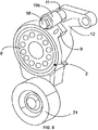
- the present invention consists in replacing the conventional stop of a tensioning roller 2 by a stop 10b, 10c having an abutment element 17, 19 which can absorb the kinetic energy of the tensioner roller 2 in the transforming into elastic deformation energy. The risk of breakage of the abutment 10b, 10c is then discarded.
- the present invention relates to a tensioning roller 2 for transmission belt 4, which comprises a support portion 12 intended to be fixed at at least one attachment point 11 by a fastening element 18 to a set 1 carrying at least two pulleys. 3, 5, 7 surrounded by the transmission belt 4.
- This assembly 1 is advantageously an accessory front of a motor vehicle casing of a motor vehicle but this is not limiting.
- the tensioning roller 2 comprises a tension roller 21 carried by a pivoting arm 8, the pivoting arm 8 having a cocking finger 9 which can come into abutment with an end stop 10a, 10b, 10c carried by the support portion 12.
- Stopper 10a shown in figure 2 conforms to the state of the art, while the abutments 10b and 10c shown in figures 3 , 4 or respectively 5, 6, 7a, 7b, 7c are according to the present invention.
- the abutment stop 10b, 10c is independent of the tensioner roller 2 and is fixed on the support portion 12 of the tensioner roller 2 to said at least one attachment point 11 by said fastening element 18 of the part support, this abutment 10b, 10c end of stroke having an abutment member 17, 19 for the cocking finger 9, this abutment member 17, 19 being elastically deformable.
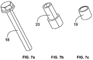
- the conventional stop 10a of a tensioning roller 2 incorporated in the aluminum foundry of the tensioning roller is replaced in a first embodiment shown in FIGS. figures 3 and 4 by a stop 10b having a steel part forming a deformable wing 17 and in a second mode shown in FIGS. figures 5 , 6 , 7a, 7b, 7c by an elastomeric sleeve 19 fixed on the same point of attachment 11 as the support portion 12 of the tensioner roller 2.
- the abutment 10b, 10c may have a bore superimposed on a bore of the support portion 12.
- the fastening element 18 is a threaded rod passing through the abutment 10b, 10c and the support portion 12 and is intended to be screwed to the assembly 1.
- the abutment 10b comprises a base 22 resting on the support portion 12 in the fixed position of the abutment 10b and a wing 17 made of steel as an abutment element.
- the wing 17 extends substantially perpendicular to the base 22 of the abutment 10b.
- This wing 17 ensures when it is in contact with the cocking finger 9 a leaf spring function, the thickness of the wing 17 being predetermined so that the wing 17 deforms when the pressure of the cocking finger 9 on the wing 17 exceeds a fixed threshold.
- the wing 17 is sufficiently flexible and resistant to absorb the kinetic energy in rotation of the tensioner roller when that comes to abut the cocking finger 9.
- the threshold set has been defined as that from which the impact between the cocking finger 9 and the abutment 10b is likely to damage the stop. These shocks may correspond to situations such as starting the engine, operating under engine speed or a violent clutch release.
- the wing 17 can be obtained by folding a sheet forming the abutment 10b, at least to form the wing 17.
- the base 22 of the abutment 10b can be fixed with respect to the support portion 12 in two fixing points illustrated by the bores 11, these two attachment points 11 being respectively merged with the points intended for fixing the part of support 12 of the tensioner roller on the assembly. It is for each fixing point the same fastening element 18 which serves for fixing the abutment 10b on the support portion 12 of the tensioner roller and for fixing the support portion 12 of the tensioner roller on the assembly.
- the base 22 of the abutment 10b is fixed relative to the support portion 12 of the tensioner roller 2 in a single attachment point 11.
- an anti-rotation positioning tab 16 is provided on the base 22 of the 10b stop, this anti-rotation positioning tab 16 preventing the abutment 10b to pivot around the single point of attachment 11.
- a fold of sheet metal can serve as anti-rotation tongue 16 which can also be used for indexing for the mounting.
- the other sheet bend provides the wing function 17 as a leaf spring, as previously indicated.
- the positioning tongue 16 can make an obtuse angle with the abutment base 22b extending in the opposite direction of the flange 17 and being mounted on the abutment 10b in a position substantially opposite to the flange 17.
- the abutment element 17, 19 is in the form of an elastomeric sleeve 19.
- This elastomeric sleeve 19 is dimensioned so as to absorb the kinetic energy of the tensioner roller in terms of energy. elastic deformation with viscous dissipation in the elastomer. The risk of breakage of the abutment 10c is then discarded.
- the elastomeric sleeve 19 is carried by the upper part of the fastening element 18 fixing the support portion 12 on the assembly.
- a metal spacer 20 may be provided with a portion of this spacer 20 that can be interposed between at least a portion of the sleeve 19 and a portion of the fastener 18 surrounded by the sleeve 19.
- the elastomeric sleeve 19 advantageously surrounds the entire part upper part of the fixing element 18 with or without interposed spacer 20.
- the fastening element 18 is advantageously in the form of a longer screw than the other fixing elements of the tensioning roller in order to be able to bear the elastomeric sleeve 19.
- the spacer 20 is advantageously metallic, made of steel or aluminum, and can carry a flange at its end facing the screwing end of the fastening element 18. This flange, outside the elastomeric sleeve 19 can then abut on the lower part of the elastomeric sleeve 19.
- the spacer 20 and the elastomeric sleeve 19 can therefore be inserted between the head of the fastening element 18 while being traversed by the remainder of this fastening element 18 which also passes through the support portion 12 of the tensioner roller. It is the metal spacer 20 which takes up only the clamping force.
- the elastomer sleeve 19 can be mounted slightly tightly around the spacer 20, advantageously around a portion of the spacer 20.
- Such stops 10b, 10c according to the two non-limiting modes mentioned above have the advantage of being easily mounted on tensioning rollers existing and do not pose any particular problem of assembly. Only longer fastening elements 18 are to be provided for fastening the support portion 12 of the tensioner roller to the assembly, since the fastening elements serving only for fastening the support portion as in the state of the technique.
- the invention relates to a transmission belt drive system 4 comprising at least two pulleys 3, 5, 7 surrounded by a transmission belt 4, at least one of the pulleys 3, 5 , 7 driving the one or more pulleys 3, 5, 7.
- the drive system comprises at least one tensioner roller 2 which is associated with such a stop 10b or 10c as described in the two embodiments and in the variant previously mentioned as an alternative to the first mode.
- the invention also relates to an assembly 1 carrying at least two pulleys 3, 5, 7 surrounded by a transmission belt 4, each pulley 3, 5, 7 corresponding to an accessory 6 driving or driven assembly 1.
- This belt 4 transmission is part of a drive system as described above.
- the assembly is advantageously an accessory facade of a motor vehicle engine casing.
Landscapes
- Engineering & Computer Science (AREA)
- General Engineering & Computer Science (AREA)
- Mechanical Engineering (AREA)
- Devices For Conveying Motion By Means Of Endless Flexible Members (AREA)
Claims (10)
- Spannrolle (2) für Übertragungsriemen (4), die einen Tragteil (12) umfasst, der dazu bestimmt ist, in mindestens einem Befestigungspunkt (11) durch ein Befestigungselement (18) auf einer Baugruppe (1) befestigt zu werden, die mindestens zwei Scheiben (3, 5, 7) trägt, die von dem Übertragungsriemen (4) umgeben sind, wobei die Spannrolle (2) eine Rolle (21) umfasst, die von einem Schwenkarm (8) getragen wird, wobei der Schwenkarm (8) einen Rückstellfinger (9) aufweist, der mit einem Hubbegrenzungsanschlag (10b, 10c) zum Anschlagen kommen kann, der von dem Tragteil (12) getragen wird, dadurch gekennzeichnet, dass der Hubbegrenzungsanschlag (10b, 10c) von der Spannrolle (2) unabhängig und auf dem Tragteil (12) der Spannrolle (2) an dem mindestens einen Befestigungspunkt (11) durch das Befestigungselement (18) des Tragteils (12) befestigt ist, wobei der Hubbegrenzungsanschlag (10b, 10c) ein Anschlagelement (17, 19) für den Rückstellfinger (9) aufweist, wobei dieses Anschlagelement (17, 19) elastisch verformbar ist.
- Spannrolle (2) nach Anspruch 1, wobei der Anschlag (10b, 10c) an dem mindestens einen Befestigungspunkt (11) eine Bohrung aufweist, die einer Bohrung (11) des Tragteils (12) überlagert ist, wobei das Befestigungselement (18) ein Gewindestift ist, der nacheinander den Anschlag (10b, 10c) und den Tragteil (12) durchquert und dazu bestimmt ist, an die Baugruppe (1) geschraubt zu sein.
- Spannrolle (2) nach Anspruch 1 oder 2, wobei der Anschlag (10b) einen Sockel (22) umfasst, der auf dem Tragteil (12) in befestigter Position des Anschlags (10b) ruht, und einen Flügel (17) aus Stahl als Anschlagelement (17, 19), der sich im Wesentlichen senkrecht zu dem Sockel (22) des Anschlags (10b) erstreckt, wobei der Flügel (17) bei seiner Berührung mit dem Rückstellfinger (9) eine Blattfederfunktion sicherstellt, wobei die Stärke des Flügels (17) derart vorausbestimmt ist, dass sich der Flügel (17) verformt, wenn der Druck des Rückstellfingers (9) auf dem Flügel (17) einen festgelegten Schwellenwert überschreitet.
- Spannrolle (2) nach Anspruch 3, wobei der Sockel (22) des Anschlags (10b) in Bezug auf den Tragteil (12) in zwei Befestigungspunkten (11) befestigt ist, wobei diese zwei Befestigungspunkte (11) jeweils mit den Punkten übereinstimmen, die zum Befestigen des Tragteils (12) auf der Baugruppe (1) bestimmt sind.
- Spannrolle (2) nach Anspruch 3, wobei der Sockel (22) des Anschlags (10b) in Bezug auf den Tragteil (12) an einem Befestigungspunkt (11) befestigt ist, wobei eine Drehschutz-Positionierungslasche (16) auf dem Sockel (22) des Anschlags (10b, 10c) vorgesehen ist.
- Spannrolle (2) nach Anspruch 5, wobei die Positionierungslasche (16) einen stumpfen Winkel mit dem Sockel (22) des Anschlags (10b) bildet, indem sie sich in die umgekehrte Richtung zu der des Flügels (17) erstreckt.
- Spannrolle (2) nach Anspruch 1 oder 2, wobei das Anschlagelement (17, 19) die Form einer Elastomermuffe (19) hat.
- Spannrolle (2) nach Anspruch 7, wobei die Elastomermuffe (19) von und um den oberen Teil des Befestigungselements (18), das den Tragteil (12) auf der Baugruppe (1) befestigt, getragen wird, wobei ein metallischer Abstandhalter (20) zwischen die Muffe (19) und das Befestigungselement (18) eingefügt ist.
- Antriebssystem mit Übertragungsriemen (4), das mindestens zwei Scheiben (3, 5, 7) umfasst, die von einem Übertragungsriemen (4) umgeben sind, wobei mindestens eine der Scheiben (3, 5, 7) die andere(n) Scheibe(n) (3, 5, 7) antreibt, dadurch gekennzeichnet, dass es mindestens eine Spannrolle (2) nach einem der vorhergehenden Ansprüche umfasst.
- Baugruppe (1), die mindestens zwei Scheiben (3, 5, 7) trägt, die von einem Übertragungsriemen (4) umgeben sind, wobei jede der Scheiben (3, 5, 7) einem antreibenden oder angetriebenen Zubehörteil (6) der Baugruppe (1) entspricht, dadurch gekennzeichnet, dass der Übertragungsriemen (4) zu dem Antriebssystem nach Anspruch 9 gehört.
Applications Claiming Priority (1)
| Application Number | Priority Date | Filing Date | Title |
|---|---|---|---|
| FR1359879A FR3011899B1 (fr) | 2013-10-11 | 2013-10-11 | Butee pour galet tendeur d'une courroie |
Publications (2)
| Publication Number | Publication Date |
|---|---|
| EP2860424A1 EP2860424A1 (de) | 2015-04-15 |
| EP2860424B1 true EP2860424B1 (de) | 2016-04-20 |
Family
ID=49713312
Family Applications (1)
| Application Number | Title | Priority Date | Filing Date |
|---|---|---|---|
| EP14185794.6A Active EP2860424B1 (de) | 2013-10-11 | 2014-09-22 | Anschlag für Spannrolle eines Riemens |
Country Status (2)
| Country | Link |
|---|---|
| EP (1) | EP2860424B1 (de) |
| FR (1) | FR3011899B1 (de) |
Families Citing this family (4)
| Publication number | Priority date | Publication date | Assignee | Title |
|---|---|---|---|---|
| FR3041403B1 (fr) * | 2015-09-17 | 2017-10-06 | Peugeot Citroen Automobiles Sa | Tendeur de courroie a montage et demontage sur un ensemble dans un environnement confine |
| FR3066245B1 (fr) * | 2017-05-10 | 2019-06-07 | Peugeot Citroen Automobiles Sa | Ensemble comprenant un support et un guide chaine ou courroie avec des moyens de positionnement du guide |
| FR3109976B1 (fr) | 2020-05-07 | 2023-07-14 | Valeo Embrayages | Système de transmission de puissance pour une chaîne de traction d’un véhicule automobile |
| FR3115851B1 (fr) | 2020-11-05 | 2023-07-14 | Valeo Embrayages | Dispositif de transmission à courroie(s). |
Family Cites Families (4)
| Publication number | Priority date | Publication date | Assignee | Title |
|---|---|---|---|---|
| JP4073492B2 (ja) | 1996-08-21 | 2008-04-09 | テスマ インターナショナル インコーポレイテツド | モータビークルのベルトテンショナー |
| US7163478B2 (en) * | 2001-12-12 | 2007-01-16 | Dayco Products, Llc | Belt tensioner having an automatically adjustable travel stop |
| DE102009056610A1 (de) * | 2009-12-02 | 2011-06-09 | Schaeffler Technologies Gmbh & Co. Kg | Spannsystem mit zwei getrennten, um eine Drehachse schwenkbaren Spannvorrichtungen |
| FR2986595B1 (fr) * | 2012-02-02 | 2014-05-23 | Peugeot Citroen Automobiles Sa | Procede de controle d'un groupe motopropulseur pour la protection d'un tendeur de courroie d'accessoires |
-
2013
- 2013-10-11 FR FR1359879A patent/FR3011899B1/fr not_active Expired - Fee Related
-
2014
- 2014-09-22 EP EP14185794.6A patent/EP2860424B1/de active Active
Also Published As
| Publication number | Publication date |
|---|---|
| EP2860424A1 (de) | 2015-04-15 |
| FR3011899B1 (fr) | 2016-04-01 |
| FR3011899A1 (fr) | 2015-04-17 |
Similar Documents
| Publication | Publication Date | Title |
|---|---|---|
| EP0742377B1 (de) | Elastische Kupplungsvorrichtung für Kraftfahrzeuge, insbesondere Riemscheibe mit einer elastischen Kupplung | |
| EP2860424B1 (de) | Anschlag für Spannrolle eines Riemens | |
| WO2007034060A1 (fr) | Poulie de transmission de puissance | |
| FR2717546A1 (fr) | Tendeur de courroie. | |
| FR2977641A1 (fr) | Systeme de demarreur electrique entraine par courroie | |
| FR2836186A1 (fr) | Ventilateur a flux axial | |
| FR2781025A1 (fr) | Embrayage pour vehicule automobile | |
| EP0926396B1 (de) | Spannvorrichtung, Motor mit einer derartigen Vorrichtung und Verfahren zum Einbau einer solchen Vorrichtung | |
| WO2011154865A1 (fr) | Poulie decoupleuse a ressort spirale | |
| FR2875882A1 (fr) | Siege a pivot deporte et amortisseur de torsion l'incluant | |
| FR2727730A1 (fr) | Embrayage a friction a disque d'embrayage comportant un amortisseur de torsion | |
| FR2823275A1 (fr) | Dispositif pour actionner une piece avec amortisseur elastique et procede de fabrication du dispositif | |
| EP3350479B1 (de) | Riemenspanner zum anlegen an und entfernen von einer baugruppe in einem geschlossenen raum | |
| EP0670436B1 (de) | Riemenspanner für einen Verbrennungsmotor eines Kraftfahrzeugs | |
| EP0578556A1 (de) | Riemenspanner für eine Brennkraftmaschine | |
| EP1977143A1 (de) | Kurbelwellenscheibe | |
| FR2669980A1 (fr) | Butee de debrayage a rondelle elastique externe, notamment pour vehicules automobiles. | |
| FR2665498A1 (fr) | Dispositif d'immobilisation d'un galet tendeur de courroie, chaine ou analogue, sur une surface d'appui appartenant par exemple a un carter de moteur de vehicule. | |
| FR2943111A1 (fr) | Tendeur de courroie | |
| FR2848953A1 (fr) | Dispositif d'essuie-glace, notamment pour vehicule automobile | |
| FR3001266A1 (fr) | Systeme d'accouplement mecanique | |
| FR3091915A1 (fr) | « Pièce métallique pour un moteur à combustion interne et ensemble comportant une telle pièce » | |
| FR2990487A1 (fr) | Tendeur pour courroie d'accessoires d'un moteur thermique | |
| FR3076334B1 (fr) | Ensemble poulie a embrayage a limitation de choc ameliore | |
| EP4012223A1 (de) | Thermostat-riemenspanner für kaltstart |
Legal Events
| Date | Code | Title | Description |
|---|---|---|---|
| PUAI | Public reference made under article 153(3) epc to a published international application that has entered the european phase |
Free format text: ORIGINAL CODE: 0009012 |
|
| 17P | Request for examination filed |
Effective date: 20140922 |
|
| AK | Designated contracting states |
Kind code of ref document: A1 Designated state(s): AL AT BE BG CH CY CZ DE DK EE ES FI FR GB GR HR HU IE IS IT LI LT LU LV MC MK MT NL NO PL PT RO RS SE SI SK SM TR |
|
| AX | Request for extension of the european patent |
Extension state: BA ME |
|
| R17P | Request for examination filed (corrected) |
Effective date: 20151002 |
|
| RBV | Designated contracting states (corrected) |
Designated state(s): AL AT BE BG CH CY CZ DE DK EE ES FI FR GB GR HR HU IE IS IT LI LT LU LV MC MK MT NL NO PL PT RO RS SE SI SK SM TR |
|
| GRAP | Despatch of communication of intention to grant a patent |
Free format text: ORIGINAL CODE: EPIDOSNIGR1 |
|
| RIC1 | Information provided on ipc code assigned before grant |
Ipc: F16H 7/12 20060101AFI20151106BHEP |
|
| INTG | Intention to grant announced |
Effective date: 20151217 |
|
| GRAS | Grant fee paid |
Free format text: ORIGINAL CODE: EPIDOSNIGR3 |
|
| GRAA | (expected) grant |
Free format text: ORIGINAL CODE: 0009210 |
|
| AK | Designated contracting states |
Kind code of ref document: B1 Designated state(s): AL AT BE BG CH CY CZ DE DK EE ES FI FR GB GR HR HU IE IS IT LI LT LU LV MC MK MT NL NO PL PT RO RS SE SI SK SM TR |
|
| REG | Reference to a national code |
Ref country code: GB Ref legal event code: FG4D Free format text: NOT ENGLISH |
|
| REG | Reference to a national code |
Ref country code: CH Ref legal event code: EP |
|
| REG | Reference to a national code |
Ref country code: AT Ref legal event code: REF Ref document number: 792811 Country of ref document: AT Kind code of ref document: T Effective date: 20160515 |
|
| REG | Reference to a national code |
Ref country code: IE Ref legal event code: FG4D Free format text: LANGUAGE OF EP DOCUMENT: FRENCH |
|
| REG | Reference to a national code |
Ref country code: DE Ref legal event code: R096 Ref document number: 602014001574 Country of ref document: DE |
|
| REG | Reference to a national code |
Ref country code: FR Ref legal event code: PLFP Year of fee payment: 3 |
|
| REG | Reference to a national code |
Ref country code: LT Ref legal event code: MG4D |
|
| REG | Reference to a national code |
Ref country code: AT Ref legal event code: MK05 Ref document number: 792811 Country of ref document: AT Kind code of ref document: T Effective date: 20160420 |
|
| REG | Reference to a national code |
Ref country code: NL Ref legal event code: MP Effective date: 20160420 |
|
| REG | Reference to a national code |
Ref country code: DE Ref legal event code: R084 Ref document number: 602014001574 Country of ref document: DE |
|
| PG25 | Lapsed in a contracting state [announced via postgrant information from national office to epo] |
Ref country code: FI Free format text: LAPSE BECAUSE OF FAILURE TO SUBMIT A TRANSLATION OF THE DESCRIPTION OR TO PAY THE FEE WITHIN THE PRESCRIBED TIME-LIMIT Effective date: 20160420 Ref country code: PL Free format text: LAPSE BECAUSE OF FAILURE TO SUBMIT A TRANSLATION OF THE DESCRIPTION OR TO PAY THE FEE WITHIN THE PRESCRIBED TIME-LIMIT Effective date: 20160420 Ref country code: LT Free format text: LAPSE BECAUSE OF FAILURE TO SUBMIT A TRANSLATION OF THE DESCRIPTION OR TO PAY THE FEE WITHIN THE PRESCRIBED TIME-LIMIT Effective date: 20160420 Ref country code: NL Free format text: LAPSE BECAUSE OF FAILURE TO SUBMIT A TRANSLATION OF THE DESCRIPTION OR TO PAY THE FEE WITHIN THE PRESCRIBED TIME-LIMIT Effective date: 20160420 Ref country code: NO Free format text: LAPSE BECAUSE OF FAILURE TO SUBMIT A TRANSLATION OF THE DESCRIPTION OR TO PAY THE FEE WITHIN THE PRESCRIBED TIME-LIMIT Effective date: 20160720 |
|
| REG | Reference to a national code |
Ref country code: GB Ref legal event code: 746 Effective date: 20161011 |
|
| PG25 | Lapsed in a contracting state [announced via postgrant information from national office to epo] |
Ref country code: LV Free format text: LAPSE BECAUSE OF FAILURE TO SUBMIT A TRANSLATION OF THE DESCRIPTION OR TO PAY THE FEE WITHIN THE PRESCRIBED TIME-LIMIT Effective date: 20160420 Ref country code: HR Free format text: LAPSE BECAUSE OF FAILURE TO SUBMIT A TRANSLATION OF THE DESCRIPTION OR TO PAY THE FEE WITHIN THE PRESCRIBED TIME-LIMIT Effective date: 20160420 Ref country code: PT Free format text: LAPSE BECAUSE OF FAILURE TO SUBMIT A TRANSLATION OF THE DESCRIPTION OR TO PAY THE FEE WITHIN THE PRESCRIBED TIME-LIMIT Effective date: 20160822 Ref country code: SE Free format text: LAPSE BECAUSE OF FAILURE TO SUBMIT A TRANSLATION OF THE DESCRIPTION OR TO PAY THE FEE WITHIN THE PRESCRIBED TIME-LIMIT Effective date: 20160420 Ref country code: AT Free format text: LAPSE BECAUSE OF FAILURE TO SUBMIT A TRANSLATION OF THE DESCRIPTION OR TO PAY THE FEE WITHIN THE PRESCRIBED TIME-LIMIT Effective date: 20160420 Ref country code: GR Free format text: LAPSE BECAUSE OF FAILURE TO SUBMIT A TRANSLATION OF THE DESCRIPTION OR TO PAY THE FEE WITHIN THE PRESCRIBED TIME-LIMIT Effective date: 20160721 Ref country code: ES Free format text: LAPSE BECAUSE OF FAILURE TO SUBMIT A TRANSLATION OF THE DESCRIPTION OR TO PAY THE FEE WITHIN THE PRESCRIBED TIME-LIMIT Effective date: 20160420 Ref country code: RS Free format text: LAPSE BECAUSE OF FAILURE TO SUBMIT A TRANSLATION OF THE DESCRIPTION OR TO PAY THE FEE WITHIN THE PRESCRIBED TIME-LIMIT Effective date: 20160420 |
|
| PG25 | Lapsed in a contracting state [announced via postgrant information from national office to epo] |
Ref country code: IT Free format text: LAPSE BECAUSE OF FAILURE TO SUBMIT A TRANSLATION OF THE DESCRIPTION OR TO PAY THE FEE WITHIN THE PRESCRIBED TIME-LIMIT Effective date: 20160420 |
|
| REG | Reference to a national code |
Ref country code: DE Ref legal event code: R097 Ref document number: 602014001574 Country of ref document: DE |
|
| PG25 | Lapsed in a contracting state [announced via postgrant information from national office to epo] |
Ref country code: EE Free format text: LAPSE BECAUSE OF FAILURE TO SUBMIT A TRANSLATION OF THE DESCRIPTION OR TO PAY THE FEE WITHIN THE PRESCRIBED TIME-LIMIT Effective date: 20160420 Ref country code: RO Free format text: LAPSE BECAUSE OF FAILURE TO SUBMIT A TRANSLATION OF THE DESCRIPTION OR TO PAY THE FEE WITHIN THE PRESCRIBED TIME-LIMIT Effective date: 20160420 Ref country code: DK Free format text: LAPSE BECAUSE OF FAILURE TO SUBMIT A TRANSLATION OF THE DESCRIPTION OR TO PAY THE FEE WITHIN THE PRESCRIBED TIME-LIMIT Effective date: 20160420 Ref country code: CZ Free format text: LAPSE BECAUSE OF FAILURE TO SUBMIT A TRANSLATION OF THE DESCRIPTION OR TO PAY THE FEE WITHIN THE PRESCRIBED TIME-LIMIT Effective date: 20160420 Ref country code: SK Free format text: LAPSE BECAUSE OF FAILURE TO SUBMIT A TRANSLATION OF THE DESCRIPTION OR TO PAY THE FEE WITHIN THE PRESCRIBED TIME-LIMIT Effective date: 20160420 |
|
| PLBE | No opposition filed within time limit |
Free format text: ORIGINAL CODE: 0009261 |
|
| STAA | Information on the status of an ep patent application or granted ep patent |
Free format text: STATUS: NO OPPOSITION FILED WITHIN TIME LIMIT |
|
| PG25 | Lapsed in a contracting state [announced via postgrant information from national office to epo] |
Ref country code: SM Free format text: LAPSE BECAUSE OF FAILURE TO SUBMIT A TRANSLATION OF THE DESCRIPTION OR TO PAY THE FEE WITHIN THE PRESCRIBED TIME-LIMIT Effective date: 20160420 Ref country code: BE Free format text: LAPSE BECAUSE OF NON-PAYMENT OF DUE FEES Effective date: 20160930 |
|
| 26N | No opposition filed |
Effective date: 20170123 |
|
| PG25 | Lapsed in a contracting state [announced via postgrant information from national office to epo] |
Ref country code: MC Free format text: LAPSE BECAUSE OF FAILURE TO SUBMIT A TRANSLATION OF THE DESCRIPTION OR TO PAY THE FEE WITHIN THE PRESCRIBED TIME-LIMIT Effective date: 20160420 |
|
| PG25 | Lapsed in a contracting state [announced via postgrant information from national office to epo] |
Ref country code: SI Free format text: LAPSE BECAUSE OF FAILURE TO SUBMIT A TRANSLATION OF THE DESCRIPTION OR TO PAY THE FEE WITHIN THE PRESCRIBED TIME-LIMIT Effective date: 20160420 |
|
| REG | Reference to a national code |
Ref country code: IE Ref legal event code: MM4A |
|
| PG25 | Lapsed in a contracting state [announced via postgrant information from national office to epo] |
Ref country code: IE Free format text: LAPSE BECAUSE OF NON-PAYMENT OF DUE FEES Effective date: 20160922 |
|
| REG | Reference to a national code |
Ref country code: FR Ref legal event code: PLFP Year of fee payment: 4 |
|
| PG25 | Lapsed in a contracting state [announced via postgrant information from national office to epo] |
Ref country code: LU Free format text: LAPSE BECAUSE OF NON-PAYMENT OF DUE FEES Effective date: 20160922 |
|
| REG | Reference to a national code |
Ref country code: BE Ref legal event code: MM Effective date: 20160930 |
|
| REG | Reference to a national code |
Ref country code: CH Ref legal event code: PL |
|
| PG25 | Lapsed in a contracting state [announced via postgrant information from national office to epo] |
Ref country code: HU Free format text: LAPSE BECAUSE OF FAILURE TO SUBMIT A TRANSLATION OF THE DESCRIPTION OR TO PAY THE FEE WITHIN THE PRESCRIBED TIME-LIMIT; INVALID AB INITIO Effective date: 20140922 |
|
| PG25 | Lapsed in a contracting state [announced via postgrant information from national office to epo] |
Ref country code: CY Free format text: LAPSE BECAUSE OF FAILURE TO SUBMIT A TRANSLATION OF THE DESCRIPTION OR TO PAY THE FEE WITHIN THE PRESCRIBED TIME-LIMIT Effective date: 20160420 Ref country code: MK Free format text: LAPSE BECAUSE OF FAILURE TO SUBMIT A TRANSLATION OF THE DESCRIPTION OR TO PAY THE FEE WITHIN THE PRESCRIBED TIME-LIMIT Effective date: 20160420 Ref country code: IS Free format text: LAPSE BECAUSE OF FAILURE TO SUBMIT A TRANSLATION OF THE DESCRIPTION OR TO PAY THE FEE WITHIN THE PRESCRIBED TIME-LIMIT Effective date: 20160420 Ref country code: MT Free format text: LAPSE BECAUSE OF FAILURE TO SUBMIT A TRANSLATION OF THE DESCRIPTION OR TO PAY THE FEE WITHIN THE PRESCRIBED TIME-LIMIT Effective date: 20160420 |
|
| REG | Reference to a national code |
Ref country code: FR Ref legal event code: CA Effective date: 20180312 Ref country code: FR Ref legal event code: CD Owner name: PEUGEOT CITROEN AUTOMOBILES SA, FR Effective date: 20180312 |
|
| PG25 | Lapsed in a contracting state [announced via postgrant information from national office to epo] |
Ref country code: LI Free format text: LAPSE BECAUSE OF NON-PAYMENT OF DUE FEES Effective date: 20170930 Ref country code: CH Free format text: LAPSE BECAUSE OF NON-PAYMENT OF DUE FEES Effective date: 20170930 Ref country code: BG Free format text: LAPSE BECAUSE OF FAILURE TO SUBMIT A TRANSLATION OF THE DESCRIPTION OR TO PAY THE FEE WITHIN THE PRESCRIBED TIME-LIMIT Effective date: 20160420 |
|
| REG | Reference to a national code |
Ref country code: FR Ref legal event code: PLFP Year of fee payment: 5 |
|
| PG25 | Lapsed in a contracting state [announced via postgrant information from national office to epo] |
Ref country code: TR Free format text: LAPSE BECAUSE OF FAILURE TO SUBMIT A TRANSLATION OF THE DESCRIPTION OR TO PAY THE FEE WITHIN THE PRESCRIBED TIME-LIMIT Effective date: 20160420 Ref country code: AL Free format text: LAPSE BECAUSE OF FAILURE TO SUBMIT A TRANSLATION OF THE DESCRIPTION OR TO PAY THE FEE WITHIN THE PRESCRIBED TIME-LIMIT Effective date: 20160420 |
|
| PGFP | Annual fee paid to national office [announced via postgrant information from national office to epo] |
Ref country code: GB Payment date: 20240820 Year of fee payment: 11 |
|
| PGFP | Annual fee paid to national office [announced via postgrant information from national office to epo] |
Ref country code: DE Payment date: 20250820 Year of fee payment: 12 |
|
| PGFP | Annual fee paid to national office [announced via postgrant information from national office to epo] |
Ref country code: FR Payment date: 20250820 Year of fee payment: 12 |