EP2863501A2 - Élément de liaison, partie de caisson et kit destiné à former un caisson à insérer dans une niche - Google Patents
Élément de liaison, partie de caisson et kit destiné à former un caisson à insérer dans une niche Download PDFInfo
- Publication number
- EP2863501A2 EP2863501A2 EP20140181358 EP14181358A EP2863501A2 EP 2863501 A2 EP2863501 A2 EP 2863501A2 EP 20140181358 EP20140181358 EP 20140181358 EP 14181358 A EP14181358 A EP 14181358A EP 2863501 A2 EP2863501 A2 EP 2863501A2
- Authority
- EP
- European Patent Office
- Prior art keywords
- box
- connecting element
- parts
- box parts
- open
- Prior art date
- Legal status (The legal status is an assumption and is not a legal conclusion. Google has not performed a legal analysis and makes no representation as to the accuracy of the status listed.)
- Granted
Links
Images


Classifications
-
- H—ELECTRICITY
- H02—GENERATION; CONVERSION OR DISTRIBUTION OF ELECTRIC POWER
- H02G—INSTALLATION OF ELECTRIC CABLES OR LINES, OR OF COMBINED OPTICAL AND ELECTRIC CABLES OR LINES
- H02G3/00—Installations of electric cables or lines or protective tubing therefor in or on buildings, equivalent structures or vehicles
- H02G3/02—Details
- H02G3/08—Distribution boxes; Connection or junction boxes
- H02G3/12—Distribution boxes; Connection or junction boxes for flush mounting
-
- H—ELECTRICITY
- H02—GENERATION; CONVERSION OR DISTRIBUTION OF ELECTRIC POWER
- H02B—BOARDS, SUBSTATIONS OR SWITCHING ARRANGEMENTS FOR THE SUPPLY OR DISTRIBUTION OF ELECTRIC POWER
- H02B1/00—Frameworks, boards, panels, desks, casings; Details of substations or switching arrangements
- H02B1/01—Frameworks
- H02B1/012—Details of mechanical connections
-
- H—ELECTRICITY
- H02—GENERATION; CONVERSION OR DISTRIBUTION OF ELECTRIC POWER
- H02B—BOARDS, SUBSTATIONS OR SWITCHING ARRANGEMENTS FOR THE SUPPLY OR DISTRIBUTION OF ELECTRIC POWER
- H02B1/00—Frameworks, boards, panels, desks, casings; Details of substations or switching arrangements
- H02B1/26—Casings; Parts thereof or accessories therefor
- H02B1/40—Wall-mounted casings; Parts thereof or accessories therefor
Definitions
- the invention relates to a connecting element, a box part and a kit for forming a box to be installed in a wall niche for receiving devices for distributing electrical energy in buildings and / or other components of the electrical installation.
- one of the distribution boxes is selected which is suitable for receiving the respective devices to be installed.
- the invention has for its object to provide a box of the type mentioned, which can be easily adapted to requirements that are made by the electrical installation.
- the task-solving connecting element is characterized in that it is adapted to connect to the formation of the box provided box parts that are open on at least one side at the open sides together.
- the box part according to the invention solves the problem in that it is open on at least one side and on the open side for receiving a connecting element, by means of which the box part to form the box with another box part is connectable.
- the task-solving kit according to the invention comprises at least two of the aforementioned box parts, optionally a cover provided therefor, e.g. a frame, a door, a flap or the like, and for connecting the box parts, the aforementioned connecting element.
- the box can be assembled from the box parts and the connecting element in size and functionality to suit requirements imposed by the electrical installation.
- different box parts may be provided, which may have different sizes and / or are differently equipped.
- the box may in the preferred embodiment of the invention by the box parts both for accommodating conventional devices of electrical installation such as circuit breakers, RCCBs and the like also for accommodating telecommunications devices, such as a broadband connection switch, a modem, a router, a telephone system or the like to get prepared.
- the box consists of more than two box parts and more than one connecting element, wherein at least one, preferably to be arranged between two other box parts, inner box part is open on opposite sides and set up on these sides for connection via the connecting element.
- the box can be constructed as required from any number of box parts and it is possible to retrofit an already installed box according to the invention subsequently with a box part or more box parts.
- the connecting element is provided to rigidly connect the box parts together so that it can transmit bending moments between the box parts.
- the box parts are expediently connectable to one another by the connecting element such that the box to be formed in its entirety has a similarly great resistance to elastic deformation as a comparable one-piece box.
- it can then handle as the one-piece box.
- the connecting element and the box part are plugged into each other.
- the connecting element expediently has a plug-in element which is provided for use in a plug-receiving device formed in the box part. It may comprise a link that for engaging over an edge of a side wall of the box part, preferably for arrangement while assuming a stable seating position on the side wall, is set up.
- the connecting element can also be used in a guide groove formed on the box part, latched to the box part and / or for connection to the box part by means of a fastening part, preferably a screw, a rivet or the like, be configured, for example, by already formed on the connecting element, if necessary Threaded hole.
- a fastening part preferably a screw, a rivet or the like
- the connecting element separates the box parts from one another such that the box parts form compartments in the box interior.
- the individual compartments can be used to hold devices of a specific functional area.
- one of the compartments for receiving the said devices of the electrical installation and another of the compartments for receiving telecommunication devices can be set up.
- the connecting element expediently has an opening or a recess open on one side, through which or the cables can be guided.
- the opening and / or the recess can be closed by a blocking plate which can be inserted into grooves, if necessary, in order to be able to completely separate the compartments from one another.
- the connecting element is formed such that it keeps the box parts at a distance to each other.
- said cover preferably the said frame or the door, on each one of the box parts.
- the cover is preferably formed such that it can be placed on an upper edge of the side walls of the respective box part and possibly on an upper side of the connecting element, wherein it preferably surrounds the side walls.
- the connecting element is in a further embodiment of the invention, at least partially closed to the outside, preferably box-like, Recording space formed, for example, as a storage space for small parts, plans or the like, which may be required in subsequent installation work, for receiving a cooling device for thermal regulation of the interior of the distribution box and / or for receiving a means for illuminating the box.
- Recording space formed, for example, as a storage space for small parts, plans or the like, which may be required in subsequent installation work, for receiving a cooling device for thermal regulation of the interior of the distribution box and / or for receiving a means for illuminating the box.
- the receiving space may also be provided for receiving a connection element, preferably at least one socket, a terminal block and / or a cable clamp. Conveniently, it is provided on its two sides facing the box parts, each with an opening, so that the connection element from both sides of the connecting element ago, i. from any box part, is contactable.
- the socket can be provided for connection of the devices to be arranged in the box or for supplying the devices with power.
- the connecting element is expediently provided in such a way that lines leading to or from the connecting element can be guided directly outward from the connecting element, preferably through the connecting element between the box parts to the outside of the formed box.
- the connecting element can then be used to supply lines in the box.
- the connecting element is provided with a holding device which is provided for the arrangement of a means for fixing in the box to be laid cable.
- the holding device preferably comprises a DIN rail, a pin or a groove of a dovetail joint, a receptacle for terminals and / or a bore for receiving screws or the like.
- the fastening means may be formed by cable ties or a cable clamp.
- the box can be fastened by means of the connecting part in the wall niche.
- the connecting part for attaching the box in the wall niche is provided with at least one, preferably swingable, anchor element with which the box can be clamped to the wall.
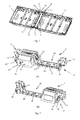
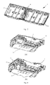
- Fig. 1 two box parts 2, 3 are shown, which by means of a in Fig. 2 shown connecting element 4 to a in Fig. 4 Assemble illustrated box 1.
- the box 1 is designed to form an electrical distributor and / or to accommodate other components of the electrical installation of buildings, such as telecommunication devices, and is intended to be mounted in a wall niche formed under plaster or formed on a cavity wall.
- each of the box parts 2, 3 on sides 5, 6, to which the box parts 2, 3 can be connected to each other, is open.
- On the sides 5,6 of the box parts 2,3 are each opposite the same shape having plug-in receptacles 9,10,11,12 formed for receiving the connecting element 4, which in more detail in Fig. 8 are shown.
- the connecting element 4 is provided with four plug-in elements 13,14,15,16, which are inserted in each one of the plug-in receptacles 9,10,11,12.
- Each of the plug-in elements 13,14,15,16 has a holding member 17 which is provided for engaging over an edge 35 of a side wall 36 of the box parts 2,3 formed only partially on the sides 5,6, and a male member 18, which for insertion into a recess 37 of the plug-in receptacles 9, 10, 11, 12 is provided (reference numerals 35 to 37 in FIG Fig. 8 only intended for box part 2).
- the plug-in elements 13,14,15,16 are each provided with a bore 38,39,40,41, through which for fastening the connecting element to the box parts 2.3 each a screw not shown here is feasible, in threaded holes 42 at the bottom the recesses 37 of the plug-in receptacles 9,10,11,12 are screwed.
- Fig. 3 It can be seen how the connecting element 4 is arranged to form the box 1 with the arrangement of the plug-in elements 13,14,15,16 in the plug-in receptacles 9,10,11,12 between the box parts 2.3.
- the box parts 2.3 are so rigidly connected together that the formed box 1 is stable in bending and can be handled like a comparable one-piece box.
- a laterally closed receiving space 23 is formed, which in each case has an opening 19 on its sides facing the box parts 2, 3. As Fig. 4b shows, can be inserted into the openings 19, possibly from both sides of the connecting element 4, sockets 25. Furthermore, the receiving space 23 can be used as a storage space for small parts or plans or for receiving lighting for the box interior or a cooling device for the box 1.
- the receiving space 23 can be guided by a channel 24 to be arranged on the sides of the box 1 ends of the connecting element 4 forth to the socket 25 lines.
- a recess 20 is further provided, can be passed through the cable through which a box part 2.3 to the other box part 2,3.
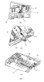
- means are provided for receiving fastening means for the cables, namely recesses 26,27 for insertion of a provided with a cable clamp 34 Traverse 33 (Fig. Fig. 6a ) or for direct use of a provided with appropriate fasteners terminal 30 ( Fig. 6b ).
- webs 28 are formed for receiving cable ties.
- locations 29 such webs are also formed on the back of the bottom of the recess 20. The latter webs serve to accommodate cable ties for cables that are to be arranged along the back of the box 1.
- two grooves 21 are formed parallel and spaced from each other, in which either a locking plate 22 can be used, with which the recess 20, as Fig. 5 shows, closes to separate the two box parts 2.3 from each other.
- Fig. 7 shows a further inventive connecting element 4a, which has at its two ends an armature 31, by means of which a of box parts 2a, 3a and the connection element 4a formed box on a wall on which the box is to install, can be clamped.
- Fig. 7b shows, on the upper side of the connecting element 4a, a lever 32 is formed, by means of which the armature 31 can be moved to an anchoring position.
- the box in particular due to the rigid design of the box parts 2a, 3a and the connecting element 4a, already arranged by applying the armature 31a on the side wall stable in the niche.
Landscapes
- Engineering & Computer Science (AREA)
- Power Engineering (AREA)
- Architecture (AREA)
- Civil Engineering (AREA)
- Structural Engineering (AREA)
- Casings For Electric Apparatus (AREA)
- Connection Or Junction Boxes (AREA)
- Cartons (AREA)
Applications Claiming Priority (2)
| Application Number | Priority Date | Filing Date | Title |
|---|---|---|---|
| DE201310221122 DE102013221122A1 (de) | 2013-10-17 | 2013-10-17 | Verbindungselement, Kastenteil und Bausatz zur Bildung eines in eine Wandnische einzubauenden Kastens |
| DE102013114754 | 2013-12-23 |
Publications (3)
| Publication Number | Publication Date |
|---|---|
| EP2863501A2 true EP2863501A2 (fr) | 2015-04-22 |
| EP2863501A3 EP2863501A3 (fr) | 2015-08-19 |
| EP2863501B1 EP2863501B1 (fr) | 2023-04-26 |
Family
ID=51421816
Family Applications (1)
| Application Number | Title | Priority Date | Filing Date |
|---|---|---|---|
| EP14181358.4A Active EP2863501B1 (fr) | 2013-10-17 | 2014-08-19 | Élément de liaison, partie de caisson et kit destiné à former un caisson à insérer dans une niche |
Country Status (3)
| Country | Link |
|---|---|
| EP (1) | EP2863501B1 (fr) |
| AU (3) | AU2014240199A1 (fr) |
| ES (1) | ES2949973T3 (fr) |
Cited By (1)
| Publication number | Priority date | Publication date | Assignee | Title |
|---|---|---|---|---|
| CN106712540A (zh) * | 2017-01-05 | 2017-05-24 | 四川埃姆克伺服科技有限公司 | 一种大功率器件结构 |
Family Cites Families (7)
| Publication number | Priority date | Publication date | Assignee | Title |
|---|---|---|---|---|
| FR2698516B1 (fr) * | 1992-11-25 | 1995-02-03 | Legrand Sa | Dispositif de jumelage pour embase, notamment pour coffret électrique. |
| DE4310071C2 (de) * | 1993-03-27 | 1996-03-21 | Abb Patent Gmbh | Isolierstoffgehäuseanordnung |
| DE29512560U1 (de) * | 1995-08-03 | 1995-10-12 | Ilme S.p.A., Mailand/Milano | Gehäuseanordnung für elektrische Elemente |
| IT1302113B1 (it) * | 1998-03-17 | 2000-07-26 | Bticino Spa | Elemento di connessione elettrica tra sbarre di distribuzione eapparecchi elettrici modulari |
| ITTO20060188A1 (it) * | 2006-03-10 | 2007-09-11 | Schneider Electric Ind Sas | Scatola per involucro di quadro elettrico |
| FR2950204B1 (fr) * | 2009-09-14 | 2011-11-04 | Legrand France | Boite pour appareillages electriques |
| FR2987943B1 (fr) * | 2012-03-12 | 2015-03-06 | Finatech Entpr S | Tableau electrique modulable |
-
2014
- 2014-08-19 ES ES14181358T patent/ES2949973T3/es active Active
- 2014-08-19 EP EP14181358.4A patent/EP2863501B1/fr active Active
- 2014-09-30 AU AU2014240199A patent/AU2014240199A1/en not_active Abandoned
-
2016
- 2016-06-24 AU AU2016102388A patent/AU2016102388A4/en not_active Expired
- 2016-06-24 AU AU2016204325A patent/AU2016204325A1/en active Pending
Non-Patent Citations (1)
| Title |
|---|
| None |
Cited By (2)
| Publication number | Priority date | Publication date | Assignee | Title |
|---|---|---|---|---|
| CN106712540A (zh) * | 2017-01-05 | 2017-05-24 | 四川埃姆克伺服科技有限公司 | 一种大功率器件结构 |
| CN106712540B (zh) * | 2017-01-05 | 2023-06-13 | 四川埃姆克伺服科技有限公司 | 一种大功率器件结构 |
Also Published As
| Publication number | Publication date |
|---|---|
| AU2016102388A4 (en) | 2019-05-02 |
| EP2863501B1 (fr) | 2023-04-26 |
| AU2016204325A2 (en) | 2018-07-05 |
| EP2863501A3 (fr) | 2015-08-19 |
| AU2014240199A1 (en) | 2015-05-07 |
| ES2949973T3 (es) | 2023-10-04 |
| AU2016204325A1 (en) | 2016-07-14 |
Similar Documents
| Publication | Publication Date | Title |
|---|---|---|
| DE2825673C2 (de) | Beweglicher Raumteiler mit elektrischen Installationselementen | |
| DE102008050700A1 (de) | Verteilerleiste und Geräteschrank | |
| EP0702441B1 (fr) | Appareillage d'installation électrique, notamment pour canalisations de câbles | |
| EP1431765A2 (fr) | Dispositif de couplage d'un compteur d'électricité à une plate-forme de support | |
| DE9203112U1 (de) | Montageelement für Installationskanäle | |
| DE102013221122A1 (de) | Verbindungselement, Kastenteil und Bausatz zur Bildung eines in eine Wandnische einzubauenden Kastens | |
| DE10359489A1 (de) | Elektrifiziereinrichtung für ein Rahmengestell eines Schaltschrankes oder Racks | |
| EP2863501B1 (fr) | Élément de liaison, partie de caisson et kit destiné à former un caisson à insérer dans une niche | |
| DE19511284C1 (de) | Geräteadapter für Stromsammelschienen eines Sammelschienensystems | |
| DE10005260C2 (de) | Isoliergehäuse für Verteilerklemme | |
| DE202008006111U1 (de) | Anschlussdose für ein Solarmodul | |
| DE2838371C2 (de) | Mehrfach-Schutzkontaktstromsteckschiene | |
| DE202014009976U1 (de) | Elektrische Abzweig-, Anschluß- und Verteilerdose | |
| DE10325938B4 (de) | Kleinverteiler | |
| DE102014114938B4 (de) | Zählerplatz mit einer Aufnahmevorrichtung für Zählerzusatzgeräte | |
| EP3419128A1 (fr) | Multiprise pour une boîte de distribution | |
| DE102004022785B4 (de) | Zählerschrank zur Aufnahme wenigstens eines Stromzählers | |
| DE102008061908B3 (de) | Steckdosenverteiler | |
| EP2793332B1 (fr) | Appareil d'installation électrique | |
| EP3217495A1 (fr) | Goulotte electrique | |
| EP4002618A1 (fr) | Couvercle pour une boîte d'installation | |
| DE202005008385U1 (de) | Elektrische Anschluß- und Verbindungsdose | |
| EP3217497B1 (fr) | Support d'appareil | |
| DE29720674U1 (de) | Anschlußkasten | |
| EP1463170A2 (fr) | Armoire de distribution ou pour compteur électrique |
Legal Events
| Date | Code | Title | Description |
|---|---|---|---|
| PUAI | Public reference made under article 153(3) epc to a published international application that has entered the european phase |
Free format text: ORIGINAL CODE: 0009012 |
|
| 17P | Request for examination filed |
Effective date: 20140819 |
|
| AK | Designated contracting states |
Kind code of ref document: A2 Designated state(s): AL AT BE BG CH CY CZ DE DK EE ES FI FR GB GR HR HU IE IS IT LI LT LU LV MC MK MT NL NO PL PT RO RS SE SI SK SM TR |
|
| AX | Request for extension of the european patent |
Extension state: BA ME |
|
| PUAL | Search report despatched |
Free format text: ORIGINAL CODE: 0009013 |
|
| AK | Designated contracting states |
Kind code of ref document: A3 Designated state(s): AL AT BE BG CH CY CZ DE DK EE ES FI FR GB GR HR HU IE IS IT LI LT LU LV MC MK MT NL NO PL PT RO RS SE SI SK SM TR |
|
| AX | Request for extension of the european patent |
Extension state: BA ME |
|
| RIC1 | Information provided on ipc code assigned before grant |
Ipc: H02G 3/12 20060101AFI20150716BHEP Ipc: H02B 1/40 20060101ALI20150716BHEP Ipc: H05K 5/02 20060101ALI20150716BHEP |
|
| R17P | Request for examination filed (corrected) |
Effective date: 20160219 |
|
| RBV | Designated contracting states (corrected) |
Designated state(s): AL AT BE BG CH CY CZ DE DK EE ES FI FR GB GR HR HU IE IS IT LI LT LU LV MC MK MT NL NO PL PT RO RS SE SI SK SM TR |
|
| 17Q | First examination report despatched |
Effective date: 20160531 |
|
| STAA | Information on the status of an ep patent application or granted ep patent |
Free format text: STATUS: EXAMINATION IS IN PROGRESS |
|
| GRAP | Despatch of communication of intention to grant a patent |
Free format text: ORIGINAL CODE: EPIDOSNIGR1 |
|
| STAA | Information on the status of an ep patent application or granted ep patent |
Free format text: STATUS: GRANT OF PATENT IS INTENDED |
|
| INTG | Intention to grant announced |
Effective date: 20230102 |
|
| GRAS | Grant fee paid |
Free format text: ORIGINAL CODE: EPIDOSNIGR3 |
|
| GRAA | (expected) grant |
Free format text: ORIGINAL CODE: 0009210 |
|
| STAA | Information on the status of an ep patent application or granted ep patent |
Free format text: STATUS: THE PATENT HAS BEEN GRANTED |
|
| AK | Designated contracting states |
Kind code of ref document: B1 Designated state(s): AL AT BE BG CH CY CZ DE DK EE ES FI FR GB GR HR HU IE IS IT LI LT LU LV MC MK MT NL NO PL PT RO RS SE SI SK SM TR |
|
| REG | Reference to a national code |
Ref country code: GB Ref legal event code: FG4D Free format text: NOT ENGLISH |
|
| REG | Reference to a national code |
Ref country code: CH Ref legal event code: EP |
|
| REG | Reference to a national code |
Ref country code: DE Ref legal event code: R096 Ref document number: 502014016541 Country of ref document: DE |
|
| REG | Reference to a national code |
Ref country code: AT Ref legal event code: REF Ref document number: 1563528 Country of ref document: AT Kind code of ref document: T Effective date: 20230515 |
|
| REG | Reference to a national code |
Ref country code: IE Ref legal event code: FG4D Free format text: LANGUAGE OF EP DOCUMENT: GERMAN |
|
| P01 | Opt-out of the competence of the unified patent court (upc) registered |
Effective date: 20230606 |
|
| REG | Reference to a national code |
Ref country code: LT Ref legal event code: MG9D |
|
| REG | Reference to a national code |
Ref country code: NL Ref legal event code: MP Effective date: 20230426 |
|
| PG25 | Lapsed in a contracting state [announced via postgrant information from national office to epo] |
Ref country code: NL Free format text: LAPSE BECAUSE OF FAILURE TO SUBMIT A TRANSLATION OF THE DESCRIPTION OR TO PAY THE FEE WITHIN THE PRESCRIBED TIME-LIMIT Effective date: 20230426 |
|
| REG | Reference to a national code |
Ref country code: ES Ref legal event code: FG2A Ref document number: 2949973 Country of ref document: ES Kind code of ref document: T3 Effective date: 20231004 |
|
| PG25 | Lapsed in a contracting state [announced via postgrant information from national office to epo] |
Ref country code: SE Free format text: LAPSE BECAUSE OF FAILURE TO SUBMIT A TRANSLATION OF THE DESCRIPTION OR TO PAY THE FEE WITHIN THE PRESCRIBED TIME-LIMIT Effective date: 20230426 Ref country code: PT Free format text: LAPSE BECAUSE OF FAILURE TO SUBMIT A TRANSLATION OF THE DESCRIPTION OR TO PAY THE FEE WITHIN THE PRESCRIBED TIME-LIMIT Effective date: 20230828 Ref country code: NO Free format text: LAPSE BECAUSE OF FAILURE TO SUBMIT A TRANSLATION OF THE DESCRIPTION OR TO PAY THE FEE WITHIN THE PRESCRIBED TIME-LIMIT Effective date: 20230726 |
|
| PG25 | Lapsed in a contracting state [announced via postgrant information from national office to epo] |
Ref country code: RS Free format text: LAPSE BECAUSE OF FAILURE TO SUBMIT A TRANSLATION OF THE DESCRIPTION OR TO PAY THE FEE WITHIN THE PRESCRIBED TIME-LIMIT Effective date: 20230426 Ref country code: PL Free format text: LAPSE BECAUSE OF FAILURE TO SUBMIT A TRANSLATION OF THE DESCRIPTION OR TO PAY THE FEE WITHIN THE PRESCRIBED TIME-LIMIT Effective date: 20230426 Ref country code: LV Free format text: LAPSE BECAUSE OF FAILURE TO SUBMIT A TRANSLATION OF THE DESCRIPTION OR TO PAY THE FEE WITHIN THE PRESCRIBED TIME-LIMIT Effective date: 20230426 Ref country code: LT Free format text: LAPSE BECAUSE OF FAILURE TO SUBMIT A TRANSLATION OF THE DESCRIPTION OR TO PAY THE FEE WITHIN THE PRESCRIBED TIME-LIMIT Effective date: 20230426 Ref country code: IS Free format text: LAPSE BECAUSE OF FAILURE TO SUBMIT A TRANSLATION OF THE DESCRIPTION OR TO PAY THE FEE WITHIN THE PRESCRIBED TIME-LIMIT Effective date: 20230826 Ref country code: HR Free format text: LAPSE BECAUSE OF FAILURE TO SUBMIT A TRANSLATION OF THE DESCRIPTION OR TO PAY THE FEE WITHIN THE PRESCRIBED TIME-LIMIT Effective date: 20230426 Ref country code: GR Free format text: LAPSE BECAUSE OF FAILURE TO SUBMIT A TRANSLATION OF THE DESCRIPTION OR TO PAY THE FEE WITHIN THE PRESCRIBED TIME-LIMIT Effective date: 20230727 |
|
| PG25 | Lapsed in a contracting state [announced via postgrant information from national office to epo] |
Ref country code: FI Free format text: LAPSE BECAUSE OF FAILURE TO SUBMIT A TRANSLATION OF THE DESCRIPTION OR TO PAY THE FEE WITHIN THE PRESCRIBED TIME-LIMIT Effective date: 20230426 |
|
| PG25 | Lapsed in a contracting state [announced via postgrant information from national office to epo] |
Ref country code: SK Free format text: LAPSE BECAUSE OF FAILURE TO SUBMIT A TRANSLATION OF THE DESCRIPTION OR TO PAY THE FEE WITHIN THE PRESCRIBED TIME-LIMIT Effective date: 20230426 |
|
| REG | Reference to a national code |
Ref country code: DE Ref legal event code: R097 Ref document number: 502014016541 Country of ref document: DE |
|
| PG25 | Lapsed in a contracting state [announced via postgrant information from national office to epo] |
Ref country code: SM Free format text: LAPSE BECAUSE OF FAILURE TO SUBMIT A TRANSLATION OF THE DESCRIPTION OR TO PAY THE FEE WITHIN THE PRESCRIBED TIME-LIMIT Effective date: 20230426 Ref country code: SK Free format text: LAPSE BECAUSE OF FAILURE TO SUBMIT A TRANSLATION OF THE DESCRIPTION OR TO PAY THE FEE WITHIN THE PRESCRIBED TIME-LIMIT Effective date: 20230426 Ref country code: RO Free format text: LAPSE BECAUSE OF FAILURE TO SUBMIT A TRANSLATION OF THE DESCRIPTION OR TO PAY THE FEE WITHIN THE PRESCRIBED TIME-LIMIT Effective date: 20230426 Ref country code: EE Free format text: LAPSE BECAUSE OF FAILURE TO SUBMIT A TRANSLATION OF THE DESCRIPTION OR TO PAY THE FEE WITHIN THE PRESCRIBED TIME-LIMIT Effective date: 20230426 Ref country code: DK Free format text: LAPSE BECAUSE OF FAILURE TO SUBMIT A TRANSLATION OF THE DESCRIPTION OR TO PAY THE FEE WITHIN THE PRESCRIBED TIME-LIMIT Effective date: 20230426 Ref country code: CZ Free format text: LAPSE BECAUSE OF FAILURE TO SUBMIT A TRANSLATION OF THE DESCRIPTION OR TO PAY THE FEE WITHIN THE PRESCRIBED TIME-LIMIT Effective date: 20230426 |
|
| PLBE | No opposition filed within time limit |
Free format text: ORIGINAL CODE: 0009261 |
|
| STAA | Information on the status of an ep patent application or granted ep patent |
Free format text: STATUS: NO OPPOSITION FILED WITHIN TIME LIMIT |
|
| PG25 | Lapsed in a contracting state [announced via postgrant information from national office to epo] |
Ref country code: MC Free format text: LAPSE BECAUSE OF FAILURE TO SUBMIT A TRANSLATION OF THE DESCRIPTION OR TO PAY THE FEE WITHIN THE PRESCRIBED TIME-LIMIT Effective date: 20230426 |
|
| REG | Reference to a national code |
Ref country code: CH Ref legal event code: PL |
|
| PG25 | Lapsed in a contracting state [announced via postgrant information from national office to epo] |
Ref country code: MC Free format text: LAPSE BECAUSE OF FAILURE TO SUBMIT A TRANSLATION OF THE DESCRIPTION OR TO PAY THE FEE WITHIN THE PRESCRIBED TIME-LIMIT Effective date: 20230426 |
|
| 26N | No opposition filed |
Effective date: 20240129 |
|
| PG25 | Lapsed in a contracting state [announced via postgrant information from national office to epo] |
Ref country code: LU Free format text: LAPSE BECAUSE OF NON-PAYMENT OF DUE FEES Effective date: 20230819 |
|
| GBPC | Gb: european patent ceased through non-payment of renewal fee |
Effective date: 20230819 |
|
| PG25 | Lapsed in a contracting state [announced via postgrant information from national office to epo] |
Ref country code: LU Free format text: LAPSE BECAUSE OF NON-PAYMENT OF DUE FEES Effective date: 20230819 Ref country code: CH Free format text: LAPSE BECAUSE OF NON-PAYMENT OF DUE FEES Effective date: 20230831 |
|
| PG25 | Lapsed in a contracting state [announced via postgrant information from national office to epo] |
Ref country code: SI Free format text: LAPSE BECAUSE OF FAILURE TO SUBMIT A TRANSLATION OF THE DESCRIPTION OR TO PAY THE FEE WITHIN THE PRESCRIBED TIME-LIMIT Effective date: 20230426 |
|
| REG | Reference to a national code |
Ref country code: BE Ref legal event code: MM Effective date: 20230831 |
|
| REG | Reference to a national code |
Ref country code: IE Ref legal event code: MM4A |
|
| PG25 | Lapsed in a contracting state [announced via postgrant information from national office to epo] |
Ref country code: SI Free format text: LAPSE BECAUSE OF FAILURE TO SUBMIT A TRANSLATION OF THE DESCRIPTION OR TO PAY THE FEE WITHIN THE PRESCRIBED TIME-LIMIT Effective date: 20230426 Ref country code: IT Free format text: LAPSE BECAUSE OF FAILURE TO SUBMIT A TRANSLATION OF THE DESCRIPTION OR TO PAY THE FEE WITHIN THE PRESCRIBED TIME-LIMIT Effective date: 20230426 |
|
| PG25 | Lapsed in a contracting state [announced via postgrant information from national office to epo] |
Ref country code: IE Free format text: LAPSE BECAUSE OF NON-PAYMENT OF DUE FEES Effective date: 20230819 |
|
| PG25 | Lapsed in a contracting state [announced via postgrant information from national office to epo] |
Ref country code: GB Free format text: LAPSE BECAUSE OF NON-PAYMENT OF DUE FEES Effective date: 20230819 |
|
| PG25 | Lapsed in a contracting state [announced via postgrant information from national office to epo] |
Ref country code: IE Free format text: LAPSE BECAUSE OF NON-PAYMENT OF DUE FEES Effective date: 20230819 Ref country code: GB Free format text: LAPSE BECAUSE OF NON-PAYMENT OF DUE FEES Effective date: 20230819 |
|
| PG25 | Lapsed in a contracting state [announced via postgrant information from national office to epo] |
Ref country code: BE Free format text: LAPSE BECAUSE OF NON-PAYMENT OF DUE FEES Effective date: 20230831 |
|
| REG | Reference to a national code |
Ref country code: AT Ref legal event code: MM01 Ref document number: 1563528 Country of ref document: AT Kind code of ref document: T Effective date: 20230819 |
|
| PG25 | Lapsed in a contracting state [announced via postgrant information from national office to epo] |
Ref country code: AT Free format text: LAPSE BECAUSE OF NON-PAYMENT OF DUE FEES Effective date: 20230819 |
|
| PG25 | Lapsed in a contracting state [announced via postgrant information from national office to epo] |
Ref country code: AT Free format text: LAPSE BECAUSE OF NON-PAYMENT OF DUE FEES Effective date: 20230819 |
|
| PG25 | Lapsed in a contracting state [announced via postgrant information from national office to epo] |
Ref country code: BG Free format text: LAPSE BECAUSE OF FAILURE TO SUBMIT A TRANSLATION OF THE DESCRIPTION OR TO PAY THE FEE WITHIN THE PRESCRIBED TIME-LIMIT Effective date: 20230426 |
|
| PG25 | Lapsed in a contracting state [announced via postgrant information from national office to epo] |
Ref country code: BG Free format text: LAPSE BECAUSE OF FAILURE TO SUBMIT A TRANSLATION OF THE DESCRIPTION OR TO PAY THE FEE WITHIN THE PRESCRIBED TIME-LIMIT Effective date: 20230426 |
|
| PG25 | Lapsed in a contracting state [announced via postgrant information from national office to epo] |
Ref country code: CY Free format text: LAPSE BECAUSE OF FAILURE TO SUBMIT A TRANSLATION OF THE DESCRIPTION OR TO PAY THE FEE WITHIN THE PRESCRIBED TIME-LIMIT; INVALID AB INITIO Effective date: 20140819 |
|
| PG25 | Lapsed in a contracting state [announced via postgrant information from national office to epo] |
Ref country code: HU Free format text: LAPSE BECAUSE OF FAILURE TO SUBMIT A TRANSLATION OF THE DESCRIPTION OR TO PAY THE FEE WITHIN THE PRESCRIBED TIME-LIMIT; INVALID AB INITIO Effective date: 20140819 |
|
| PGFP | Annual fee paid to national office [announced via postgrant information from national office to epo] |
Ref country code: ES Payment date: 20250901 Year of fee payment: 12 |
|
| PGFP | Annual fee paid to national office [announced via postgrant information from national office to epo] |
Ref country code: DE Payment date: 20250827 Year of fee payment: 12 |
|
| PGFP | Annual fee paid to national office [announced via postgrant information from national office to epo] |
Ref country code: FR Payment date: 20250825 Year of fee payment: 12 |
|
| PG25 | Lapsed in a contracting state [announced via postgrant information from national office to epo] |
Ref country code: TR Free format text: LAPSE BECAUSE OF FAILURE TO SUBMIT A TRANSLATION OF THE DESCRIPTION OR TO PAY THE FEE WITHIN THE PRESCRIBED TIME-LIMIT Effective date: 20230426 |