EP2865353B1 - Zahnprothesenanordnung, die ein Zahnimplantat und eine feste Zahnprothese umfasst - Google Patents
Zahnprothesenanordnung, die ein Zahnimplantat und eine feste Zahnprothese umfasst Download PDFInfo
- Publication number
- EP2865353B1 EP2865353B1 EP14189176.2A EP14189176A EP2865353B1 EP 2865353 B1 EP2865353 B1 EP 2865353B1 EP 14189176 A EP14189176 A EP 14189176A EP 2865353 B1 EP2865353 B1 EP 2865353B1
- Authority
- EP
- European Patent Office
- Prior art keywords
- dental
- prosthesis
- lock
- implant
- dental prosthesis
- Prior art date
- Legal status (The legal status is an assumption and is not a legal conclusion. Google has not performed a legal analysis and makes no representation as to the accuracy of the status listed.)
- Active
Links
Images





Classifications
-
- A—HUMAN NECESSITIES
- A61—MEDICAL OR VETERINARY SCIENCE; HYGIENE
- A61C—DENTISTRY; APPARATUS OR METHODS FOR ORAL OR DENTAL HYGIENE
- A61C8/00—Means to be fixed to the jaw-bone for consolidating natural teeth or for fixing dental prostheses thereon; Dental implants; Implanting tools
- A61C8/0048—Connecting the upper structure to the implant, e.g. bridging bars
- A61C8/005—Connecting devices for joining an upper structure with an implant member, e.g. spacers
- A61C8/0062—Catch or snap type connection
-
- A—HUMAN NECESSITIES
- A61—MEDICAL OR VETERINARY SCIENCE; HYGIENE
- A61C—DENTISTRY; APPARATUS OR METHODS FOR ORAL OR DENTAL HYGIENE
- A61C8/00—Means to be fixed to the jaw-bone for consolidating natural teeth or for fixing dental prostheses thereon; Dental implants; Implanting tools
- A61C8/0048—Connecting the upper structure to the implant, e.g. bridging bars
-
- A—HUMAN NECESSITIES
- A61—MEDICAL OR VETERINARY SCIENCE; HYGIENE
- A61C—DENTISTRY; APPARATUS OR METHODS FOR ORAL OR DENTAL HYGIENE
- A61C8/00—Means to be fixed to the jaw-bone for consolidating natural teeth or for fixing dental prostheses thereon; Dental implants; Implanting tools
- A61C8/0048—Connecting the upper structure to the implant, e.g. bridging bars
- A61C8/005—Connecting devices for joining an upper structure with an implant member, e.g. spacers
-
- A—HUMAN NECESSITIES
- A61—MEDICAL OR VETERINARY SCIENCE; HYGIENE
- A61C—DENTISTRY; APPARATUS OR METHODS FOR ORAL OR DENTAL HYGIENE
- A61C8/00—Means to be fixed to the jaw-bone for consolidating natural teeth or for fixing dental prostheses thereon; Dental implants; Implanting tools
- A61C8/0048—Connecting the upper structure to the implant, e.g. bridging bars
- A61C8/005—Connecting devices for joining an upper structure with an implant member, e.g. spacers
- A61C8/0056—Connecting devices for joining an upper structure with an implant member, e.g. spacers diverging in the apical direction of the implant or abutment
-
- A—HUMAN NECESSITIES
- A61—MEDICAL OR VETERINARY SCIENCE; HYGIENE
- A61C—DENTISTRY; APPARATUS OR METHODS FOR ORAL OR DENTAL HYGIENE
- A61C8/00—Means to be fixed to the jaw-bone for consolidating natural teeth or for fixing dental prostheses thereon; Dental implants; Implanting tools
- A61C8/0048—Connecting the upper structure to the implant, e.g. bridging bars
- A61C8/005—Connecting devices for joining an upper structure with an implant member, e.g. spacers
- A61C8/006—Connecting devices for joining an upper structure with an implant member, e.g. spacers with polygonal positional means, e.g. hexagonal or octagonal
-
- A—HUMAN NECESSITIES
- A61—MEDICAL OR VETERINARY SCIENCE; HYGIENE
- A61C—DENTISTRY; APPARATUS OR METHODS FOR ORAL OR DENTAL HYGIENE
- A61C8/00—Means to be fixed to the jaw-bone for consolidating natural teeth or for fixing dental prostheses thereon; Dental implants; Implanting tools
- A61C8/0048—Connecting the upper structure to the implant, e.g. bridging bars
- A61C8/0075—Implant heads specially designed for receiving an upper structure
-
- A—HUMAN NECESSITIES
- A61—MEDICAL OR VETERINARY SCIENCE; HYGIENE
- A61C—DENTISTRY; APPARATUS OR METHODS FOR ORAL OR DENTAL HYGIENE
- A61C8/00—Means to be fixed to the jaw-bone for consolidating natural teeth or for fixing dental prostheses thereon; Dental implants; Implanting tools
- A61C8/0093—Features of implants not otherwise provided for
- A61C8/0095—Total denture implant
-
- A—HUMAN NECESSITIES
- A61—MEDICAL OR VETERINARY SCIENCE; HYGIENE
- A61C—DENTISTRY; APPARATUS OR METHODS FOR ORAL OR DENTAL HYGIENE
- A61C13/00—Dental prostheses; Making same
- A61C13/225—Fastening prostheses in the mouth
- A61C13/265—Sliding or snap attachments
- A61C13/2656—Snap attachments
Definitions
- the present invention relates to the field of dental implantology, and in particular the treatment of edentulous dental arches with a dental prosthetic assembly comprising an implant-supported (possibly plural) prosthesis of trans-fixed type on at least one dental implant. .
- a trans-fixed type implant-supported prosthesis is intended to rest on the dental arch of the patient, being attached to one or more dental implants fixed in the jawbone of the patient, to form one or more prosthetic teeth.
- fixation of the prosthesis to the implants is carried out by means of fixing means (screws in the state of the prior art) passing through the prosthesis, where the expression "trans-fixed prosthesis".
- the head of the screws is accessible from the active side of the prosthesis (or chewing face).
- the implants are oriented in axial directions which are oblique to each other and / or oblique with respect to the general surface of the dental arch. .
- An angled abutment is an intermediate piece, intended to be attached to the implant in a first axial direction (corresponding to the longitudinal direction of the implant), having an internally threaded cavity and oriented in a second axial direction at an angle to the first axial direction.
- the internally threaded cavity receives the trans-fixing screw in the second axial direction.
- an access channel for a rotary drive tool there is provided in the prosthesis an access channel for a rotary drive tool.
- the access channel is oriented in a third axial direction.
- the orientation of this access channel must be chosen carefully, so that it does not open at the top of a prosthetic tooth on the active outer surface of the prosthesis, so as not to affect the resistance of the prosthetic tooth in a tooth. area to withstand chewing constraints.
- the dentist practitioner has at his disposal many intermediate pillars of different dimensions and angles. Optimal orientation between the first, second and third axial directions is not always possible, however, despite the availability of many different intermediate pillars.
- the Applicant has considered captive screws for trans-fixation (for example crimping) of the prosthesis, the trans-fixing screws then being intended to be screwed directly into the implants.
- the document EP 1 992 304 A1 does not describe a trans-fixed dental prosthesis. It describes a dental prosthesis of another type, mounted by conical fitting on a pillar.
- the pillar is thus not rotatably mounted and retained in translation in the dental prosthesis.
- the abutment is itself received by conical fitting into the blind housing of an implant screwed into the jaw of the patient.
- radial fins are provided on the abutment which, after a slight rotation, are intended to cooperate in complementary fashion with fins provided at the mouth of the housing.
- the wings of the pillar are not a means of locking the prosthesis on the implant: in fact, the pillar is fixed in the implant by its wings and a slight rotation even before the pillar receives the dental prosthesis by conical fitting.
- a problem proposed by the present invention is to allow optimal and removable attachment of a trans-fixed type implant-supported prosthesis, by means of implant connecting means which have a smaller number of constituent elements and which allow a more free choice of orientation of the access channel in the prosthesis.
- the latch mounted in the dental prosthesis or in the dental implant via a pivot connection is directly oriented in a direction intended to be coaxial with the axial direction of the implant, thereby avoiding use angled abutments.
- the connecting device according to the invention may have a very limited axial size, since fins may occupy a small dimension in the axial direction of the latch.
- its commitment by simple axial translation movement and the conformation of radial fins and protruding projections facilitate the phase of setting the prosthesis on the dental arch.
- the latch To be retained in the retaining cavity, the latch only needs to be rotated within less than one complete revolution. The operation of the lock is thus quick and easy. The axial stroke necessary to manipulate the lock and cause it to be retained in the retaining cavity is thus very small.
- the radial vanes of the lock can be carried by a first substantially conical or frustoconical end portion.
- the first substantially conical or frustoconical end portion allows progressive guiding of the latch to center it with respect to the retaining cavity.
- substantially frustoconical end portion is understood to denote any gradually refined geometric shape, which may be a rounded end for example.
- the lock may include a fingerprint for driving it in rotation using a tool.
- This impression may be located at one end of the lock opposite the end bearing the radial fins.
- the radial fins may comprise a progressive ramp support facet intended to bear against a projecting protuberance of the retaining cavity, and / or the protruding protuberances may comprise a progressive ramp retaining facet intended to bear against a radial blade of the lock.
- the ramp or ramps of the support and / or retaining facets allow radial guidance and drive in translation of the prosthesis with respect to the implant during the rotation of the lock, and ensure excellent prosthesis placement on the implant.
- the latch can be rotatably mounted and retained in translation in the dental prosthesis by means of a compressible retaining ring, preferably by means of a slot, simultaneously engaging in an outer peripheral groove formed on the latch and in an inner peripheral groove in the dental prosthesis.
- the lock is thus arranged in pivot connection (or sliding pivot) in the prosthesis and is held captive in the prosthesis in a simple and effective manner.
- the practitioner introduces a rotational drive tool in the access channel in the prosthesis until the tool is engaged on the lock to push it into the retaining cavity of the implant then to rotate it.
- the dental prosthesis may advantageously comprise a plurality of axial ducts extending to the inner peripheral groove in the dental prosthesis.
- a lock removal tool comprising a plurality of rods adapted to penetrate into the axial channels until they come bear against the compressible retaining ring to press it radially centripetally in order to reduce the radial dimensions, then extract the retaining ring out of the dental prosthesis and release the lock.
- the inner peripheral groove formed in the dental prosthesis, and / or the outer peripheral groove formed on the latch have a height slightly greater than that of the retaining ring, allowing axial play in translation between the dental prosthesis and the lock.
- the axial clearances in translation induced by the difference in height between, on the one hand, the retaining ring and, on the other hand, the inner peripheral groove formed in the prosthesis and / or the outer peripheral groove formed on the latch, allow easy assembly of the ring, therefore the lock, in the prosthesis.
- This also allows the latch to move back a little in the prosthesis to be partially or totally received in the case where the radial vanes of the latch are not strictly aligned with the spaces between the projecting protuberances of the retaining cavity during the installation of the prosthesis on the dental arch.
- the lock is arranged in sliding pivot connection in the prosthesis, with a sliding stroke determined by the axial clearance in translation between the dental prosthesis and the lock.
- the practitioner engages the prosthesis on the implant and the lock so that the first end portion of the lock enters the retaining cavity of the prosthesis, then introduces a prosthesis tool. rotational drive in the access channel formed in the prosthesis, and through the prosthesis passing through the retaining cavity in the prosthesis to reach the lock, disposed on the implant, and rotate it .
- the second embodiment further has the advantage that the bulk of the bulk of the connecting device is on the side of the implant, the footprint on the prosthesis having an extremely small footprint.
- the prosthetist is therefore even less constrained, during the manufacture of the prosthesis, to guide the access channels.
- the Figures 1 to 8 illustrate a first embodiment of dental prosthetic assembly 27 according to the invention, comprising dental implants 2a and 2b, and a dental prosthesis 3 trans-fixed.
- the dental prosthesis 3 is here a plural prosthesis (that is to say, allowing the reconstitution of several teeth 4) implant-borne on a plurality of dental implants 2a and 2b.
- the dental prosthesis 3 thus has a generally arched shape and is intended to rest on four dental implants (two per half of dental prosthesis 3). Nevertheless, it is possible to use more or fewer dental implants.
- the dental prosthesis 3 is intended to rest on a substantially flat surface P corresponding to the general surface of the dental arch of the patient.
- the dental implant more specifically designated by reference 2a has an elongation direction II-II determining its axial direction of screwing into the jaw of the patient.
- the dental implant 2a is screwed onto the anterior portion of the patient's jaw.
- the dental implant more specifically designated by reference 2b has an elongation direction I-I defining its screwing direction in the posterior portion of the patient's jaw.
- the axial direction II is substantially perpendicular to the substantially planar surface P while the axial direction II-II is oblique with respect to the substantially planar surface P.
- the oblique implantation of the dental implant 2a in the jaw of the patient allows it to be engaged in a zone of bone having a better strength, able to ensure a satisfactory stability of the dental prosthesis 3.
- implantations along non-parallel directions II and II-II increase the holding of all the implants to withstand the stresses applied to the dental prosthesis 3 during its use.
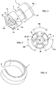
- connecting devices 1 each having a lock 5 more particularly illustrated on the Figures 2 and 3 .
- the latch 5 comprises three radial fins 6a to 6c and extends longitudinally in an axial direction III-III.
- Each latch 5 is mounted in the dental prosthesis 3 by means of a compressible retaining ring 7 as shown in FIG. figure 4 .
- the retaining ring 7 is provided with a substantially radial slot 8 which allows it to be mounted by clipping on the lock 5.
- the retaining ring 7 is mounted in an outer peripheral groove 9 formed on the latch 5.
- the latch 5 is intended to be rotatably mounted and to be retained in translation in the dental prosthesis 3 in a receiving housing 10.
- the receiving housing 10 has an inner peripheral groove 11.
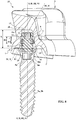
- the receiving housing 10 has, in its lower part, an annular shoulder 12 so that the receiving housing 10 has in the lower part a lower orifice 14 of smaller cross-section than the outer diameter of the retaining ring 7. Thanks to its compressible nature, the retaining ring 7 can decrease in outer diameter to penetrate into the lower orifice 14 and pass the shoulder 12 by more closely enclosing the bottom of the outer peripheral groove 9. Once the lock 5 provided with its retaining ring 7 has been inserted axially into the receiving housing 10, the retaining ring 7 opens radially and simultaneously engages in the outer peripheral groove 9 and in the inner peripheral groove 11. The latch 5 is thus retained captive in the dental prosthesis 3.
- axial channels 13 are provided, illustrated in broken lines on the figure 5 , extending from the lower orifice 14 of the receiving housing 10 to the inner peripheral groove 11.
- a removal tool of the retaining ring 7 can thus be brought around the retaining ring 7 in order to compress it and to reduce the outer diameter to extract it through the lower orifice 14.
- the latch 5 is intended to cooperate directly with a dental implant 2a or 2b as illustrated in FIGS. Figures 6 and 7 .
- the implant 2a or 2b comprises a retaining cavity 15 with three protruding protuberances 16a to 16c extending radially towards the center of the retaining cavity 15.
- the radial fins 6a to 6c and the protruding protuberances 16a to 16c are shaped and dimensioned so as to cooperate by rotation of the latch 5 to retain the dental prosthesis 3 trans-fixed on the dental implant 2.
- the radial fins 6a to 6c and protruding protuberances 16a to 16c are dimensionally shaped so as to allow penetration of the latch 5 and its radial fins 6a to 6c in the retaining cavity 15 by a simple axial translational movement illustrated by the arrow 170 on the figure 7 .
- the radial vanes 6a to 6c of the latch 5 are separated from each other by angular sectors 60a to 60c sized so as to pass a protruding protrusion 16a, 16b or 16c during the axial translation movement 170.
- the projections protrusions 16a to 16c of the retaining cavity 15 are separated from each other by angular sectors 160a to 160c sized so as to let a radial fin 6a, 6b or 6c during the simple axial translation movement 170.
- the angular sectors 60a to 60c extend angularly along 70 °
- the radial fins 6a to 6c extending angularly at 50 °.
- the angular sectors 160a to 160c extend angularly along 80 °
- the protruding protuberances 16a to 16c extend angularly along 40 °.
- first end section 5a This form of first end section 5a allows a relative centering between the latch 5 and the retaining cavity 15.
- the latch 5 comprises, at a second end 5b, a cavity 17 allowing its driving in rotation in the axial direction III-III with the aid of a tool.
- the imprint 17 is polygonal.
- the footprint 17 could, however, have any form of non-circular cross section adapted.
- the footprint 17 can in particular be designed according to the teachings of the document EP 2,607,722 A1 to allow the use of a rotational drive tool allowing a patella effect.
- the rotating tool may be specifically adapted to rotate the latch 5 by accessing the cavity 17 via the access channel 18 which extends in an axial direction IV-IV or oblique VV with respect to the axial direction III-III ( figure 5 ) and oblique with the generally flat bearing surface P of the dental prosthesis 3.
- the radial fins 6a to 6c comprise a bearing surface 19 with a progressive ramp 20 intended to bear against a protruding protrusion 16a, 16b or 16c of the holding cavity 15.
- the progressive ramp 20 of the radial fins 6a to 6c allows the ensure good radial guidance and good axial plating of the dental prosthesis 3 against the implant 2.
- protruding protuberances 16a to 16c may comprise a retaining facet 21 with a progressive ramp intended to bear against a radial fin 6a to 6c of latch 5.
- the prostheticist uses a dentist's impression to identify the directions II and II-II according to which the teeth are oriented. implants 2a and 2b.
- the prosthetist may plan to orient the locks 5 with respect to the dental prosthesis 3 so as to make the axial elongation directions III-III of the locks 5 coincide with the axial directions II and II-II, while placing the access channels 18 oriented in the respective directions IV-IV and VV so as to provide access to the latches 5 and to allow a rotation drive of the latches 5 in the axial directions III-III by means of a tool d rotational drive allowing a patella effect.
- the swivel effect allows a great freedom of choice of the angles between the axial directions I-I and V-V on the one hand and II-II and IV-IV on the other hand.
- the prosthetist can thus place the access channels 18 so that they do not open onto an active tooth surface area intended to withstand heavy chewing efforts.
- the dental prosthesis 3 manufactured by the prosthetist it is sent to the dentist to be fixed in the patient's mouth on the dental implants 2a and 2b.
- the dentist begins by placing the dental prosthesis 3 on the dental arch of the patient to verify the adequacy of the dental prosthesis 3 with the space in the mouth.
- the locks 5 are in their longitudinal direction III-III coaxial with the axial directions I-I and II-II.
- the latch 5 and its radial vanes 6a to 6c penetrate into the retaining cavity 15 by a simple axial translation movement during the positioning of the dental prosthesis 3 on the dental arch of the patient.
- the dental prosthesis 3 can thus satisfactorily come to rest along the entire length of the dental arch of the patient.
- the dentist rotates the latches 5 by means of a rotary drive tool which he inserts into the access channels 18 along the axial directions IV-IV and VV.
- the rotary drive tool is shaped so as to enable the latch 5 to be rotated with a ball-and-socket effect as described for example in the document EP 2,607,722 A1 .
- the radial vanes 6a to 6c are at least partially in correspondence with the protruding protuberances 16a to 16c.
- the inner peripheral groove 11 has a height H1 slightly greater than the height H2 of the retaining ring 7 This difference between the heights H1 and H2 induces an axial play j in translation between the dental prosthesis 3 and the locks 5.
- the axial clearance j and the length L of the receiving housing 10 are dimensioned so as to allow a displacement lock 5 in the dental prosthesis 3 so that it does not prevent a satisfactory positioning of the dental prosthesis 3 on the dental arch of the patient.
- the clearance j and the length L are also dimensioned so that the rotary drive tool can always effectively drive the latch 5 in rotation in the axial direction III-III while being inserted in the access channel 18 oriented in the axial direction IV-IV, despite the decline of the lock 5.
- FIGS. 9 to 15 illustrate a dental prosthetic assembly 27 according to a second embodiment according to the invention.
- the latch 5 is rotatably mounted and captive on the dental implant 2a or 2b.
- the dental implant 2a or 2b has an inner peripheral groove 22 of circular cross section, located in the inner part of the receiving cavity 150 formed in the dental implant 2a or 2b.
- the latch 5 comprises meanwhile, at its second end 5b, latching means 23 for penetrating the inner peripheral groove 22 of the receiving cavity 150.
- the latching means 23 comprise three fins 24a to 24c with free ends 240a to 240c with radial elastic displacement.
- the free ends 240a to 240c are also provided with ribs 241a to 241c intended to snap into the inner peripheral groove 22 and be retained by a shoulder 25 located above the inner peripheral groove 22.
- the polygonal cavity 17, for rotating the latch 5 extends longitudinally through the latch 5 over its length along its axial direction III-III and thus opens at the first end 5a of the latch 5.
- the dental prosthesis 3 is provided with the retaining cavity 15, as illustrated in FIGS. Figures 12 to 14 .
- the radial fins 6a to 6c and the protruding protuberances 16a to 16c are shaped in a manner similar to that explained with respect to the first embodiment of the invention illustrated in FIGS. Figures 1 to 8 .
- the connecting device 1 used in the second embodiment of the invention is similar to that explained in connection with the first embodiment of the invention, except that it is here the cavity of retainer 15 which is formed in the dental prosthesis 3 so as to be oriented in the patient's mouth in an axial direction VI-VI coaxial with the axial directions II or II-II dental implants 2a and 2b.
- the latch 5 is in turn arranged with its longitudinal direction III-III coinciding with the axial direction I-I or II-II dental implants 2a and 2b.
- the dentist When fixing the dental prosthesis 3 on the dental implants 2a and 2b, the dentist reports locks 5 in the upper part of the implants 2a and 2b by snapping. The dentist then places the dental prosthesis 3 on the dental arch of the patient. This pose is done perfectly if the radial vanes 6a to 6c are not in correspondence of protruding protuberances 16a to 16c. If this is not the case, the dentist slightly rotates the latches 5 using a rotational drive tool inserted in the access channels 18 to arrange the radial fins 6a to 6c in correspondence angular sectors 160a to 160c.
- the dentist then drives the latches 5 in rotation in their longitudinal direction III-III so as to cooperate the support facets 19 of the radial vanes 6a to 6c with the retaining facets 21 protruding protrusions 16a to 16c.
- the dentist introduces a rotational drive tool into the cavity 17 by passing through the access channel 18 and through the retaining cavity 15.
- the dentist inserts into the impression 17 the locking piece 26 illustrated on the figure 15 , which has an outer shape complementary to the inner shape of the footprint 17.
- the locking piece 26 has dimensions allowing insertion slightly in force in the footprint 17 of the latch 5. Once in place, as shown in FIG. figure 14 , the locking piece 26 prevents any centripetal radial bending of the elastic fins 24a to 24c, so that the ribs 241a to 241c remain well in position. position in the inner peripheral groove 22 located in the receiving cavity 150 formed in the dental implant 2a and 2b.
- trans-fixed type implant-borne multiple prosthesis that is to say fixed to several implants in the jaw of the patient
- the invention can also be used for a unitary prosthesis.
- implant-type trans-fixed type that is to say, attached to a single implant in the jaw of the patient.
- the connecting device according to the invention nevertheless has significant additional advantages in the case of a dental prosthetic assembly 27 comprising an implant-borne plural trans-fixed dental prosthesis 3 carried on a plurality of dental implants 2a and 2b, in particular during the placing phase of the dental prosthesis 3 on the dental arch of the patient.
- the implant-borne plural trans-fixed dental prosthesis 3 may include a connecting bar for mechanically interconnecting the dental implants on which the dental prosthesis 3 is fixed. In the embodiments illustrated in the figures, the dental prosthesis 3 has no link bar
Landscapes
- Health & Medical Sciences (AREA)
- Oral & Maxillofacial Surgery (AREA)
- Orthopedic Medicine & Surgery (AREA)
- Dentistry (AREA)
- Epidemiology (AREA)
- Life Sciences & Earth Sciences (AREA)
- Animal Behavior & Ethology (AREA)
- General Health & Medical Sciences (AREA)
- Public Health (AREA)
- Veterinary Medicine (AREA)
- Dental Prosthetics (AREA)
Claims (11)
- Zahnprothesenaufbau (27), umfassend:- ein Zahnimplantat (2a, 2b),- eine Zahnprothese (3),- eine Anschlussvorrichtung (1) umfassend eine Rückhaltekavität (15), die entweder im Zahnimplantat (2a, 2b) oder in der Zahnprothese (3) ausgebildet ist, und die auf ihrer Außenseite mit vorspringenden Höckern (16a-16c) ausgestattet ist, die sich radial entgegen einem Zentrum der Rückhaltekavität (15) erstrecken,dadurch gekennzeichnet, dass:- wobei die Zahnprothese (3) nach transfixierter Art aufgebaut ist,- die Anschlussvorrichtung (1) einen Riegel (5) umfasst, der wenigstens zwei radiale Flügel (6a-6c) aufweist und drehbar sowie translatorisch zurückgehalten am entsprechend anderen Teil, dem Zahnimplantat (2a, 2b) oder der Zahnprothese (3) befestigt ist, wobei die radialen Flügel (6a-6c) und die vorspringenden Höcker (16a-16c) eingerichtet und aufgebaut sind, dem Riegel (5) und seinen radialen Flügeln (6a-6c) durch eine Bewegung axialer Translation (170) in die Rückhaltekavität (15) einzudringen,- die radialen Flügel (6a-6c) und die vorspringenden Höcker (16a-16c) eingerichtet und aufgebaut sind, durch eine Drehung des Riegels (5) zusammenzuwirken, um die Zahnprothese (3) aufgesteckt auf dem Zahnimplantat (2a, 2b) zu halten.
- Zahnprothesenaufbau (27) nach Anspruch 1, dadurch gekennzeichnet, dass:- die radialen Flügel (6a-6c) des Riegels (5) voneinander über winklige Sektoren (60a-60c) getrennt sind, die derart aufgebaut sind, dass einem vorspringenden Höcker (16a-16c) ermöglicht wird, durch eine einfache Bewegung axialer Translation (170) hindurchzudringen,- die vorspringenden Höcker (16a-16c) der Rückhaltekavität (15) voneinander über winklige Sektoren (160a-160c) getrennt sind, die derart aufgebaut sind, dass einem radialen Flügel (6a-6c) ermöglicht wird, während der genannten einfachen Bewegung axialer Translation (170) hindurchzudringen.
- Zahnprothesenaufbau (27) nach irgendeinem der Ansprüche 1 oder 2, dadurch gekennzeichnet, dass die radialen Flügel (6a-6c) des Riegels (5) an einem Bereich eines ersten Endes (5a) getragen sind, der im Wesentlichen kegelförmig oder kegelstumpfförmig ist.
- Zahnprothesenaufbau (27) nach irgendeinem der vorstehenden Ansprüche 1 bis 3, dadurch gekennzeichnet, dass der Riegel (5) einen Sockel (17) besitzt, der es ihm ermöglicht mithilfe eines Werkzeuges gedreht angetrieben zu werden.
- Zahnprothesenaufbau (27) nach irgendeinem der vorstehenden Ansprüche 1 bis 4, dadurch gekennzeichnet, dass die radialen Flügel (6a-6c) eine Lagerfacette (19) mit einer progressiven Rampe (20) zum Lagern gegen einen vorspringenden Höcker (16a-16c) der Rückhaltekavität (15) besitzen und/oder dass die vorspringenden Höcker (16a-16c) eine Rückhaltefacette (21) mit einer progressiven Rampe zum Lagern gegen einen radialen Flügel (6a-6c) des Riegels (5) besitzen.
- Zahnprothesenaufbau (27) nach irgendeinem der vorstehenden Ansprüche 1 bis 5, dadurch gekennzeichnet, dass der Riegel (5) drehbar und translatorisch zurückgehalten in der Zahnprothese (3) über einen kompressiblen Rückhaltering (7), vorzugsweise mittels eines Schlitzes (8), gehalten ist, der gleichzeitig in eine äußere Außenspalte (9), die auf dem Riegel (5) ausgebildet ist und in eine innere Außenspalte (11), die auf der Zahnprothese (3) ausgebildet ist, eingreift.
- Zahnprothesenaufbau (27) nach Anspruch 6, dadurch gekennzeichnet, dass die Zahnprothese (3) eine Vielzahl von axialen Öffnungskanälen (13) besitzt, die sich bis zur inneren Außenspalte (11) erstrecken, die in der inneren Zahnprothese (3) ausgebildet ist.
- Zahnprothesenaufbau (27) nach Anspruch 6 oder 7, dadurch gekennzeichnet, dass die inner Außenspalte (11), die in der Zahnprothese (3) ausgebildet ist, und/oder die äußere Außenspalte (9), die auf dem Riegel (5) ausgebildet ist, eine Höhe (H1) besitzen, die leicht größer ist, als die (H2) des Rückhalteringes (7), was ein Axialspiel (j) in der Bewegung zwischen der Zahnprothese (3) und dem Riegel (5) ermöglicht.
- Zahnprothesenaufbau (27) nach irgendeinem der vorstehenden Ansprüche 1 bis 5, dadurch gekennzeichnet, dass der Riegel (5) drehbar und in translatorisch zurückgehalten im Zahnimplantat (2a, 2b) gehalten ist, durch:- eine innere Außenspalte (22), die sich in einer Aufnahmeausnehmung (150) befindet, die im Zahnimplantat (2a, 2b) ausgebildet ist,- ein zweites Ende (5b) des Riegels (5) Schnappverbindungsmittel (23) zum Eindringen in die innere Außenspalte (22) der Aufnahmeausnehmung (150) besitzt.
- Zahnprothesenaufbau (27) nach irgendeinem der vorstehenden Ansprüche 1 bis 9, dadurch gekennzeichnet, dass- er eine Vielzahl von Zahnimplantaten (2a, 2b) aufweist,- die transfixierte Zahnprothese (3) eine implantatgestützte multiple Prothese ist.
- Zahnprothesenaufbau (27) nach irgendeinem der vorstehenden Ansprüche 1 bis 10, dadurch gekennzeichnet, dass die Zahnprothese (3) wenigstens einen Zugangskanal (18) umfasst, der in einer Richtung (IV-IV, V-V) ausgerichtet ist, die zur im Wesentlichen ebenen Allgemeinlageroberfläche (P) der Zahnprothese (3) schräg steht.
Applications Claiming Priority (1)
| Application Number | Priority Date | Filing Date | Title |
|---|---|---|---|
| FR1360411A FR3012319B1 (fr) | 2013-10-25 | 2013-10-25 | Dispositif de liaison entre un implant dentaire et une prothese dentaire trans-fixee |
Publications (2)
| Publication Number | Publication Date |
|---|---|
| EP2865353A1 EP2865353A1 (de) | 2015-04-29 |
| EP2865353B1 true EP2865353B1 (de) | 2018-06-27 |
Family
ID=49713366
Family Applications (1)
| Application Number | Title | Priority Date | Filing Date |
|---|---|---|---|
| EP14189176.2A Active EP2865353B1 (de) | 2013-10-25 | 2014-10-16 | Zahnprothesenanordnung, die ein Zahnimplantat und eine feste Zahnprothese umfasst |
Country Status (7)
| Country | Link |
|---|---|
| US (1) | US9579169B2 (de) |
| EP (1) | EP2865353B1 (de) |
| JP (1) | JP5925276B2 (de) |
| CN (1) | CN104546163B (de) |
| BR (1) | BR102014026897A2 (de) |
| ES (1) | ES2681596T3 (de) |
| FR (1) | FR3012319B1 (de) |
Families Citing this family (16)
| Publication number | Priority date | Publication date | Assignee | Title |
|---|---|---|---|---|
| US8747112B2 (en) | 2011-12-30 | 2014-06-10 | Nobel Biocare Services Ag | Abutment position locator |
| FR3033692A1 (fr) * | 2015-03-17 | 2016-09-23 | Anthogyr Sa | Prothese dentaire plurale transfixee |
| FR3035786A1 (fr) * | 2015-05-06 | 2016-11-11 | Anthogyr Sa | Dispositif de liaison entre une prothese dentaire et un maitre-modele |
| DE102015006146A1 (de) * | 2015-05-12 | 2016-11-17 | Thomas Jehle | Friktionselement |
| CA2988567C (en) | 2015-06-08 | 2021-08-31 | Biomet 3I, Llc | Screwless dental implant connection |
| TW201808233A (zh) * | 2016-06-02 | 2018-03-16 | 康洛格生物科技公司 | 保持器、包裝與保持器之組合體、手術裝置用轉接器及具有支撐結構的手術裝置用保持器 |
| DE102016215427A1 (de) * | 2016-08-17 | 2018-02-22 | Holger Zipprich | Dental-Prothetiksystem und prothetische Konstruktion zur Verwendung mit einem in den Kieferknochen eines Patienten inserierten Dentalimplantat |
| WO2019109320A1 (zh) * | 2017-12-08 | 2019-06-13 | 辰庚事业股份有限公司 | 具直立式骨梁结构之人工牙体 |
| EP3632367A1 (de) * | 2018-10-03 | 2020-04-08 | Nobel Biocare Services AG | Zahnkomponente mit einer halteschnittstelle |
| KR101966407B1 (ko) * | 2018-11-21 | 2019-04-05 | 주식회사 하이니스 | 어버트먼트 조립체 |
| IL266021A (en) * | 2019-04-14 | 2020-10-28 | Mikambeh Ltd | Dental adapter and method |
| BE1028266B1 (nl) * | 2020-05-05 | 2021-12-07 | Bvba Dr Van Doorne Luc | Baar, samenstel van een overkappingsprothese en een baar, overkappingsprothese |
| KR102454967B1 (ko) * | 2022-01-05 | 2022-10-13 | 김경록 | 치과 임플란트 시스템 |
| KR102483796B1 (ko) * | 2022-01-26 | 2023-01-03 | 주식회사 씨앤지치과기공소 | 치과 임플란트용 어버트먼트 |
| KR102636643B1 (ko) * | 2023-04-27 | 2024-02-13 | 신동현 | 치과 임플란트의 상부 구조물 |
| KR102769652B1 (ko) * | 2024-12-16 | 2025-02-17 | 김경록 | 시멘트리스 치과 임플란트 시스템 |
Citations (1)
| Publication number | Priority date | Publication date | Assignee | Title |
|---|---|---|---|---|
| EP1972297A1 (de) * | 2007-03-19 | 2008-09-24 | Straumann Holding AG | Zweiteilige Schraube für ein Dentalimplantat |
Family Cites Families (14)
| Publication number | Priority date | Publication date | Assignee | Title |
|---|---|---|---|---|
| JPS5035952U (de) * | 1973-07-31 | 1975-04-16 | ||
| JPS58191413U (ja) * | 1982-06-15 | 1983-12-20 | 日本工機株式会社 | ボルト・ナツト |
| ATE230241T1 (de) * | 1997-03-27 | 2003-01-15 | Cendres & Metaux Sa | Vorrichtung zur abnehmbaren befestigung von zahnprothesen |
| IT1311004B1 (it) * | 1999-03-16 | 2002-02-27 | Antonio Gallicchio | Impianto per denti artificiali. |
| IL148509A0 (en) * | 1999-09-22 | 2002-09-12 | Lipat Consulting Ag | Screw-type intraossal dental implant |
| EP2046238B1 (de) * | 2006-08-01 | 2015-06-17 | BONDAR, Vitali | Zahnimplantatsystem |
| US7704076B2 (en) * | 2006-12-20 | 2010-04-27 | Zest Ip Holdings Llc | Dental attachment assembly and method |
| DK1992304T3 (da) * | 2007-05-12 | 2010-12-20 | Gerd Axel Dr Walther | Tandimplantat, især af et keramikmateriale |
| ES2447941T3 (es) * | 2009-02-26 | 2014-03-13 | Nobel Biocare Services Ag | Conjunto de implante dental |
| CH704382A1 (de) * | 2011-01-25 | 2012-07-31 | Dentalpoint Ag | Zahnersatz-System. |
| JP5100918B2 (ja) * | 2011-03-28 | 2012-12-19 | 株式会社T・U・M | 義歯システム、入れ歯の作成方法および補修方法 |
| EP2607722B1 (de) * | 2011-12-22 | 2014-02-26 | Straumann Holding AG | Verbindungsschraube für ein Dentalimplantat |
| KR101311250B1 (ko) * | 2012-04-06 | 2013-09-27 | 김만용 | 틀니용 어태치먼트 |
| EP2653131B1 (de) * | 2012-04-19 | 2018-02-28 | Dentsply IH AB | Zahnimplantatset |
-
2013
- 2013-10-25 FR FR1360411A patent/FR3012319B1/fr not_active Expired - Fee Related
-
2014
- 2014-10-15 US US14/515,049 patent/US9579169B2/en active Active
- 2014-10-16 ES ES14189176.2T patent/ES2681596T3/es active Active
- 2014-10-16 EP EP14189176.2A patent/EP2865353B1/de active Active
- 2014-10-23 JP JP2014215961A patent/JP5925276B2/ja active Active
- 2014-10-27 BR BR102014026897A patent/BR102014026897A2/pt active Search and Examination
- 2014-10-27 CN CN201410584697.1A patent/CN104546163B/zh active Active
Patent Citations (1)
| Publication number | Priority date | Publication date | Assignee | Title |
|---|---|---|---|---|
| EP1972297A1 (de) * | 2007-03-19 | 2008-09-24 | Straumann Holding AG | Zweiteilige Schraube für ein Dentalimplantat |
Also Published As
| Publication number | Publication date |
|---|---|
| FR3012319A1 (fr) | 2015-05-01 |
| US9579169B2 (en) | 2017-02-28 |
| FR3012319B1 (fr) | 2016-09-02 |
| CN104546163B (zh) | 2017-06-13 |
| US20150118651A1 (en) | 2015-04-30 |
| CN104546163A (zh) | 2015-04-29 |
| ES2681596T3 (es) | 2018-09-14 |
| EP2865353A1 (de) | 2015-04-29 |
| BR102014026897A2 (pt) | 2016-01-05 |
| JP2015083129A (ja) | 2015-04-30 |
| JP5925276B2 (ja) | 2016-05-25 |
Similar Documents
| Publication | Publication Date | Title |
|---|---|---|
| EP2865353B1 (de) | Zahnprothesenanordnung, die ein Zahnimplantat und eine feste Zahnprothese umfasst | |
| EP1065984B1 (de) | Osteosynthetische verbindungsvorrichtung | |
| EP3573568B1 (de) | Komponentensatz für die zahnärztliche zahnrestauration | |
| CH663349A5 (fr) | Structure de fixation dentaire. | |
| EP2456388A2 (de) | Ergänzende stabilisierungsvorrichtung für ein knocheninternes zahnimplantat | |
| EP1034750A1 (de) | Verhindern der Drehbewegung von Suprakonstruktionen bei Zahnimplantaten | |
| WO2010061124A1 (fr) | Dispositif d'aide a la pose d'implants dentaires | |
| WO2004093714A1 (fr) | Procede de fixation reversible d’un outil sur un element implantable et dispositif pour la mise en oeuvre d’un tel procede de fixation | |
| EP3069682B1 (de) | Anordnung, die ein werkstück und eine axiale anschlagvorrichtung umfasst, zum anbringen in eine ausbohrung dieses werkstücks | |
| EP2685929B2 (de) | Zahnimplantat | |
| EP3151787B1 (de) | Chirurgisches implantat und zugehöriges installationswerkzeug, chirurgisches kit und verfahren zur herstellung | |
| FR3033692A1 (fr) | Prothese dentaire plurale transfixee | |
| WO2008062367A2 (fr) | Dispositif d'impression a coiffe de prise d'empreinte pour prothese dentaire | |
| EP2184083B1 (de) | Transkraniale Befestigungsvorrichtung für Sonde zur Tiefenstimulation des Gehirns | |
| WO2019081059A1 (fr) | Ensemble d'implantation dentaire endo-osseux | |
| EP3069683B1 (de) | Transfixierte multiple zahnprothese | |
| CH666804A5 (fr) | Tete de contre-angle ou de turbine d'une piece a main dentaire. | |
| EP4478994B1 (de) | Implantatvorrichtung zur durchführung einer posterioren wirbelsäulenarthrodese an einem facettengelenk und system mit dem implantat und seinem positionierwerkzeug | |
| EP4059469B1 (de) | Dentale untergruppe für die einheitliche prothetische versorgung eines zahns, zugehörige zahnbaugruppe und montageverfahren | |
| WO2012010794A1 (fr) | Implant dentaire et dispositif d'entrainement en rotation dudit implant dentaire | |
| FR3012318A1 (fr) | Dispositif de liaison angule | |
| FR3036032A1 (fr) | Pilier dentaire a frein de vis et prothese dentaire utilisant un tel pilier | |
| FR3142081A1 (fr) | Cage apte à être implantée entre deux portions osseuses, | |
| FR3038219A1 (fr) | Dispositif de transfert angule | |
| FR3145862A1 (fr) | Dispositif prothetique dentaire comprenant une piece de liaison deformable |
Legal Events
| Date | Code | Title | Description |
|---|---|---|---|
| PUAI | Public reference made under article 153(3) epc to a published international application that has entered the european phase |
Free format text: ORIGINAL CODE: 0009012 |
|
| 17P | Request for examination filed |
Effective date: 20141016 |
|
| AK | Designated contracting states |
Kind code of ref document: A1 Designated state(s): AL AT BE BG CH CY CZ DE DK EE ES FI FR GB GR HR HU IE IS IT LI LT LU LV MC MK MT NL NO PL PT RO RS SE SI SK SM TR |
|
| AX | Request for extension of the european patent |
Extension state: BA ME |
|
| R17P | Request for examination filed (corrected) |
Effective date: 20151027 |
|
| RBV | Designated contracting states (corrected) |
Designated state(s): AL AT BE BG CH CY CZ DE DK EE ES FI FR GB GR HR HU IE IS IT LI LT LU LV MC MK MT NL NO PL PT RO RS SE SI SK SM TR |
|
| GRAP | Despatch of communication of intention to grant a patent |
Free format text: ORIGINAL CODE: EPIDOSNIGR1 |
|
| RIC1 | Information provided on ipc code assigned before grant |
Ipc: A61C 13/265 20060101ALN20171031BHEP Ipc: A61C 8/00 20060101AFI20171031BHEP |
|
| INTG | Intention to grant announced |
Effective date: 20171206 |
|
| GRAJ | Information related to disapproval of communication of intention to grant by the applicant or resumption of examination proceedings by the epo deleted |
Free format text: ORIGINAL CODE: EPIDOSDIGR1 |
|
| GRAP | Despatch of communication of intention to grant a patent |
Free format text: ORIGINAL CODE: EPIDOSNIGR1 |
|
| INTC | Intention to grant announced (deleted) | ||
| GRAS | Grant fee paid |
Free format text: ORIGINAL CODE: EPIDOSNIGR3 |
|
| RIC1 | Information provided on ipc code assigned before grant |
Ipc: A61C 13/265 20060101ALN20180417BHEP Ipc: A61C 8/00 20060101AFI20180417BHEP |
|
| GRAA | (expected) grant |
Free format text: ORIGINAL CODE: 0009210 |
|
| INTG | Intention to grant announced |
Effective date: 20180504 |
|
| AK | Designated contracting states |
Kind code of ref document: B1 Designated state(s): AL AT BE BG CH CY CZ DE DK EE ES FI FR GB GR HR HU IE IS IT LI LT LU LV MC MK MT NL NO PL PT RO RS SE SI SK SM TR |
|
| REG | Reference to a national code |
Ref country code: GB Ref legal event code: FG4D Free format text: NOT ENGLISH |
|
| REG | Reference to a national code |
Ref country code: AT Ref legal event code: REF Ref document number: 1011627 Country of ref document: AT Kind code of ref document: T Effective date: 20180715 |
|
| REG | Reference to a national code |
Ref country code: DE Ref legal event code: R096 Ref document number: 602014027470 Country of ref document: DE |
|
| REG | Reference to a national code |
Ref country code: IE Ref legal event code: FG4D Free format text: LANGUAGE OF EP DOCUMENT: FRENCH |
|
| REG | Reference to a national code |
Ref country code: CH Ref legal event code: NV Representative=s name: WEINMANN ZIMMERLI, CH |
|
| REG | Reference to a national code |
Ref country code: ES Ref legal event code: FG2A Ref document number: 2681596 Country of ref document: ES Kind code of ref document: T3 Effective date: 20180914 |
|
| REG | Reference to a national code |
Ref country code: SE Ref legal event code: TRGR |
|
| REG | Reference to a national code |
Ref country code: FR Ref legal event code: PLFP Year of fee payment: 5 |
|
| PG25 | Lapsed in a contracting state [announced via postgrant information from national office to epo] |
Ref country code: FI Free format text: LAPSE BECAUSE OF FAILURE TO SUBMIT A TRANSLATION OF THE DESCRIPTION OR TO PAY THE FEE WITHIN THE PRESCRIBED TIME-LIMIT Effective date: 20180627 Ref country code: LT Free format text: LAPSE BECAUSE OF FAILURE TO SUBMIT A TRANSLATION OF THE DESCRIPTION OR TO PAY THE FEE WITHIN THE PRESCRIBED TIME-LIMIT Effective date: 20180627 Ref country code: BG Free format text: LAPSE BECAUSE OF FAILURE TO SUBMIT A TRANSLATION OF THE DESCRIPTION OR TO PAY THE FEE WITHIN THE PRESCRIBED TIME-LIMIT Effective date: 20180927 Ref country code: NO Free format text: LAPSE BECAUSE OF FAILURE TO SUBMIT A TRANSLATION OF THE DESCRIPTION OR TO PAY THE FEE WITHIN THE PRESCRIBED TIME-LIMIT Effective date: 20180927 |
|
| REG | Reference to a national code |
Ref country code: NL Ref legal event code: MP Effective date: 20180627 |
|
| REG | Reference to a national code |
Ref country code: LT Ref legal event code: MG4D |
|
| PG25 | Lapsed in a contracting state [announced via postgrant information from national office to epo] |
Ref country code: GR Free format text: LAPSE BECAUSE OF FAILURE TO SUBMIT A TRANSLATION OF THE DESCRIPTION OR TO PAY THE FEE WITHIN THE PRESCRIBED TIME-LIMIT Effective date: 20180928 Ref country code: RS Free format text: LAPSE BECAUSE OF FAILURE TO SUBMIT A TRANSLATION OF THE DESCRIPTION OR TO PAY THE FEE WITHIN THE PRESCRIBED TIME-LIMIT Effective date: 20180627 Ref country code: HR Free format text: LAPSE BECAUSE OF FAILURE TO SUBMIT A TRANSLATION OF THE DESCRIPTION OR TO PAY THE FEE WITHIN THE PRESCRIBED TIME-LIMIT Effective date: 20180627 Ref country code: LV Free format text: LAPSE BECAUSE OF FAILURE TO SUBMIT A TRANSLATION OF THE DESCRIPTION OR TO PAY THE FEE WITHIN THE PRESCRIBED TIME-LIMIT Effective date: 20180627 |
|
| REG | Reference to a national code |
Ref country code: AT Ref legal event code: MK05 Ref document number: 1011627 Country of ref document: AT Kind code of ref document: T Effective date: 20180627 |
|
| PG25 | Lapsed in a contracting state [announced via postgrant information from national office to epo] |
Ref country code: NL Free format text: LAPSE BECAUSE OF FAILURE TO SUBMIT A TRANSLATION OF THE DESCRIPTION OR TO PAY THE FEE WITHIN THE PRESCRIBED TIME-LIMIT Effective date: 20180627 |
|
| PG25 | Lapsed in a contracting state [announced via postgrant information from national office to epo] |
Ref country code: SK Free format text: LAPSE BECAUSE OF FAILURE TO SUBMIT A TRANSLATION OF THE DESCRIPTION OR TO PAY THE FEE WITHIN THE PRESCRIBED TIME-LIMIT Effective date: 20180627 Ref country code: RO Free format text: LAPSE BECAUSE OF FAILURE TO SUBMIT A TRANSLATION OF THE DESCRIPTION OR TO PAY THE FEE WITHIN THE PRESCRIBED TIME-LIMIT Effective date: 20180627 Ref country code: CZ Free format text: LAPSE BECAUSE OF FAILURE TO SUBMIT A TRANSLATION OF THE DESCRIPTION OR TO PAY THE FEE WITHIN THE PRESCRIBED TIME-LIMIT Effective date: 20180627 Ref country code: PL Free format text: LAPSE BECAUSE OF FAILURE TO SUBMIT A TRANSLATION OF THE DESCRIPTION OR TO PAY THE FEE WITHIN THE PRESCRIBED TIME-LIMIT Effective date: 20180627 Ref country code: AT Free format text: LAPSE BECAUSE OF FAILURE TO SUBMIT A TRANSLATION OF THE DESCRIPTION OR TO PAY THE FEE WITHIN THE PRESCRIBED TIME-LIMIT Effective date: 20180627 Ref country code: EE Free format text: LAPSE BECAUSE OF FAILURE TO SUBMIT A TRANSLATION OF THE DESCRIPTION OR TO PAY THE FEE WITHIN THE PRESCRIBED TIME-LIMIT Effective date: 20180627 Ref country code: IS Free format text: LAPSE BECAUSE OF FAILURE TO SUBMIT A TRANSLATION OF THE DESCRIPTION OR TO PAY THE FEE WITHIN THE PRESCRIBED TIME-LIMIT Effective date: 20181027 |
|
| PG25 | Lapsed in a contracting state [announced via postgrant information from national office to epo] |
Ref country code: SM Free format text: LAPSE BECAUSE OF FAILURE TO SUBMIT A TRANSLATION OF THE DESCRIPTION OR TO PAY THE FEE WITHIN THE PRESCRIBED TIME-LIMIT Effective date: 20180627 |
|
| REG | Reference to a national code |
Ref country code: DE Ref legal event code: R097 Ref document number: 602014027470 Country of ref document: DE |
|
| PLBE | No opposition filed within time limit |
Free format text: ORIGINAL CODE: 0009261 |
|
| STAA | Information on the status of an ep patent application or granted ep patent |
Free format text: STATUS: NO OPPOSITION FILED WITHIN TIME LIMIT |
|
| PG25 | Lapsed in a contracting state [announced via postgrant information from national office to epo] |
Ref country code: DK Free format text: LAPSE BECAUSE OF FAILURE TO SUBMIT A TRANSLATION OF THE DESCRIPTION OR TO PAY THE FEE WITHIN THE PRESCRIBED TIME-LIMIT Effective date: 20180627 |
|
| 26N | No opposition filed |
Effective date: 20190328 |
|
| PG25 | Lapsed in a contracting state [announced via postgrant information from national office to epo] |
Ref country code: SI Free format text: LAPSE BECAUSE OF FAILURE TO SUBMIT A TRANSLATION OF THE DESCRIPTION OR TO PAY THE FEE WITHIN THE PRESCRIBED TIME-LIMIT Effective date: 20180627 |
|
| PG25 | Lapsed in a contracting state [announced via postgrant information from national office to epo] |
Ref country code: AL Free format text: LAPSE BECAUSE OF FAILURE TO SUBMIT A TRANSLATION OF THE DESCRIPTION OR TO PAY THE FEE WITHIN THE PRESCRIBED TIME-LIMIT Effective date: 20180627 |
|
| PG25 | Lapsed in a contracting state [announced via postgrant information from national office to epo] |
Ref country code: MT Free format text: LAPSE BECAUSE OF FAILURE TO SUBMIT A TRANSLATION OF THE DESCRIPTION OR TO PAY THE FEE WITHIN THE PRESCRIBED TIME-LIMIT Effective date: 20180627 |
|
| PG25 | Lapsed in a contracting state [announced via postgrant information from national office to epo] |
Ref country code: TR Free format text: LAPSE BECAUSE OF FAILURE TO SUBMIT A TRANSLATION OF THE DESCRIPTION OR TO PAY THE FEE WITHIN THE PRESCRIBED TIME-LIMIT Effective date: 20180627 |
|
| PG25 | Lapsed in a contracting state [announced via postgrant information from national office to epo] |
Ref country code: PT Free format text: LAPSE BECAUSE OF FAILURE TO SUBMIT A TRANSLATION OF THE DESCRIPTION OR TO PAY THE FEE WITHIN THE PRESCRIBED TIME-LIMIT Effective date: 20180627 |
|
| PG25 | Lapsed in a contracting state [announced via postgrant information from national office to epo] |
Ref country code: HU Free format text: LAPSE BECAUSE OF FAILURE TO SUBMIT A TRANSLATION OF THE DESCRIPTION OR TO PAY THE FEE WITHIN THE PRESCRIBED TIME-LIMIT; INVALID AB INITIO Effective date: 20141016 Ref country code: MK Free format text: LAPSE BECAUSE OF NON-PAYMENT OF DUE FEES Effective date: 20180627 Ref country code: CY Free format text: LAPSE BECAUSE OF FAILURE TO SUBMIT A TRANSLATION OF THE DESCRIPTION OR TO PAY THE FEE WITHIN THE PRESCRIBED TIME-LIMIT Effective date: 20180627 |
|
| P01 | Opt-out of the competence of the unified patent court (upc) registered |
Effective date: 20230519 |
|
| REG | Reference to a national code |
Ref country code: CH Ref legal event code: U11 Free format text: ST27 STATUS EVENT CODE: U-0-0-U10-U11 (AS PROVIDED BY THE NATIONAL OFFICE) Effective date: 20251101 |
|
| PGFP | Annual fee paid to national office [announced via postgrant information from national office to epo] |
Ref country code: LU Payment date: 20251022 Year of fee payment: 12 |
|
| PGFP | Annual fee paid to national office [announced via postgrant information from national office to epo] |
Ref country code: DE Payment date: 20251021 Year of fee payment: 12 |
|
| PGFP | Annual fee paid to national office [announced via postgrant information from national office to epo] |
Ref country code: GB Payment date: 20251022 Year of fee payment: 12 |
|
| PGFP | Annual fee paid to national office [announced via postgrant information from national office to epo] |
Ref country code: MC Payment date: 20251023 Year of fee payment: 12 |
|
| PGFP | Annual fee paid to national office [announced via postgrant information from national office to epo] |
Ref country code: IT Payment date: 20251024 Year of fee payment: 12 |
|
| PGFP | Annual fee paid to national office [announced via postgrant information from national office to epo] |
Ref country code: FR Payment date: 20251030 Year of fee payment: 12 |
|
| PGFP | Annual fee paid to national office [announced via postgrant information from national office to epo] |
Ref country code: BE Payment date: 20251021 Year of fee payment: 12 |
|
| PGFP | Annual fee paid to national office [announced via postgrant information from national office to epo] |
Ref country code: CH Payment date: 20251101 Year of fee payment: 12 Ref country code: SE Payment date: 20251021 Year of fee payment: 12 |
|
| PGFP | Annual fee paid to national office [announced via postgrant information from national office to epo] |
Ref country code: IE Payment date: 20251024 Year of fee payment: 12 |
|
| PGFP | Annual fee paid to national office [announced via postgrant information from national office to epo] |
Ref country code: ES Payment date: 20251210 Year of fee payment: 12 |