EP2865472A1 - Outil d'enlèvement de copeaux et son procédé de refroidissement - Google Patents
Outil d'enlèvement de copeaux et son procédé de refroidissement Download PDFInfo
- Publication number
- EP2865472A1 EP2865472A1 EP20140190354 EP14190354A EP2865472A1 EP 2865472 A1 EP2865472 A1 EP 2865472A1 EP 20140190354 EP20140190354 EP 20140190354 EP 14190354 A EP14190354 A EP 14190354A EP 2865472 A1 EP2865472 A1 EP 2865472A1
- Authority
- EP
- European Patent Office
- Prior art keywords
- coolant
- section
- expansion space
- tool
- cross
- Prior art date
- Legal status (The legal status is an assumption and is not a legal conclusion. Google has not performed a legal analysis and makes no representation as to the accuracy of the status listed.)
- Withdrawn
Links
Images

Classifications
-
- B—PERFORMING OPERATIONS; TRANSPORTING
- B23—MACHINE TOOLS; METAL-WORKING NOT OTHERWISE PROVIDED FOR
- B23Q—DETAILS, COMPONENTS, OR ACCESSORIES FOR MACHINE TOOLS, e.g. ARRANGEMENTS FOR COPYING OR CONTROLLING; MACHINE TOOLS IN GENERAL CHARACTERISED BY THE CONSTRUCTION OF PARTICULAR DETAILS OR COMPONENTS; COMBINATIONS OR ASSOCIATIONS OF METAL-WORKING MACHINES, NOT DIRECTED TO A PARTICULAR RESULT
- B23Q11/00—Accessories fitted to machine tools for keeping tools or parts of the machine in good working condition or for cooling work; Safety devices specially combined with or arranged in, or specially adapted for use in connection with, machine tools
- B23Q11/10—Arrangements for cooling or lubricating tools or work
- B23Q11/1015—Arrangements for cooling or lubricating tools or work by supplying a cutting liquid through the spindle
- B23Q11/1023—Tool holders, or tools in general specially adapted for receiving the cutting liquid from the spindle
-
- B—PERFORMING OPERATIONS; TRANSPORTING
- B23—MACHINE TOOLS; METAL-WORKING NOT OTHERWISE PROVIDED FOR
- B23C—MILLING
- B23C5/00—Milling-cutters
- B23C5/28—Features relating to lubricating or cooling
-
- B—PERFORMING OPERATIONS; TRANSPORTING
- B23—MACHINE TOOLS; METAL-WORKING NOT OTHERWISE PROVIDED FOR
- B23B—TURNING; BORING
- B23B51/00—Tools for drilling machines
- B23B51/06—Drills with lubricating or cooling equipment
-
- B—PERFORMING OPERATIONS; TRANSPORTING
- B23—MACHINE TOOLS; METAL-WORKING NOT OTHERWISE PROVIDED FOR
- B23D—PLANING; SLOTTING; SHEARING; BROACHING; SAWING; FILING; SCRAPING; LIKE OPERATIONS FOR WORKING METAL BY REMOVING MATERIAL, NOT OTHERWISE PROVIDED FOR
- B23D77/00—Reaming tools
- B23D77/006—Reaming tools with means for lubricating or cooling
-
- B—PERFORMING OPERATIONS; TRANSPORTING
- B23—MACHINE TOOLS; METAL-WORKING NOT OTHERWISE PROVIDED FOR
- B23Q—DETAILS, COMPONENTS, OR ACCESSORIES FOR MACHINE TOOLS, e.g. ARRANGEMENTS FOR COPYING OR CONTROLLING; MACHINE TOOLS IN GENERAL CHARACTERISED BY THE CONSTRUCTION OF PARTICULAR DETAILS OR COMPONENTS; COMBINATIONS OR ASSOCIATIONS OF METAL-WORKING MACHINES, NOT DIRECTED TO A PARTICULAR RESULT
- B23Q11/00—Accessories fitted to machine tools for keeping tools or parts of the machine in good working condition or for cooling work; Safety devices specially combined with or arranged in, or specially adapted for use in connection with, machine tools
- B23Q11/10—Arrangements for cooling or lubricating tools or work
- B23Q11/1038—Arrangements for cooling or lubricating tools or work using cutting liquids with special characteristics, e.g. flow rate, quality
Definitions
- the invention relates to a cutting tool, such as milling or drilling tool or reamer, comprising a tool body with chip area, wherein within the tool body adeffenzulite- and a-ab technicallykanal run as sections of a closed coolant circuit, which extends into the chip area, wherein the coolant supply passage, an expansion space for expanding liquefied gas supplied via the supply passage as a coolant emanates.
- a cutting tool such as milling or drilling tool or reamer
- the invention relates to a method for cooling at least the chip area of a cutting tool, along the longitudinal axis of which a feed and a return duct run as sections of a closed coolant circuit, supply and return ducts are connected to each other in the chip area, wherein the feed channel is a liquefied Gas is supplied as a coolant, and wherein the connection between the supply and the return duct and / or volume of the return duct are designed in terms of volume with respect to the supplied coolant such that this partially evaporated.
- the evaporator cooling has at least one in the interior of the tool or in the vicinity of the functional area to be cooled to an evaporation region, which is suitable for receiving heat in a at least thermally conductive connected to this area functional area, such as a cutting edge.
- the evaporation zone is designed in the form of a throttle.
- machining tool can be used to machine workpieces made of metal and metal alloys, ceramics, wood-, art- or cement-bonded chipboard as well as plastics with and without fiberglass or carbon fiber reinforcement.
- Subject of the DE 197 30 539 C1 is a turning tool comprising a cooling system with channels through which a cooling fluid is fed into the area of a cutting edge.
- a heat sink made of a good thermally conductive material is disposed within the tool, which has a microchannel structure. Water can be used as the cooling fluid.
- the heat sink itself can be part of a closed heat pipe system.
- the present invention is based on the object of further developing a cutting tool and a method for cooling such that, with structurally simple measures, cooling can take place to the required extent in the areas of the tool in which materials are processed. At the same time it should be ensured that a low-energy cooling is possible, with environmental pollution should be excluded.
- the invention provides for a cutting tool of the type mentioned in particular that emanates from the expansion space of the coolant return passage or a portion of the former, wherein cross-section QR of the coolant return channel is greater than the cross-section QZ ofméffenzu meltals is.
- the expansion space can also be at least partially the coolant return channel.
- the evaporation or sublimation of a liquefied gas is used to extract heat from the environment, ie the area of the tool with which machining takes place or in which the tool is guided.
- the expanded refrigerant is then fed via the return channel to a re-liquefying compressor, from which the refrigerant can pass into the feed channel.
- the expansion space or at least a portion thereof is formed by a transverse to the longitudinal axis of the tool bore.
- the volume of the expansion space to the effective cross section of the feed channel is designed such that the liquefied gas at least partially evaporated.
- the diameter of the coolant supply channel is in the range between 0.5 mm and 1 mm, in particular approximately 0.8 mm.
- the diameter of the coolant return channel can be up to 1/3 of the diameter of the tool body, in particular between 1/4 to 1/3 of the tool body diameter.
- the cross-section of the coolant supply channel or its opening opening into the expansion space can be changed in cross-section.
- the closure element may be a screw that passes through an open space of a cutting edge of the tool.
- the closure element may be formed as a cone, which is associated with a conical seat, which is penetrated by thedestoffzu Switzerlandkanal.
- the conical seat passing through the opening of thedeffenzu 1500kanals is more or less closed.
- a method of the aforementioned type is characterized in that the cross section QZ of the coolant supply channel or its opening in the expansion space is changed in cross section in order to adjust the liquefied gas to be supplied.
- liquefied CO2 is used as the coolant.
- Critical temperature is the temperature below which CO2 can be liquefied.
- the liquefied CO2 should be supplied to the expansion space at a pressure P of 20 bar ⁇ P ⁇ 70 bar, in particular 20 bar ⁇ P ⁇ 60 bar, in particular 50 bar ⁇ P ⁇ 60.
- the expansion space which may or may not also include the coolant return passage, should be dimensioned such that there is a possibility that the liquefied gas supplied per unit time may expand by a factor F of 20 ⁇ F ⁇ 50.
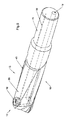
- a drill 10 is shown as an example of a cutting tool, without thereby limiting the teaching according to the invention. Rather, this is applicable to all cutting tools, such. B. also on milling tools or reamers.
- the tool is cooled by means of cooling fluid guided in a closed circuit, which is a liquefied gas, in particular liquefied CO2, although other liquefied gases come into consideration, which have the property that feeding to the tool at a temperature of in particular less than 50 ° C is possible to then at least partially evaporate in an expansion space.
- a liquefied gas in particular liquefied CO2
- other liquefied gases come into consideration, which have the property that feeding to the tool at a temperature of in particular less than 50 ° C is possible to then at least partially evaporate in an expansion space.
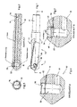
- FIG. 6 A correspondingly closed circuit is the Fig. 6 refer to.
- this tool 10 with this receiving chuck 14 is shown purely in principle.
- a doctorzu glasskanal 16 and a coolant return passage 18, which via terminals 20, 22 - deviating from the drawing - may also be formed as rotary passages, pass into a line 24, in which a compressor 26 and an expansion valve 28th are arranged.
- the flow direction of the coolant is symbolized by the arrows 30.
- the cross-section of the feed channel 16 is considerably smaller than that of the return channel 18.
- the feed channel 16 may, for. Example, a diameter between 0.6 mm and 1 mm, preferably in the range of 0.8 mm and the return channel has a diameter of 3 mm to 6 mm, in particular in the range of 4 mm, to name only by way of example numbers.
- the tool 10 has a tool body 11 with cutting. This area is referred to as the chip area 13, which extends to the front area 12 of the tool body 11, as illustrated by the drawing. Opposite, the tool body 11 has a shaft 15 in order to install the tool in a machine can.
- the channels 16, 18 are connected via a bore 32 which extends over at least one section of an expansion space and runs transversely to the longitudinal axis 34 of the tool 10 and which can be closed by a closure element such as screw 36.
- the bore 32 is in accordance with the graphic representation of an open space 38 of a cutting edge 40 of the tool 10 from.
- the feed channel 16 opens with its opening 42 in the bore 32.
- This - if necessary, including the return channel 18 - is dimensioned such that the inflowing liquid gas can expand in an amount that at least a partial evaporation is made possible.
- the tool 10 heat can be withdrawn to the extent necessary to achieve the desired cooling, which ensures that the tool 10 remains dimensionally stable and the required service life can be achieved.
- the expansion chamber can extend from the bore 32, starting in this one, so that sufficient volume is available to enable the sublimation of the cooling fluid.
- the bore 32 and the return channel 18 should be designed in terms of volume such that the coolant supplied to the bore 32 can expand at least 20 times, preferably 30- to 50-fold.
- the coolant supply channel 16 is adjustable in cross-section. This results in the possibility to adjust the amount of the coolant to be supplied to the bore 32 and thus the expansion space such that sufficient volume for evaporation of the gas is available.
- the opening 42 of the feed channel 16 is adjusted in the cross section by means of the screw 36 formed as a closure element of the bore 32.
- the screw 36 on the inside a trained as a cone portion 44 which bears sealingly against a conical seat 46.
- the conical seat 46 is penetrated by the coolant supply line 16, ie, the opening 42 extends in the conical seat 46.
- the opening 42 is more or less closed and thus changes the amount of the expansion space to be supplied to the coolant.
Landscapes
- Engineering & Computer Science (AREA)
- Mechanical Engineering (AREA)
- Physics & Mathematics (AREA)
- Fluid Mechanics (AREA)
- Drilling Tools (AREA)
- Drilling And Boring (AREA)
Applications Claiming Priority (1)
| Application Number | Priority Date | Filing Date | Title |
|---|---|---|---|
| DE201310111741 DE102013111741A1 (de) | 2013-10-24 | 2013-10-24 | Zerspanungswerkzeug und Verfahren zum Kühlen eines solchen |
Publications (1)
| Publication Number | Publication Date |
|---|---|
| EP2865472A1 true EP2865472A1 (fr) | 2015-04-29 |
Family
ID=51795528
Family Applications (1)
| Application Number | Title | Priority Date | Filing Date |
|---|---|---|---|
| EP20140190354 Withdrawn EP2865472A1 (fr) | 2013-10-24 | 2014-10-24 | Outil d'enlèvement de copeaux et son procédé de refroidissement |
Country Status (2)
| Country | Link |
|---|---|
| EP (1) | EP2865472A1 (fr) |
| DE (1) | DE102013111741A1 (fr) |
Cited By (10)
| Publication number | Priority date | Publication date | Assignee | Title |
|---|---|---|---|---|
| CN106825695A (zh) * | 2017-03-12 | 2017-06-13 | 长葛市宏锦成电动科技有限公司 | 一种多功能钻头 |
| CN106825694A (zh) * | 2017-03-12 | 2017-06-13 | 长葛市宏锦成电动科技有限公司 | 一种降温钻头 |
| CN106862620A (zh) * | 2017-03-12 | 2017-06-20 | 长葛市宏锦成电动科技有限公司 | 一种新型降温钻头 |
| CN106956025A (zh) * | 2017-03-12 | 2017-07-18 | 长葛市宏锦成电动科技有限公司 | 一种具有降温功能的钻头 |
| US10052694B2 (en) | 2016-05-04 | 2018-08-21 | Kennametal Inc. | Apparatus and method for cooling a cutting tool using super critical carbon dioxide |
| CN108577928A (zh) * | 2018-05-22 | 2018-09-28 | 浙江工业大学 | 一种用于钻骨的低温生理盐水冷却回流装置 |
| EP3587031A1 (fr) * | 2018-06-28 | 2020-01-01 | United Technologies Corporation | Système de refroidissement pour outils de coupe rotatifs |
| CN113427053A (zh) * | 2021-06-01 | 2021-09-24 | 东台升华工具有限公司 | 一种钻头自冷却的钻铣加工系统 |
| CN113894612A (zh) * | 2021-10-11 | 2022-01-07 | 四川明日宇航工业有限责任公司 | 结构件加工冷却系统、方法、铣刀、钻头和车刀 |
| CN115780843A (zh) * | 2022-11-29 | 2023-03-14 | 宁波三韩合金材料有限公司 | 一种万能刀盘 |
Families Citing this family (2)
| Publication number | Priority date | Publication date | Assignee | Title |
|---|---|---|---|---|
| DE102016223459A1 (de) * | 2016-11-25 | 2018-05-30 | Schaeffler Technologies AG & Co. KG | Werkzeuganordnung mit Schneidkörper, Verfahren zum Kühlen des Schneidkörpers sowie Verwendung des Schneidkörpers |
| DE102021132676A1 (de) | 2021-12-10 | 2023-06-15 | Horn Hartstoffe Gmbh | Verfahren und Vorrichtung zur Herstellung von Hartmetallpresslingen |
Citations (11)
| Publication number | Priority date | Publication date | Assignee | Title |
|---|---|---|---|---|
| SU727329A1 (ru) * | 1978-10-03 | 1980-04-15 | Предприятие П/Я Г-4585 | Резец с внутренним охлаждением |
| JPS58160001A (ja) * | 1982-03-19 | 1983-09-22 | Hitachi Ltd | 高速加工用バイト |
| EP0186067A2 (fr) * | 1984-12-14 | 1986-07-02 | Továrny strojirenské techniky, koncern | Outil d'usinage à enlèvement de copeaux |
| WO1995029030A1 (fr) | 1994-04-27 | 1995-11-02 | Kennametal Hertel Ag Werkzeuge + Hartstoffe | Outil concentrique, notamment foret |
| DE19730539C1 (de) | 1997-07-16 | 1999-04-08 | Fraunhofer Ges Forschung | Drehmeißel |
| DE19958536C2 (de) | 1999-12-04 | 2002-08-14 | Bosch Gmbh Robert | Werkzeug für eine Werkzeugmaschine |
| EP1023961B1 (fr) | 1999-01-26 | 2003-06-11 | Jakob Lach GmbH & Co. KG | Outil de coupe |
| DE102004032093A1 (de) * | 2004-07-01 | 2006-01-26 | Concept Laser Gmbh | Durch einen selektiven Lasersintervorgang (SLS) hergestelltes Bauteil |
| DE102009030587B3 (de) | 2009-06-26 | 2010-11-04 | Jakob Lach Gmbh & Co. Kg | Zerspanungsweerkzeug, insbesondere Fräs- oder Bohrwerkzeug |
| DE202013101070U1 (de) * | 2013-03-12 | 2013-03-18 | Karl Keppler Maschinenbau Gmbh | Werkzeug für eine Werkzeugmaschine |
| EP2607001A1 (fr) | 2011-12-22 | 2013-06-26 | Technische Universität Darmstadt | Refroidissement d'outils d'usinage |
-
2013
- 2013-10-24 DE DE201310111741 patent/DE102013111741A1/de not_active Withdrawn
-
2014
- 2014-10-24 EP EP20140190354 patent/EP2865472A1/fr not_active Withdrawn
Patent Citations (11)
| Publication number | Priority date | Publication date | Assignee | Title |
|---|---|---|---|---|
| SU727329A1 (ru) * | 1978-10-03 | 1980-04-15 | Предприятие П/Я Г-4585 | Резец с внутренним охлаждением |
| JPS58160001A (ja) * | 1982-03-19 | 1983-09-22 | Hitachi Ltd | 高速加工用バイト |
| EP0186067A2 (fr) * | 1984-12-14 | 1986-07-02 | Továrny strojirenské techniky, koncern | Outil d'usinage à enlèvement de copeaux |
| WO1995029030A1 (fr) | 1994-04-27 | 1995-11-02 | Kennametal Hertel Ag Werkzeuge + Hartstoffe | Outil concentrique, notamment foret |
| DE19730539C1 (de) | 1997-07-16 | 1999-04-08 | Fraunhofer Ges Forschung | Drehmeißel |
| EP1023961B1 (fr) | 1999-01-26 | 2003-06-11 | Jakob Lach GmbH & Co. KG | Outil de coupe |
| DE19958536C2 (de) | 1999-12-04 | 2002-08-14 | Bosch Gmbh Robert | Werkzeug für eine Werkzeugmaschine |
| DE102004032093A1 (de) * | 2004-07-01 | 2006-01-26 | Concept Laser Gmbh | Durch einen selektiven Lasersintervorgang (SLS) hergestelltes Bauteil |
| DE102009030587B3 (de) | 2009-06-26 | 2010-11-04 | Jakob Lach Gmbh & Co. Kg | Zerspanungsweerkzeug, insbesondere Fräs- oder Bohrwerkzeug |
| EP2607001A1 (fr) | 2011-12-22 | 2013-06-26 | Technische Universität Darmstadt | Refroidissement d'outils d'usinage |
| DE202013101070U1 (de) * | 2013-03-12 | 2013-03-18 | Karl Keppler Maschinenbau Gmbh | Werkzeug für eine Werkzeugmaschine |
Cited By (12)
| Publication number | Priority date | Publication date | Assignee | Title |
|---|---|---|---|---|
| US10052694B2 (en) | 2016-05-04 | 2018-08-21 | Kennametal Inc. | Apparatus and method for cooling a cutting tool using super critical carbon dioxide |
| CN106825695A (zh) * | 2017-03-12 | 2017-06-13 | 长葛市宏锦成电动科技有限公司 | 一种多功能钻头 |
| CN106825694A (zh) * | 2017-03-12 | 2017-06-13 | 长葛市宏锦成电动科技有限公司 | 一种降温钻头 |
| CN106862620A (zh) * | 2017-03-12 | 2017-06-20 | 长葛市宏锦成电动科技有限公司 | 一种新型降温钻头 |
| CN106956025A (zh) * | 2017-03-12 | 2017-07-18 | 长葛市宏锦成电动科技有限公司 | 一种具有降温功能的钻头 |
| CN108577928A (zh) * | 2018-05-22 | 2018-09-28 | 浙江工业大学 | 一种用于钻骨的低温生理盐水冷却回流装置 |
| EP3587031A1 (fr) * | 2018-06-28 | 2020-01-01 | United Technologies Corporation | Système de refroidissement pour outils de coupe rotatifs |
| US10786853B2 (en) | 2018-06-28 | 2020-09-29 | United Technologies Corporation | Cooling system for rotating cutting tools |
| CN113427053A (zh) * | 2021-06-01 | 2021-09-24 | 东台升华工具有限公司 | 一种钻头自冷却的钻铣加工系统 |
| CN113894612A (zh) * | 2021-10-11 | 2022-01-07 | 四川明日宇航工业有限责任公司 | 结构件加工冷却系统、方法、铣刀、钻头和车刀 |
| CN115780843A (zh) * | 2022-11-29 | 2023-03-14 | 宁波三韩合金材料有限公司 | 一种万能刀盘 |
| CN115780843B (zh) * | 2022-11-29 | 2024-04-26 | 宁波三韩合金材料有限公司 | 一种万能刀盘 |
Also Published As
| Publication number | Publication date |
|---|---|
| DE102013111741A1 (de) | 2015-04-30 |
Similar Documents
| Publication | Publication Date | Title |
|---|---|---|
| EP2865472A1 (fr) | Outil d'enlèvement de copeaux et son procédé de refroidissement | |
| DE102014119295B4 (de) | Werkzeughalter für einen Schneideinsatz sowie Verfahren zur Herstellung des Werkzeughalters | |
| EP2832493B1 (fr) | Dispositif de traitement et procédé de traitement de pièces à usiner | |
| DE102017126931B4 (de) | Werkzeuganordnung mit Schneidkörper sowie Verfahren zum Kühlen des Schneidkörpers | |
| EP1420918B1 (fr) | Procede et outil d'usinage de pieces avec refroidissement | |
| DE102012001796B4 (de) | Segmentierter Orbitalbohrer | |
| EP2837448B1 (fr) | Porte-outil | |
| EP2688725B1 (fr) | Vis pour utilisation en pyrolyse | |
| DE102013003291A1 (de) | Gewindeformwerkzeug | |
| DE102019102726A1 (de) | Bohrwerkzeug und Verfahren zur Erzeugung einer Bohrung | |
| DE102009041812B4 (de) | Fräser mit einer schaftartigen Grundform | |
| DE102014108989A1 (de) | Verzweiger für einen Kältemittelstrom eines Kältemittelkreislaufs | |
| DE102019103446A1 (de) | Schneideinsatz mit internen Kühlmitteldurchgängen | |
| WO2009037223A1 (fr) | Tige d'outil en matériau fritté seulement partiellement affûtée | |
| EP2894007B1 (fr) | Procédé et dispositif de mélange pour la production d'une substance de refroidissement et/ou de lubrification multiphases pour un refroidissement et/ou une lubrification d'un dispositif d'usinage | |
| DE10144514A1 (de) | Schneidwerkzeug | |
| DE202006011535U1 (de) | Schneidplatte | |
| DE10317567A1 (de) | Hochgeschwindigkeits-Zerspanungsverfahren | |
| WO2019173855A1 (fr) | Procédé de fabrication d'un corps composite fritté | |
| EP2164660B1 (fr) | Porte-outil avec plaquette de coupe | |
| DE3631763C2 (fr) | ||
| WO2013010669A1 (fr) | Outil d'usinage muni d'un dispositif de refroidissement | |
| DE102017113261A1 (de) | Werkzeugschaft und Werkzeugmodul mit integrierter Kaltgaserzeugung | |
| DE10351327A1 (de) | Bohrwerkzeug | |
| DE202012102651U1 (de) | Blasform für die Herstellung von Behältern mit Mündung |
Legal Events
| Date | Code | Title | Description |
|---|---|---|---|
| PUAI | Public reference made under article 153(3) epc to a published international application that has entered the european phase |
Free format text: ORIGINAL CODE: 0009012 |
|
| 17P | Request for examination filed |
Effective date: 20141024 |
|
| AK | Designated contracting states |
Kind code of ref document: A1 Designated state(s): AL AT BE BG CH CY CZ DE DK EE ES FI FR GB GR HR HU IE IS IT LI LT LU LV MC MK MT NL NO PL PT RO RS SE SI SK SM TR |
|
| AX | Request for extension of the european patent |
Extension state: BA ME |
|
| STAA | Information on the status of an ep patent application or granted ep patent |
Free format text: STATUS: THE APPLICATION IS DEEMED TO BE WITHDRAWN |
|
| 18D | Application deemed to be withdrawn |
Effective date: 20151030 |