EP2865595A1 - Système de commande de frein de rotor - Google Patents
Système de commande de frein de rotor Download PDFInfo
- Publication number
- EP2865595A1 EP2865595A1 EP20140150510 EP14150510A EP2865595A1 EP 2865595 A1 EP2865595 A1 EP 2865595A1 EP 20140150510 EP20140150510 EP 20140150510 EP 14150510 A EP14150510 A EP 14150510A EP 2865595 A1 EP2865595 A1 EP 2865595A1
- Authority
- EP
- European Patent Office
- Prior art keywords
- rotor brake
- rotor
- brake
- caliper
- amount
- Prior art date
- Legal status (The legal status is an assumption and is not a legal conclusion. Google has not performed a legal analysis and makes no representation as to the accuracy of the status listed.)
- Granted
Links
Images


Classifications
-
- F—MECHANICAL ENGINEERING; LIGHTING; HEATING; WEAPONS; BLASTING
- F16—ENGINEERING ELEMENTS AND UNITS; GENERAL MEASURES FOR PRODUCING AND MAINTAINING EFFECTIVE FUNCTIONING OF MACHINES OR INSTALLATIONS; THERMAL INSULATION IN GENERAL
- F16D—COUPLINGS FOR TRANSMITTING ROTATION; CLUTCHES; BRAKES
- F16D66/00—Arrangements for monitoring working conditions, e.g. wear, temperature
-
- B—PERFORMING OPERATIONS; TRANSPORTING
- B64—AIRCRAFT; AVIATION; COSMONAUTICS
- B64C—AEROPLANES; HELICOPTERS
- B64C27/00—Rotorcraft; Rotors peculiar thereto
- B64C27/04—Helicopters
- B64C27/12—Rotor drives
-
- F—MECHANICAL ENGINEERING; LIGHTING; HEATING; WEAPONS; BLASTING
- F16—ENGINEERING ELEMENTS AND UNITS; GENERAL MEASURES FOR PRODUCING AND MAINTAINING EFFECTIVE FUNCTIONING OF MACHINES OR INSTALLATIONS; THERMAL INSULATION IN GENERAL
- F16D—COUPLINGS FOR TRANSMITTING ROTATION; CLUTCHES; BRAKES
- F16D66/00—Arrangements for monitoring working conditions, e.g. wear, temperature
- F16D2066/001—Temperature
-
- F—MECHANICAL ENGINEERING; LIGHTING; HEATING; WEAPONS; BLASTING
- F16—ENGINEERING ELEMENTS AND UNITS; GENERAL MEASURES FOR PRODUCING AND MAINTAINING EFFECTIVE FUNCTIONING OF MACHINES OR INSTALLATIONS; THERMAL INSULATION IN GENERAL
- F16D—COUPLINGS FOR TRANSMITTING ROTATION; CLUTCHES; BRAKES
- F16D66/00—Arrangements for monitoring working conditions, e.g. wear, temperature
- F16D2066/003—Position, angle or speed
Definitions
- This invention relates generally to rotorcraft brakes, and more particularly, to a rotor brake control system.
- a rotorcraft may include one or more rotor systems.
- a rotorcraft rotor system is a main rotor system.
- a main rotor system may generate aerodynamic lift to support the weight of the rotorcraft in flight and thrust to counteract aerodynamic drag and move the rotorcraft in forward flight.
- Another example of a rotorcraft rotor system is a tail rotor system.
- a tail rotor system may generate thrust in the same direction as the main rotor system's rotation to counter the torque effect created by the main rotor system.
- a technical advantage of one embodiment may include the capability to improve rotorcraft braking performance.
- a technical advantage of one embodiment may also include the capability to improve cool the braking disk of a rotorcraft braking system.
- a technical advantage of one embodiment may also include the capability to improve rotorcraft braking performance by replacing the solid braking disk with a braking disk having a built-in impeller for cooling the braking disk.
- a technical advantage of one embodiment may also include the capability to improve rotorcraft braking performance by providing a rotor brake control system that manages rotor brake operation as a function of temperature.
- FIGURE 1A shows a rotorcraft 100 according to one example embodiment.
- Rotorcraft 100 features a rotor system 110, blades 120, a fuselage 130, a landing gear 140, and an empennage 150.
- Rotor system 110 may rotate blades 120.
- Rotor system 110 may include a control system for selectively controlling the pitch of each blade 120 in order to selectively control direction, thrust, and lift of rotorcraft 100.
- Fuselage 130 represents the body of rotorcraft 100 and may be coupled to rotor system 110 such that rotor system 110 and blades 120 may move fuselage 130 through the air.
- Landing gear 140 supports rotorcraft 100 when rotorcraft 100 is landing and/or when rotorcraft 100 is at rest on the ground.
- Empennage 150 represents the tail section of the aircraft and features components of a rotor system 110 and blades 120'. Blades 120' may provide thrust in the same direction as the rotation of blades 120 so as to counter the torque effect created by rotor system 110 and blades 120.
- Teachings of certain embodiments relating to rotor systems described herein may apply to rotor system 110 and/or other rotor systems, such as other tilt rotor and helicopter rotor systems. It should also be appreciated that teachings from rotorcraft 100 may apply to aircraft other than rotorcraft, such as airplanes and unmanned aircraft, to name a few examples.
- rotor system 110 may rotate blades 120, the drive shaft, and other components at a very high speed.
- a particular rotorcraft 100 may operate rotor system 110 at 8100 revolutions per minute.
- the operator of rotorcraft 100 may wish to slow the rotation of blades 120.
- the operator may wish to slow/stop the rotation of blades 120 after landing rotorcraft 100.
- some rotorcraft may be equipped with a rotor braking system.
- An example rotor braking system may include a solid braking disk in mechanical communication with rotor system 110 and a combination of calipers and brake pads operable to slow rotation of the solid braking disk, thereby slowing rotation of rotor system 110.
- the solid braking disk slows rotation of rotor system 110 by converting angular momentum into heat. Overheating the solid braking disk, however, may cause a variety of problems, such as permanent warping of the disk, vibrations, and shearing of disk mounting bolts. In addition, a warped brake disk must be replaced, adding considerable expense and delays to normal rotorcraft operation.
- the solid breaking disk may release some heat into the surrounding environment, the solid braking disk may not be able to release heat quickly enough for efficient braking.
- a rotorcraft 100 equipped with a 9.5 inch diameter solid braking disk may be limited to only applying the rotor brake once per hour and/or may be limited to only applying the rotor brake once the rotation speed of blades 120 has slowed to forty percent of normal operating speed.
- increasing the size of the solid braking disk may improve thermal release during operation but may also cause other design issues within a rotorcraft 100.
- teachings of certain embodiments recognize the capability to improve rotorcraft braking performance by cooling the braking disk.
- teachings of certain embodiments recognize the capability to improve rotorcraft braking performance by replacing the solid braking disk with a braking disk having a built-in impeller for cooling the braking disk.
- teachings of certain embodiments recognize the capability to improve rotorcraft braking performance by providing a rotor brake control system that manages rotor brake operation as a function of temperature.
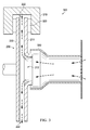
- FIGURE 2 shows a rotor brake 200 according to one example embodiment.
- rotor brake 200 features braking surfaces 210 and 220 and an impeller 230.
- braking surface 210 has an opening 212 therethrough.
- opening 212 may operate as an inlet, allowing air to enter into impeller 230.
- Braking surface 220 is adjacent to braking surface 210 and is separated from braking surface 210 by gaps 222.
- Impeller 230 is disposed between and fixably coupled to braking surfaces 210 and 220. In operation, according to some embodiments, rotation of rotor brake 200 causes braking surface 210, braking surface 220, and impeller 230 to rotate. Rotation of impeller 230 causes impeller 230 to pull fluid through opening 212 (the inlet) and expel the fluid through gaps 222 (the outlets).
- braking surface 210, braking surface 220, and impeller 230 may, in combination, represent a centrifugal pump.
- a centrifugal pump is a device that transports fluids by the conversion of rotational kinetic energy to the hydrodynamic energy of the fluid flow.
- impeller 230 may represent a closed concept, end suction, impeller.
- impeller 230 may represent a closed concept impeller because it is bounded by braking surfaces 210 and 220.
- impeller 230 may represent an end suction impeller because of how it pulls fluid through opening 212.
- the axis of rotation of impeller 230 passes through opening 212, which may allow impeller 230 to receive fluid through the center of the impeller and expel the fluid out the outer circumference of the impeller.
- FIGURE 3 shows a rotor brake system 300 according to one example embodiment.
- rotor brake system 300 features the rotor brake 200 of FIGURE 2 , calipers 310, brake pads 320, and ducts 330.
- the impeller 230 of rotor brake 200 has been removed from FIGURE 3 for clarity purposes.
- rotor brake system 300 may slow rotation of rotor brake 200 by the friction caused by pushing brake pads 320 against braking surfaces 210 and 220 using calipers 320.
- rotor brake 200 is in mechanical communication with the drive shaft of rotor system 110 such that rotor brake 200 and the drive shaft rotate at approximately the same speed. Accordingly, slowing rotation of rotor brake 200 also slows rotation of the drive shaft, which then slows rotation of blades 120.
- impeller 230 may cool rotor brake 200 by pumping fluid past braking surfaces 210 and 220, thus allowing braking surfaces 210 and 220 to transfer heat to the flow of fluid.
- teachings of certain embodiments recognize that providing impeller 230 may allow rotor brake 200 to cool much more quickly than a solid rotor disk.
- the fluid pumped through rotor brake 200 may also be used to cool other components within rotorcraft 100.
- the fluid pumped through rotor brake 200 may also cool components near rotor brake 200, such as the transmission and generator.
- teachings of certain embodiments recognize that a variety of fluids may be used to cool rotor brake 200 and/or surrounding components.
- the fluid is air.
- teachings of certain embodiments recognize that air may remove large amounts of heat from rotor brake 200 when rotor brake 200 is rotating at higher speeds.
- ducts 330 may improve cooling efficiency by providing air from outside rotorcraft 100.
- teachings of certain embodiments recognize that outside air may be significantly cooler than air found within the rotorcraft body, where air temperatures can be in excess of 250 degrees Fahrenheit.
- Embodiments of rotor brake 200 and rotor brake system 300 may include more, fewer, or different components.
- rotor brake system 300 may include multiple rotor brakes 200.
- rotor brake system 300 may include two rotor brakes 200 rotating in opposite directions.
- a rotor brake may generate a considerable amount of heat, and excess heat may limit rotor brake performance or cause rotor brake failure.
- teachings of certain embodiments recognize that devices such as rotor brake 200 may improve rotor brake performance by removing heat from the rotor brake.
- teachings of certain embodiments recognize the capability to improve rotor brake performance by controlling operation of a rotor brake as a function of temperature.
- FIGURE 4 shows a rotor brake control system 400 according to one example embodiment.
- system 400 features temperature sensors 410, a yaw rate sensor 430, a rotor brake control unit 440, and a pressure controller 450, that may be implemented at least partially by one or more computer systems 10. All, some, or none of the components of system 400 may be located on or near rotorcraft 100 (or another aircraft).
- Users 5 may access system 400 through computer systems 10.
- users 5 may access rotor brake control unit 440, which may be at least partially associated with a computer system 10.
- Users 5 may include any individual, group of individuals, entity, machine, and/or mechanism that interacts with computer systems 10. Examples of users 5 include, but are not limited to, a pilot, service person, engineer, technician, contractor, agent, and/or employee.
- Users 5 may be associated with an organization.
- An organization may include any social arrangement that pursues collective goals.
- An organization is a business.
- a business is an organization designed to provide goods or services, or both, to consumers, governmental entities, and/or other businesses.
- Computer system 10 may include processors 12, input/output devices 14, communications links 16, and memory 18. In other embodiments, computer system 10 may include more, less, or other components. Computer system 10 may be operable to perform one or more operations of various embodiments. Although the embodiment shown provides one example of computer system 10 that may be used with other embodiments, such other embodiments may utilize computers other than computer system 10. Additionally, embodiments may also employ multiple computer systems 10 or other computers networked together in one or more public and/or private computer networks, such as one or more networks 30.
- Processors 12 represent devices operable to execute logic contained within a medium. Examples of processor 12 include one or more microprocessors, one or more applications, and/or other logic. Computer system 10 may include one or multiple processors 12.
- Input/output devices 14 may include any device or interface operable to enable communication between computer system 10 and external components, including communication with a user or another system.
- Example input/output devices 14 may include, but are not limited to, a mouse, keyboard, display, and printer.
- Network interfaces 16 are operable to facilitate communication between computer system 10 and another element of a network, such as other computer systems 10.
- Network interfaces 16 may connect to any number and combination of wireline and/or wireless networks suitable for data transmission, including transmission of communications.
- Network interfaces 16 may, for example, communicate audio and/or video signals, messages, internet protocol packets, frame relay frames, asynchronous transfer mode cells, and/or other suitable data between network addresses.
- Network interfaces 16 connect to a computer network or a variety of other communicative platforms including, but not limited to, a public switched telephone network (PSTN); a public or private data network; one or more intranets; a local area network (LAN); a metropolitan area network (MAN); a wide area network (WAN); a wireline or wireless network; a local, regional, or global communication network; an optical network; a satellite network; a cellular network; an enterprise intranet; all or a portion of the Internet; other suitable network interfaces; or any combination of the preceding.
- PSTN public switched telephone network
- LAN local area network
- MAN metropolitan area network
- WAN wide area network
- wireline or wireless network a local, regional, or global communication network
- an optical network a satellite network
- a cellular network an enterprise intranet
- all or a portion of the Internet other suitable network interfaces; or any combination of the preceding.
- Memory 18 represents any suitable storage mechanism and may store any data for use by computer system 10.
- Memory 18 may comprise one or more tangible, computer-readable, and/or computer-executable storage medium.
- Examples of memory 18 include computer memory (for example, Random Access Memory (RAM) or Read Only Memory (ROM)), mass storage media (for example, a hard disk), removable storage media (for example, a Compact Disk (CD) or a Digital Video Disk (DVD)), database and/or network storage (for example, a server), and/or other computer-readable medium.
- memory 18 stores logic 20.
- Logic 20 facilitates operation of computer system 10.
- Logic 20 may include hardware, software, and/or other logic.
- Logic 20 may be encoded in one or more tangible, non-transitory media and may perform operations when executed by a computer.
- Logic 20 may include a computer program, software, computer executable instructions, and/or instructions capable of being executed by computer system 10.
- Example logic 20 may include any of the well-known OS2, UNIX, Mac-OS, Linux, and Windows Operating Systems or other operating systems.
- the operations of the embodiments may be performed by one or more computer readable media storing, embodied with, and/or encoded with a computer program and/or having a stored and/or an encoded computer program.
- Logic 20 may also be embedded within any other suitable medium without departing from the scope of the invention.
- Network 30 may represent any number and combination of wireline and/or wireless networks suitable for data transmission.
- Network 30 may, for example, communicate internet protocol packets, frame relay frames, asynchronous transfer mode cells, and/or other suitable data between network addresses.
- Network 30 may include a public or private data network; one or more intranets; a local area network (LAN); a metropolitan area network (MAN); a wide area network (WAN); a wireline or wireless network; a local, regional, or global communication network; an optical network; a satellite network; a cellular network; an enterprise intranet; all or a portion of the Internet; other suitable communication links; or any combination of the preceding.
- teachings of certain embodiments recognize that more or fewer networks may be used and that not all elements may communicate via a network.
- teachings of certain embodiments also recognize that communications over a network is one example of a mechanism for communicating between parties, and any suitable mechanism may be used.
- Temperature sensors 410 may measure (or receive measurements representative of) an operating temperature of a rotor brake (such as rotor brake 200).
- the operating temperature of a rotor brake may represent any temperature associated with the operation of the rotor brake, such as surface temperature of the rotor brake measured during operation of the rotor brake.
- temperature sensors 410 may represent infrared temperature sensors configured to measure the surface temperature of a rotor brake.
- rotor brake system 300 may include multiple rotor brakes 200, and rotor brake control system 400 may include temperature sensors 410 associated with each rotor brake 200.
- Yaw rate sensor 430 may detect and/or measure yaw movement of an aircraft (such as rotorcraft 100).
- An aircraft such as rotorcraft 100 may be subject to yaw movement, for example, if applying pressure to a rotor brake while the aircraft is parked on a slippery surface.
- Rotor brake control unit 440 may receive measurements from temperature sensors 410 and yaw rate sensor 430, and send instructions to pressure controller 450 based on the received measurements.
- Pressure controller 450 may instruct calipers 310 on how to applying braking pressure against rotor brake 200 using brake pads 320.
- pressure controller 450 may instruct calipers 310 to increase or decrease braking pressure, which may result in a change in friction and heat generation.
- rotor brake control unit 440 instructs pressure controller 450 to change the amount of friction generated between brake pads 320 and rotor brake 200 based on the operating temperature measured by temperature sensors 410. For example, rotor brake control unit 440 may instruct pressure controller 450 to reduce the amount of friction generated between brake pads 320 and rotor brake 200 if the measured operating temperature exceeds a threshold value. This threshold value may represent, for example, a maximum operating temperature of rotor brake 200. In another example, rotor brake control unit 440 may instruct pressure controller 450 to increase or decrease the amount of friction generated between brake pads 320 and rotor brake 200 such that the measured operating temperature moves towards a preferred value (e.g., 800 degrees Fahrenheit).
- a preferred value e.g. 800 degrees Fahrenheit
- rotor brake control unit 440 may allow rotor brake system 300 to achieve efficient rotor braking by reducing braking force if the measured operating temperature of rotor brake 200 exceeds a preferred value or increasing braking force if the measured operating temperature of rotor brake 200 is less than the preferred value.
- rotor brake control unit 440 instructs pressure controller 450 to change the amount of friction generated between brake pads 320 and rotor brake 200 if yaw movement is detected by yaw rate sensor 430.
- rotor brake control unit 440 may instruct pressure controller 450 to reduce the amount of friction generated between brake pads 320 and rotor brake 200 if the measured yaw movement exceeds a threshold value.
- this threshold value may be set at zero or a value near zero. Teachings of certain embodiments recognize that adjusting braking force based on detection of yaw movement may allow rotor brake control system 400 to prevent a yaw event before the pilot is able to sense and react to yaw.
- rotor brake control system 400 may measure these and other performance factors and increase or decrease rotor braking force based on these measurements.
- rotor brake control system 400 may decrease braking force in response to detected yaw movement even if the measured temperatures and rotor brake speeds are within acceptable operating ranges.
Landscapes
- Engineering & Computer Science (AREA)
- Mechanical Engineering (AREA)
- General Engineering & Computer Science (AREA)
- Aviation & Aerospace Engineering (AREA)
- Braking Arrangements (AREA)
Applications Claiming Priority (1)
| Application Number | Priority Date | Filing Date | Title |
|---|---|---|---|
| US14/060,016 US9267561B2 (en) | 2013-10-22 | 2013-10-22 | Rotor brake control system |
Publications (2)
| Publication Number | Publication Date |
|---|---|
| EP2865595A1 true EP2865595A1 (fr) | 2015-04-29 |
| EP2865595B1 EP2865595B1 (fr) | 2015-09-02 |
Family
ID=49885181
Family Applications (1)
| Application Number | Title | Priority Date | Filing Date |
|---|---|---|---|
| EP14150510.7A Active EP2865595B1 (fr) | 2013-10-22 | 2014-01-08 | Système de commande de frein de rotor |
Country Status (2)
| Country | Link |
|---|---|
| US (1) | US9267561B2 (fr) |
| EP (1) | EP2865595B1 (fr) |
Cited By (3)
| Publication number | Priority date | Publication date | Assignee | Title |
|---|---|---|---|---|
| ITUB20153904A1 (it) * | 2015-09-25 | 2017-03-25 | Levi Dancona Pier Lorenzo | Dispositivo atto a regolare la temperatura dei freni |
| KR20180138420A (ko) * | 2017-06-21 | 2018-12-31 | 주식회사 포스코 | 제동시스템 및 제동방법 |
| EP3650340A1 (fr) * | 2018-11-12 | 2020-05-13 | Ratier-Figeac SAS | Dispositif de gestion de surchauffe de frein de rotor |
Families Citing this family (14)
| Publication number | Priority date | Publication date | Assignee | Title |
|---|---|---|---|---|
| ITTO20130307A1 (it) | 2013-04-17 | 2014-10-18 | Itt Italia Srl | Metodo per realizzare un elemento frenante, in particolare una pastiglia freno, sensorizzato, pastiglia freno sensorizzata, impianto frenante di veicolo e metodo associato |
| US9939035B2 (en) | 2015-05-28 | 2018-04-10 | Itt Italia S.R.L. | Smart braking devices, systems, and methods |
| ITUB20153706A1 (it) * | 2015-09-17 | 2017-03-17 | Itt Italia Srl | Dispositivo frenante per veicolo pesante e metodo di prevenzione del surriscaldamento dei freni in un veicolo pesante |
| ITUB20153709A1 (it) | 2015-09-17 | 2017-03-17 | Itt Italia Srl | Dispositivo di analisi e gestione dei dati generati da un sistema frenante sensorizzato per veicoli |
| ITUA20161336A1 (it) | 2016-03-03 | 2017-09-03 | Itt Italia Srl | Dispositivo e metodo per il miglioramento delle prestazioni di un sistema antibloccaggio e antiscivolamento di un veicolo |
| GB2550364A (en) * | 2016-05-16 | 2017-11-22 | Airbus Operations Ltd | Aircraft brake temperature measurement |
| US10072796B2 (en) | 2016-07-13 | 2018-09-11 | Pratt & Whitney Canada Corp. | Metering of oil flow to engine propeller |
| IT201600077944A1 (it) | 2016-07-25 | 2018-01-25 | Itt Italia Srl | Dispositivo per il rilevamento della coppia residua di frenatura in un veicolo equipaggiato con freni a disco |
| US11186185B2 (en) | 2017-05-31 | 2021-11-30 | Textron Innovations Inc. | Rotor brake effect by using electric distributed anti-torque generators and opposing electric motor thrust to slow a main rotor |
| IT201900015839A1 (it) | 2019-09-06 | 2021-03-06 | Itt Italia Srl | Pastiglia freno per veicoli e suo processo di produzione |
| IT202000013408A1 (it) | 2020-06-05 | 2021-12-05 | Itt Italia Srl | Pastiglia freno intelligente di veicolo e suo metodo di manifattura |
| CN111853100B (zh) * | 2020-07-31 | 2022-03-08 | 日立电梯(广州)自动扶梯有限公司 | 自动扶梯制动系统及控制方法 |
| US20240241003A1 (en) | 2021-05-25 | 2024-07-18 | Itt Italia S.R.L. | A method and a device for estimating residual torque between the braked and braking elements of a vehicle |
| GB2613414A (en) * | 2021-11-30 | 2023-06-07 | Airbus Operations Ltd | Temperature sensing device for aircraft wheel brake |
Citations (4)
| Publication number | Priority date | Publication date | Assignee | Title |
|---|---|---|---|---|
| US6193464B1 (en) * | 1998-12-02 | 2001-02-27 | Mcdonnell Douglas Helicopter Company, | Active brake control for rotor/wing aircraft |
| EP1650431A2 (fr) * | 2004-10-19 | 2006-04-26 | REpower Systems AG | Dispositif destiné à une éolienne |
| DE102006028671A1 (de) * | 2006-06-22 | 2007-12-27 | Siemens Ag | Geregelte Rotorbremse |
| FR2982923A1 (fr) * | 2011-11-21 | 2013-05-24 | Ratier Figeac Soc | Systeme de frein d'arbre rotatif, en particulier pour rotor ou helice d'aeronefs, comportant un actionneur lineaire |
Family Cites Families (5)
| Publication number | Priority date | Publication date | Assignee | Title |
|---|---|---|---|---|
| CH534318A (de) | 1971-06-07 | 1973-02-28 | Saurer Ag Adolph | Vorrichtung zum kraftschlüssigen Verbinden zweier Bauteile |
| US5651430A (en) | 1992-03-31 | 1997-07-29 | Rancourt; Claude | Disc brake assembly |
| IT1293677B1 (it) | 1997-08-01 | 1999-03-08 | Finmeccanica Spa | Freno rotore per un elicottero. |
| DE10343055B4 (de) | 2003-09-16 | 2007-03-29 | Eurocopter Deutschland Gmbh | Rotorbremse |
| FR2886176B1 (fr) * | 2005-05-25 | 2007-07-06 | Eurocopter France | Generateur de vibrations par effet centrifuge a rotors contrarotatifs coaxiaux. |
-
2013
- 2013-10-22 US US14/060,016 patent/US9267561B2/en active Active
-
2014
- 2014-01-08 EP EP14150510.7A patent/EP2865595B1/fr active Active
Patent Citations (4)
| Publication number | Priority date | Publication date | Assignee | Title |
|---|---|---|---|---|
| US6193464B1 (en) * | 1998-12-02 | 2001-02-27 | Mcdonnell Douglas Helicopter Company, | Active brake control for rotor/wing aircraft |
| EP1650431A2 (fr) * | 2004-10-19 | 2006-04-26 | REpower Systems AG | Dispositif destiné à une éolienne |
| DE102006028671A1 (de) * | 2006-06-22 | 2007-12-27 | Siemens Ag | Geregelte Rotorbremse |
| FR2982923A1 (fr) * | 2011-11-21 | 2013-05-24 | Ratier Figeac Soc | Systeme de frein d'arbre rotatif, en particulier pour rotor ou helice d'aeronefs, comportant un actionneur lineaire |
Cited By (3)
| Publication number | Priority date | Publication date | Assignee | Title |
|---|---|---|---|---|
| ITUB20153904A1 (it) * | 2015-09-25 | 2017-03-25 | Levi Dancona Pier Lorenzo | Dispositivo atto a regolare la temperatura dei freni |
| KR20180138420A (ko) * | 2017-06-21 | 2018-12-31 | 주식회사 포스코 | 제동시스템 및 제동방법 |
| EP3650340A1 (fr) * | 2018-11-12 | 2020-05-13 | Ratier-Figeac SAS | Dispositif de gestion de surchauffe de frein de rotor |
Also Published As
| Publication number | Publication date |
|---|---|
| EP2865595B1 (fr) | 2015-09-02 |
| US9267561B2 (en) | 2016-02-23 |
| US20150112515A1 (en) | 2015-04-23 |
Similar Documents
| Publication | Publication Date | Title |
|---|---|---|
| US9267561B2 (en) | Rotor brake control system | |
| US20200140069A1 (en) | Disconnecting a rotor | |
| CN103717493B (zh) | 离心分开离合器 | |
| US9683652B2 (en) | Method for the delivery of lubricant to a rotorcraft gearbox | |
| US8882024B1 (en) | Rotorcraft anti-torque rotor and rudder system | |
| CN110884646B (zh) | 飞行器轮制动器的控制 | |
| EP2818410A1 (fr) | Système de commande anticouple de giravion | |
| US10940945B2 (en) | Rotorcraft anti-torque system | |
| US20180050796A1 (en) | Braking Systems for Rotorcraft | |
| US9604713B2 (en) | Door migration prevention system | |
| US9739326B2 (en) | Rotor brake with integrated impeller | |
| US9735647B2 (en) | Electromagnetic actuator with magnetic torque limiter | |
| CN104875899B (zh) | 一种可停转旋翼飞行器驱动系统以及改变其旋翼系统工作状态的方法 | |
| EP3166846B1 (fr) | Rotation de rotor désolidarisé | |
| KR101502884B1 (ko) | 풍력 터빈의 비상제동 장치 | |
| EP2786936B1 (fr) | Empêcher la condensation sur des lignes de fluide du système de commande environnemental | |
| TR201509203A2 (tr) | Retarder Soğutma Sistemi |
Legal Events
| Date | Code | Title | Description |
|---|---|---|---|
| PUAI | Public reference made under article 153(3) epc to a published international application that has entered the european phase |
Free format text: ORIGINAL CODE: 0009012 |
|
| 17P | Request for examination filed |
Effective date: 20140108 |
|
| AK | Designated contracting states |
Kind code of ref document: A1 Designated state(s): AL AT BE BG CH CY CZ DE DK EE ES FI FR GB GR HR HU IE IS IT LI LT LU LV MC MK MT NL NO PL PT RO RS SE SI SK SM TR |
|
| AX | Request for extension of the european patent |
Extension state: BA ME |
|
| REG | Reference to a national code |
Ref country code: DE Ref legal event code: R079 Ref document number: 602014000165 Country of ref document: DE Free format text: PREVIOUS MAIN CLASS: B64C0027120000 Ipc: B64C0011000000 |
|
| GRAP | Despatch of communication of intention to grant a patent |
Free format text: ORIGINAL CODE: EPIDOSNIGR1 |
|
| RIC1 | Information provided on ipc code assigned before grant |
Ipc: B64C 11/00 20060101AFI20150508BHEP Ipc: F16D 66/00 20060101ALI20150508BHEP Ipc: B64C 27/12 20060101ALI20150508BHEP |
|
| INTG | Intention to grant announced |
Effective date: 20150528 |
|
| GRAS | Grant fee paid |
Free format text: ORIGINAL CODE: EPIDOSNIGR3 |
|
| GRAA | (expected) grant |
Free format text: ORIGINAL CODE: 0009210 |
|
| AK | Designated contracting states |
Kind code of ref document: B1 Designated state(s): AL AT BE BG CH CY CZ DE DK EE ES FI FR GB GR HR HU IE IS IT LI LT LU LV MC MK MT NL NO PL PT RO RS SE SI SK SM TR |
|
| REG | Reference to a national code |
Ref country code: GB Ref legal event code: FG4D |
|
| REG | Reference to a national code |
Ref country code: AT Ref legal event code: REF Ref document number: 746378 Country of ref document: AT Kind code of ref document: T Effective date: 20150915 Ref country code: CH Ref legal event code: EP |
|
| REG | Reference to a national code |
Ref country code: IE Ref legal event code: FG4D |
|
| REG | Reference to a national code |
Ref country code: DE Ref legal event code: R096 Ref document number: 602014000165 Country of ref document: DE |
|
| REG | Reference to a national code |
Ref country code: AT Ref legal event code: MK05 Ref document number: 746378 Country of ref document: AT Kind code of ref document: T Effective date: 20150902 |
|
| REG | Reference to a national code |
Ref country code: FR Ref legal event code: PLFP Year of fee payment: 3 |
|
| PG25 | Lapsed in a contracting state [announced via postgrant information from national office to epo] |
Ref country code: GR Free format text: LAPSE BECAUSE OF FAILURE TO SUBMIT A TRANSLATION OF THE DESCRIPTION OR TO PAY THE FEE WITHIN THE PRESCRIBED TIME-LIMIT Effective date: 20151203 Ref country code: NO Free format text: LAPSE BECAUSE OF FAILURE TO SUBMIT A TRANSLATION OF THE DESCRIPTION OR TO PAY THE FEE WITHIN THE PRESCRIBED TIME-LIMIT Effective date: 20151202 Ref country code: LV Free format text: LAPSE BECAUSE OF FAILURE TO SUBMIT A TRANSLATION OF THE DESCRIPTION OR TO PAY THE FEE WITHIN THE PRESCRIBED TIME-LIMIT Effective date: 20150902 Ref country code: LT Free format text: LAPSE BECAUSE OF FAILURE TO SUBMIT A TRANSLATION OF THE DESCRIPTION OR TO PAY THE FEE WITHIN THE PRESCRIBED TIME-LIMIT Effective date: 20150902 Ref country code: FI Free format text: LAPSE BECAUSE OF FAILURE TO SUBMIT A TRANSLATION OF THE DESCRIPTION OR TO PAY THE FEE WITHIN THE PRESCRIBED TIME-LIMIT Effective date: 20150902 |
|
| REG | Reference to a national code |
Ref country code: LT Ref legal event code: MG4D Ref country code: NL Ref legal event code: MP Effective date: 20150902 |
|
| PG25 | Lapsed in a contracting state [announced via postgrant information from national office to epo] |
Ref country code: AT Free format text: LAPSE BECAUSE OF FAILURE TO SUBMIT A TRANSLATION OF THE DESCRIPTION OR TO PAY THE FEE WITHIN THE PRESCRIBED TIME-LIMIT Effective date: 20150902 Ref country code: PL Free format text: LAPSE BECAUSE OF FAILURE TO SUBMIT A TRANSLATION OF THE DESCRIPTION OR TO PAY THE FEE WITHIN THE PRESCRIBED TIME-LIMIT Effective date: 20150902 Ref country code: ES Free format text: LAPSE BECAUSE OF FAILURE TO SUBMIT A TRANSLATION OF THE DESCRIPTION OR TO PAY THE FEE WITHIN THE PRESCRIBED TIME-LIMIT Effective date: 20150902 Ref country code: RS Free format text: LAPSE BECAUSE OF FAILURE TO SUBMIT A TRANSLATION OF THE DESCRIPTION OR TO PAY THE FEE WITHIN THE PRESCRIBED TIME-LIMIT Effective date: 20150902 Ref country code: SE Free format text: LAPSE BECAUSE OF FAILURE TO SUBMIT A TRANSLATION OF THE DESCRIPTION OR TO PAY THE FEE WITHIN THE PRESCRIBED TIME-LIMIT Effective date: 20150902 |
|
| PG25 | Lapsed in a contracting state [announced via postgrant information from national office to epo] |
Ref country code: CZ Free format text: LAPSE BECAUSE OF FAILURE TO SUBMIT A TRANSLATION OF THE DESCRIPTION OR TO PAY THE FEE WITHIN THE PRESCRIBED TIME-LIMIT Effective date: 20150902 Ref country code: NL Free format text: LAPSE BECAUSE OF FAILURE TO SUBMIT A TRANSLATION OF THE DESCRIPTION OR TO PAY THE FEE WITHIN THE PRESCRIBED TIME-LIMIT Effective date: 20150902 Ref country code: IS Free format text: LAPSE BECAUSE OF FAILURE TO SUBMIT A TRANSLATION OF THE DESCRIPTION OR TO PAY THE FEE WITHIN THE PRESCRIBED TIME-LIMIT Effective date: 20160102 Ref country code: EE Free format text: LAPSE BECAUSE OF FAILURE TO SUBMIT A TRANSLATION OF THE DESCRIPTION OR TO PAY THE FEE WITHIN THE PRESCRIBED TIME-LIMIT Effective date: 20150902 Ref country code: SK Free format text: LAPSE BECAUSE OF FAILURE TO SUBMIT A TRANSLATION OF THE DESCRIPTION OR TO PAY THE FEE WITHIN THE PRESCRIBED TIME-LIMIT Effective date: 20150902 |
|
| PG25 | Lapsed in a contracting state [announced via postgrant information from national office to epo] |
Ref country code: BE Free format text: LAPSE BECAUSE OF NON-PAYMENT OF DUE FEES Effective date: 20160131 Ref country code: PT Free format text: LAPSE BECAUSE OF FAILURE TO SUBMIT A TRANSLATION OF THE DESCRIPTION OR TO PAY THE FEE WITHIN THE PRESCRIBED TIME-LIMIT Effective date: 20160104 Ref country code: RO Free format text: LAPSE BECAUSE OF FAILURE TO SUBMIT A TRANSLATION OF THE DESCRIPTION OR TO PAY THE FEE WITHIN THE PRESCRIBED TIME-LIMIT Effective date: 20150902 |
|
| REG | Reference to a national code |
Ref country code: DE Ref legal event code: R097 Ref document number: 602014000165 Country of ref document: DE |
|
| PLBE | No opposition filed within time limit |
Free format text: ORIGINAL CODE: 0009261 |
|
| STAA | Information on the status of an ep patent application or granted ep patent |
Free format text: STATUS: NO OPPOSITION FILED WITHIN TIME LIMIT |
|
| 26N | No opposition filed |
Effective date: 20160603 |
|
| PG25 | Lapsed in a contracting state [announced via postgrant information from national office to epo] |
Ref country code: SI Free format text: LAPSE BECAUSE OF FAILURE TO SUBMIT A TRANSLATION OF THE DESCRIPTION OR TO PAY THE FEE WITHIN THE PRESCRIBED TIME-LIMIT Effective date: 20150902 Ref country code: DK Free format text: LAPSE BECAUSE OF FAILURE TO SUBMIT A TRANSLATION OF THE DESCRIPTION OR TO PAY THE FEE WITHIN THE PRESCRIBED TIME-LIMIT Effective date: 20150902 Ref country code: LU Free format text: LAPSE BECAUSE OF FAILURE TO SUBMIT A TRANSLATION OF THE DESCRIPTION OR TO PAY THE FEE WITHIN THE PRESCRIBED TIME-LIMIT Effective date: 20160108 |
|
| PG25 | Lapsed in a contracting state [announced via postgrant information from national office to epo] |
Ref country code: MC Free format text: LAPSE BECAUSE OF FAILURE TO SUBMIT A TRANSLATION OF THE DESCRIPTION OR TO PAY THE FEE WITHIN THE PRESCRIBED TIME-LIMIT Effective date: 20150902 |
|
| REG | Reference to a national code |
Ref country code: IE Ref legal event code: MM4A |
|
| PG25 | Lapsed in a contracting state [announced via postgrant information from national office to epo] |
Ref country code: BE Free format text: LAPSE BECAUSE OF FAILURE TO SUBMIT A TRANSLATION OF THE DESCRIPTION OR TO PAY THE FEE WITHIN THE PRESCRIBED TIME-LIMIT Effective date: 20150902 |
|
| REG | Reference to a national code |
Ref country code: FR Ref legal event code: PLFP Year of fee payment: 4 |
|
| PG25 | Lapsed in a contracting state [announced via postgrant information from national office to epo] |
Ref country code: IE Free format text: LAPSE BECAUSE OF NON-PAYMENT OF DUE FEES Effective date: 20160108 |
|
| PG25 | Lapsed in a contracting state [announced via postgrant information from national office to epo] |
Ref country code: MT Free format text: LAPSE BECAUSE OF FAILURE TO SUBMIT A TRANSLATION OF THE DESCRIPTION OR TO PAY THE FEE WITHIN THE PRESCRIBED TIME-LIMIT Effective date: 20150902 |
|
| REG | Reference to a national code |
Ref country code: CH Ref legal event code: PL |
|
| PG25 | Lapsed in a contracting state [announced via postgrant information from national office to epo] |
Ref country code: LI Free format text: LAPSE BECAUSE OF NON-PAYMENT OF DUE FEES Effective date: 20170131 Ref country code: CH Free format text: LAPSE BECAUSE OF NON-PAYMENT OF DUE FEES Effective date: 20170131 |
|
| REG | Reference to a national code |
Ref country code: FR Ref legal event code: PLFP Year of fee payment: 5 |
|
| PG25 | Lapsed in a contracting state [announced via postgrant information from national office to epo] |
Ref country code: HU Free format text: LAPSE BECAUSE OF FAILURE TO SUBMIT A TRANSLATION OF THE DESCRIPTION OR TO PAY THE FEE WITHIN THE PRESCRIBED TIME-LIMIT; INVALID AB INITIO Effective date: 20140108 Ref country code: SM Free format text: LAPSE BECAUSE OF FAILURE TO SUBMIT A TRANSLATION OF THE DESCRIPTION OR TO PAY THE FEE WITHIN THE PRESCRIBED TIME-LIMIT Effective date: 20150902 |
|
| PG25 | Lapsed in a contracting state [announced via postgrant information from national office to epo] |
Ref country code: CY Free format text: LAPSE BECAUSE OF FAILURE TO SUBMIT A TRANSLATION OF THE DESCRIPTION OR TO PAY THE FEE WITHIN THE PRESCRIBED TIME-LIMIT Effective date: 20150902 Ref country code: MK Free format text: LAPSE BECAUSE OF FAILURE TO SUBMIT A TRANSLATION OF THE DESCRIPTION OR TO PAY THE FEE WITHIN THE PRESCRIBED TIME-LIMIT Effective date: 20150902 Ref country code: HR Free format text: LAPSE BECAUSE OF FAILURE TO SUBMIT A TRANSLATION OF THE DESCRIPTION OR TO PAY THE FEE WITHIN THE PRESCRIBED TIME-LIMIT Effective date: 20150902 Ref country code: MT Free format text: LAPSE BECAUSE OF FAILURE TO SUBMIT A TRANSLATION OF THE DESCRIPTION OR TO PAY THE FEE WITHIN THE PRESCRIBED TIME-LIMIT Effective date: 20160131 |
|
| PG25 | Lapsed in a contracting state [announced via postgrant information from national office to epo] |
Ref country code: BG Free format text: LAPSE BECAUSE OF FAILURE TO SUBMIT A TRANSLATION OF THE DESCRIPTION OR TO PAY THE FEE WITHIN THE PRESCRIBED TIME-LIMIT Effective date: 20150902 |
|
| PG25 | Lapsed in a contracting state [announced via postgrant information from national office to epo] |
Ref country code: AL Free format text: LAPSE BECAUSE OF FAILURE TO SUBMIT A TRANSLATION OF THE DESCRIPTION OR TO PAY THE FEE WITHIN THE PRESCRIBED TIME-LIMIT Effective date: 20150902 Ref country code: TR Free format text: LAPSE BECAUSE OF FAILURE TO SUBMIT A TRANSLATION OF THE DESCRIPTION OR TO PAY THE FEE WITHIN THE PRESCRIBED TIME-LIMIT Effective date: 20150902 |
|
| P01 | Opt-out of the competence of the unified patent court (upc) registered |
Effective date: 20230602 |
|
| PGFP | Annual fee paid to national office [announced via postgrant information from national office to epo] |
Ref country code: GB Payment date: 20260127 Year of fee payment: 13 |
|
| PGFP | Annual fee paid to national office [announced via postgrant information from national office to epo] |
Ref country code: DE Payment date: 20260128 Year of fee payment: 13 |
|
| PGFP | Annual fee paid to national office [announced via postgrant information from national office to epo] |
Ref country code: IT Payment date: 20260121 Year of fee payment: 13 |
|
| PGFP | Annual fee paid to national office [announced via postgrant information from national office to epo] |
Ref country code: FR Payment date: 20260126 Year of fee payment: 13 |