EP1650431A2 - Dispositif destiné à une éolienne - Google Patents
Dispositif destiné à une éolienne Download PDFInfo
- Publication number
- EP1650431A2 EP1650431A2 EP05021796A EP05021796A EP1650431A2 EP 1650431 A2 EP1650431 A2 EP 1650431A2 EP 05021796 A EP05021796 A EP 05021796A EP 05021796 A EP05021796 A EP 05021796A EP 1650431 A2 EP1650431 A2 EP 1650431A2
- Authority
- EP
- European Patent Office
- Prior art keywords
- brake
- sensor
- braking device
- braking
- wind
- Prior art date
- Legal status (The legal status is an assumption and is not a legal conclusion. Google has not performed a legal analysis and makes no representation as to the accuracy of the status listed.)
- Granted
Links
Images


Classifications
-
- F—MECHANICAL ENGINEERING; LIGHTING; HEATING; WEAPONS; BLASTING
- F03—MACHINES OR ENGINES FOR LIQUIDS; WIND, SPRING, OR WEIGHT MOTORS; PRODUCING MECHANICAL POWER OR A REACTIVE PROPULSIVE THRUST, NOT OTHERWISE PROVIDED FOR
- F03D—WIND MOTORS
- F03D7/00—Controlling wind motors
- F03D7/02—Controlling wind motors the wind motors having rotation axis substantially parallel to the air flow entering the rotor
- F03D7/0244—Controlling wind motors the wind motors having rotation axis substantially parallel to the air flow entering the rotor for braking
- F03D7/0248—Controlling wind motors the wind motors having rotation axis substantially parallel to the air flow entering the rotor for braking by mechanical means acting on the power train
-
- F—MECHANICAL ENGINEERING; LIGHTING; HEATING; WEAPONS; BLASTING
- F03—MACHINES OR ENGINES FOR LIQUIDS; WIND, SPRING, OR WEIGHT MOTORS; PRODUCING MECHANICAL POWER OR A REACTIVE PROPULSIVE THRUST, NOT OTHERWISE PROVIDED FOR
- F03D—WIND MOTORS
- F03D17/00—Monitoring or testing of wind motors, e.g. diagnostics
-
- F—MECHANICAL ENGINEERING; LIGHTING; HEATING; WEAPONS; BLASTING
- F03—MACHINES OR ENGINES FOR LIQUIDS; WIND, SPRING, OR WEIGHT MOTORS; PRODUCING MECHANICAL POWER OR A REACTIVE PROPULSIVE THRUST, NOT OTHERWISE PROVIDED FOR
- F03D—WIND MOTORS
- F03D80/00—Details, components or accessories not provided for in groups F03D1/00 - F03D17/00
-
- F—MECHANICAL ENGINEERING; LIGHTING; HEATING; WEAPONS; BLASTING
- F16—ENGINEERING ELEMENTS AND UNITS; GENERAL MEASURES FOR PRODUCING AND MAINTAINING EFFECTIVE FUNCTIONING OF MACHINES OR INSTALLATIONS; THERMAL INSULATION IN GENERAL
- F16D—COUPLINGS FOR TRANSMITTING ROTATION; CLUTCHES; BRAKES
- F16D66/00—Arrangements for monitoring working conditions, e.g. wear, temperature
-
- F—MECHANICAL ENGINEERING; LIGHTING; HEATING; WEAPONS; BLASTING
- F05—INDEXING SCHEMES RELATING TO ENGINES OR PUMPS IN VARIOUS SUBCLASSES OF CLASSES F01-F04
- F05B—INDEXING SCHEME RELATING TO WIND, SPRING, WEIGHT, INERTIA OR LIKE MOTORS, TO MACHINES OR ENGINES FOR LIQUIDS COVERED BY SUBCLASSES F03B, F03D AND F03G
- F05B2260/00—Function
- F05B2260/90—Braking
- F05B2260/902—Braking using frictional mechanical forces
-
- F—MECHANICAL ENGINEERING; LIGHTING; HEATING; WEAPONS; BLASTING
- F16—ENGINEERING ELEMENTS AND UNITS; GENERAL MEASURES FOR PRODUCING AND MAINTAINING EFFECTIVE FUNCTIONING OF MACHINES OR INSTALLATIONS; THERMAL INSULATION IN GENERAL
- F16D—COUPLINGS FOR TRANSMITTING ROTATION; CLUTCHES; BRAKES
- F16D55/00—Brakes with substantially-radial braking surfaces pressed together in axial direction, e.g. disc brakes
- F16D2055/0075—Constructional features of axially engaged brakes
- F16D2055/0091—Plural actuators arranged side by side on the same side of the rotor
-
- F—MECHANICAL ENGINEERING; LIGHTING; HEATING; WEAPONS; BLASTING
- F16—ENGINEERING ELEMENTS AND UNITS; GENERAL MEASURES FOR PRODUCING AND MAINTAINING EFFECTIVE FUNCTIONING OF MACHINES OR INSTALLATIONS; THERMAL INSULATION IN GENERAL
- F16D—COUPLINGS FOR TRANSMITTING ROTATION; CLUTCHES; BRAKES
- F16D66/00—Arrangements for monitoring working conditions, e.g. wear, temperature
- F16D2066/001—Temperature
-
- F—MECHANICAL ENGINEERING; LIGHTING; HEATING; WEAPONS; BLASTING
- F16—ENGINEERING ELEMENTS AND UNITS; GENERAL MEASURES FOR PRODUCING AND MAINTAINING EFFECTIVE FUNCTIONING OF MACHINES OR INSTALLATIONS; THERMAL INSULATION IN GENERAL
- F16D—COUPLINGS FOR TRANSMITTING ROTATION; CLUTCHES; BRAKES
- F16D66/00—Arrangements for monitoring working conditions, e.g. wear, temperature
- F16D2066/005—Force, torque, stress or strain
-
- F—MECHANICAL ENGINEERING; LIGHTING; HEATING; WEAPONS; BLASTING
- F16—ENGINEERING ELEMENTS AND UNITS; GENERAL MEASURES FOR PRODUCING AND MAINTAINING EFFECTIVE FUNCTIONING OF MACHINES OR INSTALLATIONS; THERMAL INSULATION IN GENERAL
- F16D—COUPLINGS FOR TRANSMITTING ROTATION; CLUTCHES; BRAKES
- F16D2121/00—Type of actuator operation force
- F16D2121/005—Type of actuator operation force unspecified force for releasing a normally applied brake
-
- F—MECHANICAL ENGINEERING; LIGHTING; HEATING; WEAPONS; BLASTING
- F16—ENGINEERING ELEMENTS AND UNITS; GENERAL MEASURES FOR PRODUCING AND MAINTAINING EFFECTIVE FUNCTIONING OF MACHINES OR INSTALLATIONS; THERMAL INSULATION IN GENERAL
- F16D—COUPLINGS FOR TRANSMITTING ROTATION; CLUTCHES; BRAKES
- F16D2121/00—Type of actuator operation force
- F16D2121/02—Fluid pressure
-
- F—MECHANICAL ENGINEERING; LIGHTING; HEATING; WEAPONS; BLASTING
- F16—ENGINEERING ELEMENTS AND UNITS; GENERAL MEASURES FOR PRODUCING AND MAINTAINING EFFECTIVE FUNCTIONING OF MACHINES OR INSTALLATIONS; THERMAL INSULATION IN GENERAL
- F16D—COUPLINGS FOR TRANSMITTING ROTATION; CLUTCHES; BRAKES
- F16D2121/00—Type of actuator operation force
- F16D2121/18—Electric or magnetic
- F16D2121/24—Electric or magnetic using motors
-
- Y—GENERAL TAGGING OF NEW TECHNOLOGICAL DEVELOPMENTS; GENERAL TAGGING OF CROSS-SECTIONAL TECHNOLOGIES SPANNING OVER SEVERAL SECTIONS OF THE IPC; TECHNICAL SUBJECTS COVERED BY FORMER USPC CROSS-REFERENCE ART COLLECTIONS [XRACs] AND DIGESTS
- Y02—TECHNOLOGIES OR APPLICATIONS FOR MITIGATION OR ADAPTATION AGAINST CLIMATE CHANGE
- Y02E—REDUCTION OF GREENHOUSE GAS [GHG] EMISSIONS, RELATED TO ENERGY GENERATION, TRANSMISSION OR DISTRIBUTION
- Y02E10/00—Energy generation through renewable energy sources
- Y02E10/70—Wind energy
- Y02E10/72—Wind turbines with rotation axis in wind direction
Definitions
- the present invention relates to a device for a wind turbine.
- Wind turbines are designed to take energy from the wind and convert it into electrical energy. Since the wind blows with varying strength from different directions, have wind turbines, in order to influence the energy intake from the wind, among other things, movably arranged components.
- Such a component is z.
- the gondola which is rotatably mounted on the tower of the wind turbine. Due to the rotatable arrangement of the nacelle, the rotor arranged on the nacelle can always be aligned ideally with the wind, so that an optimum energy yield from the wind can be achieved.
- the rotatable arrangement of the nacelle on the tower via a so-called azimuth bearing is usually used as a rolling bearing, z. B. as a four-point ball bearing, running and has an outer and an inner ring, wherein the inner ring of the bearing z. B. is connected to the gondola and the outer ring with the tower.
- a known device has at least one actuator, which is arranged in the region of the azimuth bearing and can be actuated via a control device. It is known to form the actuator hydraulically, for example. Alternatively, it is also known to use an electric drive motor as the actuator.
- the known device may have a directly or indirectly coupled via a gear with the actuator pinion that, for example, is in engagement with a provided on the outer ring of the azimuth bearing outer teeth.
- the actuator is coupled to the nacelle and thus to the inner ring of the bearing. Since the outer ring is firmly connected to the tower, the orientation of the nacelle, by an actuation of the actuator changes.
- the known device is not overcharged, it also has a braking device with which a set orientation of the nacelle can be maintained.
- a braking device can, for. B. serve a holding brake with two brake shoes, which is attached to the nacelle and a stationary between the tower and the outer ring of the bearing brake disc.
- actuation of the brake between the brake shoes arranged brake disc is held by friction, so that the set orientation of the nacelle is fixed.
- the actuation of the holding brake can be done for example via a hydraulic, pneumatic electrical or mechanical drive.
- Wind turbines need to have as little downtime as possible to work efficiently.
- potential hazards such as fire hazards must be minimized.
- the object of the invention is, starting from the cited prior art, to provide a device for a wind turbine, by the particular reliability of the wind turbine is improved.
- the device according to the invention for a wind energy plant has an actuator for aligning at least one movably arranged component of the wind energy plant, which can be actuated via a control device and a braking device for holding a set orientation of the component. Furthermore, the wind turbine according to the invention at least one coupled to the control device, the brake device monitoring sensor, which is designed so that it detects a malfunction of the braking device.
- a non-functioning braking device is a major problem for the reliability of a wind turbine.
- a brake whose brake shoes do not properly close for braking purposes causes the orientation of the nacelle to be held over the actuator.
- a brake device whose brake shoes do not open when needed during the adjustment process to a dangerous increase in temperature in the brake, which in the simplest case to an unnecessary wear the brakes and in the best case can cause a fire in the system.
- the inventive provision of a sensor in the braking device thus offers the advantage that a malfunction of the brake is generally recognizable.
- the sensor can be designed so that it detects malfunctions that do not immediately lead to a shutdown of the system, but their malfunction interfere with the operation of the system only over time or even prevent.
- the component of the wind turbine to be aligned may be the nacelle arranged on the tower.
- the adjusting device of a rotor blade has a braking device for holding a rotor blade alignment.
- the provision according to the invention of a sensor for detecting a defect is also extremely advantageous for adjusting devices for rotor blades.
- Rotors must z. B. for maintenance purposes of a rotor blade so adjustable that the rotor blade to be serviced is aligned horizontally to the tower axis. Smaller rotors can be aligned by hand. However, the orientation by manual operation is no longer possible with very large rotors due to their high mass, so that a device for aligning the rotor must be provided here as well. Accordingly, according to a further advantageous embodiment of the invention, the wind turbine component can also be the rotor of the wind turbine.
- the senor is also coupled to the control device and notifies the control device of a malfunction of the braking device.
- a wired connection z.
- a wired connection e.g., Wifi, etc.
- the coupling of the sensor with the control device offers the advantage that the control device can check based on predetermined parameters, whether due to a reported malfunction, the system is still operable or if the system must be shut down necessary.
- the senor may be designed and arranged such that a temperature change in the region of the braking device can be detected.
- This embodiment of the invention offers the advantage that it is possible via a temperature sensor to decide whether the temperature in the brake has reached an area which is no longer permissible.
- the provision of a temperature sensor is advantageous, for example, in the event that a brake shoe has not opened and, as a result, continues to bear against the brake disk. In such a case, the brake disc would still rotate by means of the actuator, whereby it comes due to the friction between the brake shoe and the brake disc to high temperatures range that are harmful to the operation of the brake.
- the senor for detecting a change in temperature a thermistor, such.
- a thermistor such as a PTC, NTC or a PTxxx.
- the sensor according to the invention can also be designed and arranged according to a further advantageous embodiment of the invention so that wear phenomena of the braking device can be detected.
- Such a sensor may, for. B. in the brake shoes, advantageously be integrated directly in the brake pad. By means of such a sensor can be determined when a brake pad is worn so that it must be replaced.
- the sensor may be designed so that it is detected by the control device, how strong the wear of the brake pads over a certain period, so that z. B. the period is estimated when the brake pad is no longer to use.
- the device therefore has a plurality of actuators, wherein according to a further advantageous embodiment of the invention, the actuators may be mechanically coupled.
- the braking device is fixed, that is, that both brake shoes do not open and the brake disc continue to pinch between them.
- a wind tracking which has only one brake, prevented from moving.
- the drive assembly would be brought by the fixed brake in the short-circuit behavior and the motor protection switch The motors would trigger and prevent the operation of the actuators.
- the braking torque of a brake of a drive would not be enough to bring the drive network in the short-circuit behavior and trigger the motor protection switch. The result is that the wind tracking is driven against the braked system. Because of this, the brake will assume undefined temperatures, which in the worst case can lead to a fire in the system.
- the use of the present invention and its embodiments is particularly advantageous.
- one thermistor can be provided per brake shoe. If the brake does not actually open, the control device registers the rising temperatures. In the control device can be deposited that when exceeding a predetermined temperature, the system is turned off. It would also be conceivable that the sensors are designed and coupled to the actuator, that the actuator is automatically switched off when a limit temperature is exceeded.
- the actuator z. B be a hydraulic motor. According to an advantageous embodiment of the invention, however, at least one actuator, but preferably all actuators, designed as an electric motor.
- the braking device is coupled to the electric motor, according to a further advantageous embodiment of the invention, coupled to the electric motor braking device is designed as Einintenbremse having a fixed brake member and a rotatable brake member, wherein according to a further advantageous embodiment of the invention, the sensor is arranged in the fixed brake part of the single disc brake.
- the braking device may also be designed as a hydraulic braking device. It is also conceivable to provide at least one brake device for some or all actuators or to provide at least one sensor in several or all brake devices.
- a plurality of sensors are provided in the device, they can be connected in series and be connected as a sensor input to the control device. It is also conceivable to connect each sensor to the control device. This would offer the advantage that the control device would recognize in this way on the error message of the sensor, which brake device has a defect.
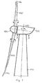
- FIG. 1 shows a wind energy plant with a tower section 100, on which a nacelle 102 is arranged.
- the nacelle 102 is rotatable about the longitudinal axis 103 of the tower.
- a rotor 104 is rotatably mounted.
- On the rotor 104 rotor blades 105 are arranged, which are each designed to be rotatable about their longitudinal axes 106.
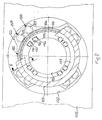
- FIG. 2 shows a section through the tower 100 along the line Y-Y shown in FIG.
- the nacelle 102 has a nacelle opening 120 for connection to the tower 100.
- the cut tower 100 is also partially broken away to better represent the connection between the tower and the nacelle.
- the azimuth bearing consists of an outer ring 126 and an inner ring 127.
- the outer ring 126 is coupled to the tower 100 and also has an outer toothing 124, which in FIG a dash-dotted line is shown.
- the inner ring 127 is connected to a machine carrier 122 arranged in the nacelle 102. To allow access from the tower to the machine frame 122, an access opening 123 is provided in the machine frame.
- each actuator 128 is provided, wherein each two actuators 128 are arranged as a pair and offset from the other Stellantriebsfaren by 90 °.
- the actuators 128 are held by the machine carrier 122.
- each actuator 128 on a pinion 129 which is in engagement with the external teeth of the outer ring 126 of the azimuth bearing 125.
- a control device For holding an orientation represented by the control device, eight brake devices 130 are shown in the illustrated embodiment.
- a braking device is arranged in the region of an actuator 128, wherein the braking devices 130 are each firmly connected to the machine carrier 122.
- Each brake device 130 has two brake shoes, which are not visible in this illustration and enter into an frictional engagement with a brake disc 131 upon actuation of the brake device, which protrudes between the two brake shoes.
- the brake disk 131 is fixedly disposed between the tower 100 and the outer ring 126 of the azimuth bearing 125.
- Each braking device 130 has an integrated sensor 133, which is shown in this view by a dotted line and which is coupled to the control device, not shown, wherein the sensor 133 may be formed as a temperature sensor.
- the sensor 133 may be formed as a temperature sensor.
- the control device may be designed so that they z. B. when a maximum temperature exceeds the plant stops in order to safely rule out a fire in the plant can.
- each sensor can be coupled to the control device. This would facilitate fault finding in the event of a defect of a braking device.
- the sensors are connected in series and then coupled as a sensor input to the control device. This embodiment would significantly reduce the required connections between the brake devices and the controller.
- FIG. 3 shows a section along the line Y-Y shown in FIG. 2.
- a section of the tower 100 can be seen.
- the nacelle 102 has not been drawn.
- the azimuth bearing 125 is arranged on the tower 100.
- the outer ring 126 is firmly connected to the tower 100.
- the inner ring 127 is fixedly connected to the machine carrier 122 arranged above the azimuth bearing 125, wherein the machine carrier is shown only partially in this view.
- an actuator 128 is further shown.
- the actuator 128 has a pinion 129 that is in engagement with the external teeth of the outer ring 126.
- the pinion 129 is coupled via a transmission 140 with an electric motor 141.
- FIG. 2 In addition to the braking device shown in Figure 2, a further braking device is shown in FIG.
- the single-disc brake device 142 consists of a fixed brake part 143, which has a friction plate 144.
- the fixed brake member is rotatably coupled to the housing of the electric motor 141.
- the single-disc brake 142 has a rotatable brake member 145 with a brake disc 146, the z. B. is coupled via a keyway with the shaft 148 of the electric motor 141.
- the rotatable brake member 145 is also to be able to produce a frictional connection with the friction plate 144, movable in the axial direction by means of a drive, not shown, for. B.
- the drive is advantageously designed so that the brake at rest to brake against the brake disc and must be actively released for an adjustment.
- This so-called fail-safe arrangement is often realized by a spring which press the brake shoes against the brake disc in the idle state.
- a sensor 147, z. B. arranged a thermistor which in turn may be directly or indirectly coupled to the control device.
- FIG. 3 also shows the braking device 130 visible in FIG. 2, which is connected to the machine carrier 122.
- the brake device 130 has two brake shoes 150, 151 with two brake linings 154 on. Between the brake shoes 150, 151, the brake disc 131 is arranged, which is fixedly coupled to the tower 100 and the outer ring 126.
- the brake shoes 150, 151 are moved in the direction of the brake disk 131 by means of a hydraulic drive, not shown.
- a temperature sensor 152, 153 is arranged in both brake shoes.
- the provision of a respective sensor in a brake shoe allows, which is detected when only one brake shoe has opened, the other is still in a frictional engagement with the brake disc. Since the friction speed of the brake device 130 is considerably lower than that of the motor-side brake device 147, correspondingly sensitive temperature sensors are to be used.
- the use of piezo elements for detecting the braking force can be provided.
- FIG. 4 shows in a sectional view the connection of a rotor blade 160 with the hub 161 of a rotor.
- FIG. 4 shows a rotor blade 160, which is connected via a blade bearing 162 with a Rotomabe 161, wherein the illustrated blade bearing 162 is a double-row four-point bearing.
- the blade bearing 162 has an outer ring 163, which is connected by means of screw 164 fixed to the rotor hub 161.
- an inner ring 165 is rotatably disposed, wherein the inner ring 165 is fixedly connected to the rotor blade 160 via screw connections 164a.
- a brake disc 168 is inserted, the beauf via an upper brake shoe 169 and a lower brake shoe 170 of a brake caliper 171 with a required holding force are beatable.
- the sensor 172 monitoring the brake device is arranged in the illustrated embodiment in the upper brake shoe 170.
- a combination of the braking device 171 with an electric drive as used in Figure 3 for wind tracking is easily feasible by the brake caliper 171 is shifted with the bracket to the left, so that space for internal teeth of the inner ring 165 is formed.
Landscapes
- Engineering & Computer Science (AREA)
- General Engineering & Computer Science (AREA)
- Mechanical Engineering (AREA)
- Life Sciences & Earth Sciences (AREA)
- Sustainable Development (AREA)
- Sustainable Energy (AREA)
- Chemical & Material Sciences (AREA)
- Combustion & Propulsion (AREA)
- Wind Motors (AREA)
- Braking Arrangements (AREA)
Priority Applications (2)
| Application Number | Priority Date | Filing Date | Title |
|---|---|---|---|
| DK12005483.8T DK2602482T4 (da) | 2004-10-19 | 2005-10-06 | Vindenergianlæg |
| EP12005483.8A EP2602482B2 (fr) | 2004-10-19 | 2005-10-06 | Eolienne |
Applications Claiming Priority (1)
| Application Number | Priority Date | Filing Date | Title |
|---|---|---|---|
| DE102004051054A DE102004051054A1 (de) | 2004-10-19 | 2004-10-19 | Vorrichtung für eine Windenergieanlage |
Related Child Applications (3)
| Application Number | Title | Priority Date | Filing Date |
|---|---|---|---|
| EP12005483.8A Division-Into EP2602482B2 (fr) | 2004-10-19 | 2005-10-06 | Eolienne |
| EP12005483.8A Division EP2602482B2 (fr) | 2004-10-19 | 2005-10-06 | Eolienne |
| EP12005483.8A Previously-Filed-Application EP2602482B2 (fr) | 2004-10-19 | 2005-10-06 | Eolienne |
Publications (4)
| Publication Number | Publication Date |
|---|---|
| EP1650431A2 true EP1650431A2 (fr) | 2006-04-26 |
| EP1650431A3 EP1650431A3 (fr) | 2009-06-10 |
| EP1650431B1 EP1650431B1 (fr) | 2012-09-05 |
| EP1650431B2 EP1650431B2 (fr) | 2019-11-20 |
Family
ID=35344643
Family Applications (2)
| Application Number | Title | Priority Date | Filing Date |
|---|---|---|---|
| EP12005483.8A Expired - Lifetime EP2602482B2 (fr) | 2004-10-19 | 2005-10-06 | Eolienne |
| EP05021796.7A Expired - Lifetime EP1650431B2 (fr) | 2004-10-19 | 2005-10-06 | Dispositif destiné à une éolienne |
Family Applications Before (1)
| Application Number | Title | Priority Date | Filing Date |
|---|---|---|---|
| EP12005483.8A Expired - Lifetime EP2602482B2 (fr) | 2004-10-19 | 2005-10-06 | Eolienne |
Country Status (4)
| Country | Link |
|---|---|
| EP (2) | EP2602482B2 (fr) |
| DE (1) | DE102004051054A1 (fr) |
| DK (2) | DK2602482T4 (fr) |
| ES (2) | ES2535030T5 (fr) |
Cited By (16)
| Publication number | Priority date | Publication date | Assignee | Title |
|---|---|---|---|---|
| CN101526410A (zh) * | 2008-03-07 | 2009-09-09 | 通用电气公司 | 用于风力涡轮机中的制动器的测量方法 |
| DE102008011148A1 (de) * | 2008-02-26 | 2009-10-08 | Nordex Energy Gmbh | Verfahren und Vorrichtung zur Diagnose eines Bremssystems einer Drehverbindung einer Windenergieanlage |
| EP2354539A1 (fr) * | 2010-01-14 | 2011-08-10 | Nordex Energy GmbH | Eolienne dotée d'un système d'azimute ainsi que procédé de fabrication d'azimut d'une éolienne |
| WO2012076113A1 (fr) * | 2010-12-10 | 2012-06-14 | Repower Systems Se | Dispositif d'orientation de la nacelle d'une éolienne |
| CN102661248A (zh) * | 2012-04-26 | 2012-09-12 | 广东明阳风电产业集团有限公司 | 风力发电机组的底座结构 |
| CN102822510A (zh) * | 2010-01-20 | 2012-12-12 | 施特罗马格韦普有限责任公司 | 用于风力发电设备的偏航驱动器的液压制动装置以及用于其的控制装置 |
| CN103775290A (zh) * | 2013-12-24 | 2014-05-07 | 广东明阳风电产业集团有限公司 | 一种风力发电机组的偏航支撑结构 |
| WO2014166512A1 (fr) * | 2013-04-12 | 2014-10-16 | Imo Holding Gmbh | Palier à couple, éolienne et véhicule |
| EP2865595A1 (fr) * | 2013-10-22 | 2015-04-29 | Bell Helicopter Textron Inc. | Système de commande de frein de rotor |
| WO2015082114A1 (fr) * | 2013-12-06 | 2015-06-11 | Siemens Aktiengesellschaft | Dispositif de freinage d'une éolienne |
| EP2469079A3 (fr) * | 2010-12-21 | 2016-09-07 | Baumer Innotec AG | Système de freinage équipé d'un dispositif de surveillance |
| EP1959129B2 (fr) † | 2007-02-14 | 2017-05-17 | Nordex Energy GmbH | Eolienne |
| US9739326B2 (en) | 2013-10-22 | 2017-08-22 | Bell Helicopter Textron Inc. | Rotor brake with integrated impeller |
| WO2019042773A1 (fr) * | 2017-09-04 | 2019-03-07 | Innogy Se | Procédé de surveillance de l'état d'au moins un composant sollicité pendant le fonctionnement d'une éolienne |
| EP3865705A1 (fr) * | 2020-02-11 | 2021-08-18 | Wobben Properties GmbH | Éolienne, ainsi que procédé de surveillance d'un entrainement azimutal de l'éolienne |
| EP3872337A1 (fr) * | 2020-02-25 | 2021-09-01 | General Electric Company | Ensemble de freinage de lacet d'une éolienne |
Families Citing this family (11)
| Publication number | Priority date | Publication date | Assignee | Title |
|---|---|---|---|---|
| DE102005018749B4 (de) * | 2005-04-22 | 2007-05-10 | Nordex Energy Gmbh | Vorrichtung zur Lagerung eines Generators in einer Windenergieanlage |
| DE102006024023B4 (de) * | 2006-05-23 | 2012-11-15 | Suzlon Energy Gmbh | Azimutbremse für Windkraftanlagen |
| DE102007009575B4 (de) | 2007-02-22 | 2018-01-25 | Nordex Energy Gmbh | Windenergieanlage mit einem Maschinenhaus |
| DE102009005516A1 (de) * | 2009-01-20 | 2010-07-22 | Repower Systems Ag | Motorbelastungsreduktion bei einer Windenenergieanlage |
| DE102010012957A1 (de) | 2010-03-25 | 2011-09-29 | Repower Systems Ag | Verfahren zur Bremszustandsermittlung und Windenergieanlage zum Durchführen des Verfahrens |
| DE102011010830A1 (de) * | 2011-02-04 | 2012-08-09 | Tembra Gmbh & Co. Kg | Pneumatische Azimutbremse |
| DE102011076872A1 (de) | 2011-06-01 | 2012-12-06 | Aloys Wobben | Großwälzlager |
| DE102015110715A1 (de) | 2015-07-02 | 2017-01-05 | Ssb Wind Systems Gmbh & Co. Kg | Verfahren zum Steuern einer Rotorblattverstelleinrichtung |
| DE102016114184A1 (de) | 2016-08-01 | 2018-02-01 | Wobben Properties Gmbh | Maschinenhaus und Rotor für eine Windenergieanlage sowie Verfahren |
| DE102018004793A1 (de) * | 2017-12-20 | 2019-06-27 | Senvion Gmbh | Windenergieanlage mit Triebstrang |
| CN112985797B (zh) * | 2021-03-23 | 2023-04-18 | 江苏省特种设备安全监督检验研究院 | 一种密闭式风电制动器模拟试验装置及试验方法 |
Family Cites Families (19)
| Publication number | Priority date | Publication date | Assignee | Title |
|---|---|---|---|---|
| US3674114A (en) † | 1970-09-11 | 1972-07-04 | Bendix Corp | Brake lining temperature probe |
| US3931727A (en) † | 1974-09-09 | 1976-01-13 | Verson Allsteel Press Company | Method and system for detecting brake wear in a metal forming machine |
| US4048886A (en) † | 1976-09-16 | 1977-09-20 | Xenex Corporation | Brake monitor with self-checking |
| JPS62200041A (ja) † | 1986-02-28 | 1987-09-03 | Sumitomo Heavy Ind Ltd | 電気制御系の異常検出方法 |
| DE8807884U1 (de) † | 1988-06-18 | 1988-08-11 | Mannesmann Kienzle GmbH, 7730 Villingen-Schwenningen | Geber für den Betriebszustand von Bremsen |
| DE3829949A1 (de) † | 1988-09-03 | 1990-03-15 | Daimler Benz Ag | Verfahren zum betrieb einer elektrischen druckmittel-betriebsbremseinrichtung und steuervorrichtung zur durchfuehrung des verfahrens |
| GB8921250D0 (en) * | 1989-09-20 | 1989-11-08 | Lucas Ind Plc | Friction lining condition monitoring system |
| DE4231107A1 (de) * | 1992-09-17 | 1994-03-24 | Bosch Gmbh Robert | Sensor zur Bestimmung der Belagdicke und gleichzeitig der Temperatur von Bremsbelägen von Bremsen, insbeondere von Kraftfahrzeugen |
| DE4240599B4 (de) * | 1992-12-03 | 2006-06-14 | Wabco Gmbh & Co.Ohg | Einrichtung zum Erfassen von Relativbewegungen |
| ES1035357Y (es) * | 1995-06-15 | 1998-07-01 | Mellado Tomas Ismael | C.t.f. control de temperatura de frenos en vehiculos pesados. |
| DE19634464C2 (de) * | 1995-08-28 | 1998-07-16 | Lothar Kloft | Bremseinrichtung einer Windkraftanlage und Verfahren zu deren Betätigung |
| DE19629168C1 (de) * | 1996-07-19 | 1997-10-30 | Voith Turbo Kg | Windturbine mit einem Turm, einer Gondel und einer Bremse zum Arretieren der Schwenkbewegung der Gondel |
| DE19702660C1 (de) * | 1997-01-25 | 1998-08-13 | Eurocopter Deutschland | Anzeigevorrichtung für die Betätigung einer Bremse |
| US5939978A (en) * | 1997-07-17 | 1999-08-17 | Meritor Heavy Vehicle Systems, Llc | Temperature sensing brake lining wear indicator |
| ES2214745T3 (es) * | 1997-11-04 | 2004-09-16 | Windtec Anlagenerrichtungs- Und Consulting Gmbh | Instalacion de energia eolica. |
| US6276495B1 (en) * | 2000-03-17 | 2001-08-21 | Meritor Heavy Vehicle Systems, Llc | Brake temperature monitor using heat pipe |
| PT1290343E (pt) * | 2000-05-12 | 2006-05-31 | Aloys Wobben | Accionamento azimute para instalacoes de energia eolica |
| TWI251578B (en) * | 2001-12-11 | 2006-03-21 | Hitachi Building Sys Co Ltd | Magnetic brake system and elevator trouble detection system |
| DE10307929B4 (de) * | 2003-02-25 | 2013-06-06 | General Electric Co. | Anordnung zur Drehung einer Maschinengondel |
-
2004
- 2004-10-19 DE DE102004051054A patent/DE102004051054A1/de not_active Ceased
-
2005
- 2005-10-06 ES ES12005483T patent/ES2535030T5/es not_active Expired - Lifetime
- 2005-10-06 EP EP12005483.8A patent/EP2602482B2/fr not_active Expired - Lifetime
- 2005-10-06 EP EP05021796.7A patent/EP1650431B2/fr not_active Expired - Lifetime
- 2005-10-06 DK DK12005483.8T patent/DK2602482T4/da active
- 2005-10-06 DK DK05021796.7T patent/DK1650431T4/da active
- 2005-10-06 ES ES05021796T patent/ES2394606T5/es not_active Expired - Lifetime
Cited By (23)
| Publication number | Priority date | Publication date | Assignee | Title |
|---|---|---|---|---|
| EP1959129B2 (fr) † | 2007-02-14 | 2017-05-17 | Nordex Energy GmbH | Eolienne |
| DE102008011148A1 (de) * | 2008-02-26 | 2009-10-08 | Nordex Energy Gmbh | Verfahren und Vorrichtung zur Diagnose eines Bremssystems einer Drehverbindung einer Windenergieanlage |
| DE102008011148B4 (de) * | 2008-02-26 | 2011-06-01 | Nordex Energy Gmbh | Verfahren und Vorrichtung zur Diagnose eines Bremssystems einer Drehverbindung einer Windenergieanlage |
| EP2108826A3 (fr) * | 2008-03-07 | 2010-12-22 | General Electric Company | Procédé de mesure pour freins d'éoliennes |
| CN101526410A (zh) * | 2008-03-07 | 2009-09-09 | 通用电气公司 | 用于风力涡轮机中的制动器的测量方法 |
| CN101526410B (zh) * | 2008-03-07 | 2016-07-06 | 通用电气公司 | 用于风力涡轮机中的制动器的测量方法 |
| EP2354539A1 (fr) * | 2010-01-14 | 2011-08-10 | Nordex Energy GmbH | Eolienne dotée d'un système d'azimute ainsi que procédé de fabrication d'azimut d'une éolienne |
| CN102822510A (zh) * | 2010-01-20 | 2012-12-12 | 施特罗马格韦普有限责任公司 | 用于风力发电设备的偏航驱动器的液压制动装置以及用于其的控制装置 |
| US9359995B2 (en) | 2010-12-10 | 2016-06-07 | Senvion Se | Apparatus for rotating the nacelle of a wind turbine |
| WO2012076113A1 (fr) * | 2010-12-10 | 2012-06-14 | Repower Systems Se | Dispositif d'orientation de la nacelle d'une éolienne |
| EP2469079A3 (fr) * | 2010-12-21 | 2016-09-07 | Baumer Innotec AG | Système de freinage équipé d'un dispositif de surveillance |
| CN102661248A (zh) * | 2012-04-26 | 2012-09-12 | 广东明阳风电产业集团有限公司 | 风力发电机组的底座结构 |
| WO2014166512A1 (fr) * | 2013-04-12 | 2014-10-16 | Imo Holding Gmbh | Palier à couple, éolienne et véhicule |
| US9267561B2 (en) | 2013-10-22 | 2016-02-23 | Bell Helicopter Textron Inc. | Rotor brake control system |
| EP2865595A1 (fr) * | 2013-10-22 | 2015-04-29 | Bell Helicopter Textron Inc. | Système de commande de frein de rotor |
| US9739326B2 (en) | 2013-10-22 | 2017-08-22 | Bell Helicopter Textron Inc. | Rotor brake with integrated impeller |
| WO2015082114A1 (fr) * | 2013-12-06 | 2015-06-11 | Siemens Aktiengesellschaft | Dispositif de freinage d'une éolienne |
| CN103775290A (zh) * | 2013-12-24 | 2014-05-07 | 广东明阳风电产业集团有限公司 | 一种风力发电机组的偏航支撑结构 |
| WO2019042773A1 (fr) * | 2017-09-04 | 2019-03-07 | Innogy Se | Procédé de surveillance de l'état d'au moins un composant sollicité pendant le fonctionnement d'une éolienne |
| US11047367B2 (en) | 2017-09-04 | 2021-06-29 | Innogy Se | Method for monitoring the condition of at least one component loaded during the operation of a wind turbine |
| EP3865705A1 (fr) * | 2020-02-11 | 2021-08-18 | Wobben Properties GmbH | Éolienne, ainsi que procédé de surveillance d'un entrainement azimutal de l'éolienne |
| EP3872337A1 (fr) * | 2020-02-25 | 2021-09-01 | General Electric Company | Ensemble de freinage de lacet d'une éolienne |
| US11592003B2 (en) | 2020-02-25 | 2023-02-28 | General Electric Company | Yaw braking assembly of a wind turbine |
Also Published As
| Publication number | Publication date |
|---|---|
| ES2535030T5 (es) | 2022-05-26 |
| EP1650431B2 (fr) | 2019-11-20 |
| EP1650431B1 (fr) | 2012-09-05 |
| EP2602482B2 (fr) | 2022-03-16 |
| DK1650431T3 (da) | 2012-12-03 |
| DK1650431T4 (da) | 2020-03-02 |
| ES2394606T5 (es) | 2020-10-22 |
| EP1650431A3 (fr) | 2009-06-10 |
| EP2602482A1 (fr) | 2013-06-12 |
| DK2602482T4 (da) | 2022-05-23 |
| ES2394606T3 (es) | 2013-02-04 |
| DK2602482T3 (da) | 2015-05-11 |
| EP2602482B1 (fr) | 2015-01-28 |
| ES2535030T3 (es) | 2015-05-04 |
| DE102004051054A1 (de) | 2006-04-20 |
Similar Documents
| Publication | Publication Date | Title |
|---|---|---|
| EP1650431B1 (fr) | Dispositif destiné à une éolienne | |
| DE3111583C2 (fr) | ||
| EP2280191B2 (fr) | Unité d'entraînement dotée d'une protection contre les surcharges pour l'entraînement d'une couronne dentée, set comprenant plusieurs telles unités et dispositif comprenant une telle unité | |
| EP1483515B1 (fr) | Frein, en particulier pour aerogenerateur | |
| EP2929176B1 (fr) | Dispositif d'entraînement en rotation destiné à une éolienne et procédé servant à faire tourner l'arbre de rotor d'une éolienne | |
| EP2258944B1 (fr) | Système de contrôle pour éolienne à axe verticale | |
| EP1029176A1 (fr) | Entrainement pour pales de rotor d'installations eoliennes | |
| DE4336445C2 (de) | Stelleinrichtung mit einer Sicherungseinrichtung | |
| EP1664573B1 (fr) | Frein azimutal pour eoliennes | |
| EP3445544B1 (fr) | Articulation motorisée pour un automate de déplacement programmable | |
| WO2014019894A1 (fr) | Procédé permettant de commander un dispositif électrique d'ajustage en fonction de l'usure de la garniture destiné à un système de frein à disque, et frein à disque | |
| EP3445542B1 (fr) | Articulation motorisée pour un robot manipulateur programmable | |
| EP3698065B1 (fr) | Dispositif de freinage, en particulier frein à disque de véhicule utilitaire | |
| DE202012012618U1 (de) | Vorrichtung zur Steuerung eines Generatorantriebs einer Windkraftanlage und Scheibenbremse | |
| EP2041430B1 (fr) | Mécanisme de frein | |
| EP2224128A2 (fr) | Eolienne avec un système de freinage | |
| DE102007027137B4 (de) | Bremseinheit eines Antriebssystems für Landeklappen und/oder Vorflügel zum Festlegen eines Antriebselementes | |
| EP3580450B1 (fr) | Éolienne comprenant des turbines radiales et un générateur | |
| EP3448627B1 (fr) | Articulation motorisée pour un robot manipulateur programmable | |
| DE102006029679A1 (de) | Gleitdrehverbindung | |
| EP0462130B1 (fr) | Poste reducteur dote d'une fonction de securite dans un sens d'actionnement negatif | |
| DE202007013593U1 (de) | Vorrichtung zum Überwachen von Elektromotoren mit Federkraftbremse | |
| DE19515085C2 (de) | Absenksperre für einen vorzugsweise vertikalen Schlitten einer Werkzeugmaschine | |
| DE4336446B4 (de) | Stelleinrichtung mit einer Sicherungseinrichtung | |
| WO2015082114A1 (fr) | Dispositif de freinage d'une éolienne |
Legal Events
| Date | Code | Title | Description |
|---|---|---|---|
| PUAI | Public reference made under article 153(3) epc to a published international application that has entered the european phase |
Free format text: ORIGINAL CODE: 0009012 |
|
| AK | Designated contracting states |
Kind code of ref document: A2 Designated state(s): AT BE BG CH CY CZ DE DK EE ES FI FR GB GR HU IE IS IT LI LT LU LV MC NL PL PT RO SE SI SK TR |
|
| AX | Request for extension of the european patent |
Extension state: AL BA HR MK YU |
|
| PUAL | Search report despatched |
Free format text: ORIGINAL CODE: 0009013 |
|
| AK | Designated contracting states |
Kind code of ref document: A3 Designated state(s): AT BE BG CH CY CZ DE DK EE ES FI FR GB GR HU IE IS IT LI LT LU LV MC NL PL PT RO SE SI SK TR |
|
| AX | Request for extension of the european patent |
Extension state: AL BA HR MK YU |
|
| 17P | Request for examination filed |
Effective date: 20090812 |
|
| AKX | Designation fees paid |
Designated state(s): DE DK ES FR GB |
|
| 17Q | First examination report despatched |
Effective date: 20110531 |
|
| GRAP | Despatch of communication of intention to grant a patent |
Free format text: ORIGINAL CODE: EPIDOSNIGR1 |
|
| RAP1 | Party data changed (applicant data changed or rights of an application transferred) |
Owner name: REPOWER SYSTEMS SE |
|
| GRAS | Grant fee paid |
Free format text: ORIGINAL CODE: EPIDOSNIGR3 |
|
| GRAA | (expected) grant |
Free format text: ORIGINAL CODE: 0009210 |
|
| AK | Designated contracting states |
Kind code of ref document: B1 Designated state(s): DE DK ES FR GB |
|
| REG | Reference to a national code |
Ref country code: GB Ref legal event code: FG4D Free format text: NOT ENGLISH |
|
| REG | Reference to a national code |
Ref country code: DE Ref legal event code: R096 Ref document number: 502005013069 Country of ref document: DE Effective date: 20121031 |
|
| REG | Reference to a national code |
Ref country code: DK Ref legal event code: T3 |
|
| RAP2 | Party data changed (patent owner data changed or rights of a patent transferred) |
Owner name: REPOWER SYSTEMS SE |
|
| REG | Reference to a national code |
Ref country code: ES Ref legal event code: FG2A Ref document number: 2394606 Country of ref document: ES Kind code of ref document: T3 Effective date: 20130204 |
|
| PLBI | Opposition filed |
Free format text: ORIGINAL CODE: 0009260 |
|
| 26 | Opposition filed |
Opponent name: ENERCON GMBH Effective date: 20130605 |
|
| PLAX | Notice of opposition and request to file observation + time limit sent |
Free format text: ORIGINAL CODE: EPIDOSNOBS2 |
|
| REG | Reference to a national code |
Ref country code: DE Ref legal event code: R026 Ref document number: 502005013069 Country of ref document: DE Effective date: 20130605 |
|
| PLBB | Reply of patent proprietor to notice(s) of opposition received |
Free format text: ORIGINAL CODE: EPIDOSNOBS3 |
|
| PLAB | Opposition data, opponent's data or that of the opponent's representative modified |
Free format text: ORIGINAL CODE: 0009299OPPO |
|
| R26 | Opposition filed (corrected) |
Opponent name: ENERCON GMBH Effective date: 20130605 |
|
| RAP2 | Party data changed (patent owner data changed or rights of a patent transferred) |
Owner name: SENVION SE |
|
| PLAB | Opposition data, opponent's data or that of the opponent's representative modified |
Free format text: ORIGINAL CODE: 0009299OPPO |
|
| R26 | Opposition filed (corrected) |
Opponent name: ENERCON GMBH Effective date: 20130605 |
|
| REG | Reference to a national code |
Ref country code: ES Ref legal event code: PC2A Owner name: SENVION SE Effective date: 20150127 |
|
| REG | Reference to a national code |
Ref country code: DE Ref legal event code: R082 Ref document number: 502005013069 Country of ref document: DE Representative=s name: PATENTANWAELTE SCHAEFER EMMEL HAUSFELD, DE |
|
| REG | Reference to a national code |
Ref country code: DE Ref legal event code: R081 Ref document number: 502005013069 Country of ref document: DE Owner name: SENVION SE, DE Free format text: FORMER OWNER: REPOWER SYSTEMS SE, 22297 HAMBURG, DE Effective date: 20150227 Ref country code: DE Ref legal event code: R081 Ref document number: 502005013069 Country of ref document: DE Owner name: SENVION SE, DE Free format text: FORMER OWNER: REPOWER SYSTEMS AG, 22297 HAMBURG, DE Effective date: 20120905 Ref country code: DE Ref legal event code: R082 Ref document number: 502005013069 Country of ref document: DE Representative=s name: PATENTANWAELTE SCHAEFER EMMEL HAUSFELD, DE Effective date: 20150227 Ref country code: DE Ref legal event code: R081 Ref document number: 502005013069 Country of ref document: DE Owner name: SENVION GMBH, DE Free format text: FORMER OWNER: REPOWER SYSTEMS SE, 22297 HAMBURG, DE Effective date: 20150227 Ref country code: DE Ref legal event code: R081 Ref document number: 502005013069 Country of ref document: DE Owner name: SENVION GMBH, DE Free format text: FORMER OWNER: REPOWER SYSTEMS AG, 22297 HAMBURG, DE Effective date: 20120905 Ref country code: DE Ref legal event code: R082 Ref document number: 502005013069 Country of ref document: DE Representative=s name: MEISSNER BOLTE & PARTNER GBR, DE Effective date: 20150227 Ref country code: DE Ref legal event code: R082 Ref document number: 502005013069 Country of ref document: DE Representative=s name: MEISSNER BOLTE PATENTANWAELTE RECHTSANWAELTE P, DE Effective date: 20150227 |
|
| REG | Reference to a national code |
Ref country code: DE Ref legal event code: R082 Ref document number: 502005013069 Country of ref document: DE Representative=s name: PATENTANWAELTE SCHAEFER EMMEL HAUSFELD, DE Ref country code: DE Ref legal event code: R081 Ref document number: 502005013069 Country of ref document: DE Owner name: SENVION GMBH, DE Free format text: FORMER OWNER: SENVION SE, 22297 HAMBURG, DE Ref country code: DE Ref legal event code: R082 Ref document number: 502005013069 Country of ref document: DE Representative=s name: MEISSNER BOLTE & PARTNER GBR, DE Ref country code: DE Ref legal event code: R082 Ref document number: 502005013069 Country of ref document: DE Representative=s name: MEISSNER BOLTE PATENTANWAELTE RECHTSANWAELTE P, DE |
|
| RAP2 | Party data changed (patent owner data changed or rights of a patent transferred) |
Owner name: SENVION GMBH |
|
| REG | Reference to a national code |
Ref country code: FR Ref legal event code: PLFP Year of fee payment: 11 |
|
| APBM | Appeal reference recorded |
Free format text: ORIGINAL CODE: EPIDOSNREFNO |
|
| APBP | Date of receipt of notice of appeal recorded |
Free format text: ORIGINAL CODE: EPIDOSNNOA2O |
|
| APBQ | Date of receipt of statement of grounds of appeal recorded |
Free format text: ORIGINAL CODE: EPIDOSNNOA3O |
|
| APAH | Appeal reference modified |
Free format text: ORIGINAL CODE: EPIDOSCREFNO |
|
| APBQ | Date of receipt of statement of grounds of appeal recorded |
Free format text: ORIGINAL CODE: EPIDOSNNOA3O |
|
| REG | Reference to a national code |
Ref country code: DE Ref legal event code: R082 Ref document number: 502005013069 Country of ref document: DE Representative=s name: WALLINGER RICKER SCHLOTTER TOSTMANN PATENT- UN, DE Ref country code: DE Ref legal event code: R082 Ref document number: 502005013069 Country of ref document: DE Representative=s name: MEISSNER BOLTE PATENTANWAELTE RECHTSANWAELTE P, DE Ref country code: DE Ref legal event code: R082 Ref document number: 502005013069 Country of ref document: DE Ref country code: DE Ref legal event code: R082 Ref document number: 502005013069 Country of ref document: DE Representative=s name: MEISSNER BOLTE & PARTNER GBR, DE |
|
| REG | Reference to a national code |
Ref country code: FR Ref legal event code: PLFP Year of fee payment: 12 |
|
| APAW | Appeal reference deleted |
Free format text: ORIGINAL CODE: EPIDOSDREFNO |
|
| APAY | Date of receipt of notice of appeal deleted |
Free format text: ORIGINAL CODE: EPIDOSDNOA2O |
|
| APBA | Date of receipt of statement of grounds of appeal deleted |
Free format text: ORIGINAL CODE: EPIDOSDNOA3O |
|
| APBM | Appeal reference recorded |
Free format text: ORIGINAL CODE: EPIDOSNREFNO |
|
| APBP | Date of receipt of notice of appeal recorded |
Free format text: ORIGINAL CODE: EPIDOSNNOA2O |
|
| APBQ | Date of receipt of statement of grounds of appeal recorded |
Free format text: ORIGINAL CODE: EPIDOSNNOA3O |
|
| REG | Reference to a national code |
Ref country code: FR Ref legal event code: PLFP Year of fee payment: 13 |
|
| REG | Reference to a national code |
Ref country code: FR Ref legal event code: PLFP Year of fee payment: 14 |
|
| APBU | Appeal procedure closed |
Free format text: ORIGINAL CODE: EPIDOSNNOA9O |
|
| PUAH | Patent maintained in amended form |
Free format text: ORIGINAL CODE: 0009272 |
|
| STAA | Information on the status of an ep patent application or granted ep patent |
Free format text: STATUS: PATENT MAINTAINED AS AMENDED |
|
| 27A | Patent maintained in amended form |
Effective date: 20191120 |
|
| AK | Designated contracting states |
Kind code of ref document: B2 Designated state(s): DE DK ES FR GB |
|
| REG | Reference to a national code |
Ref country code: DE Ref legal event code: R102 Ref document number: 502005013069 Country of ref document: DE |
|
| REG | Reference to a national code |
Ref country code: DK Ref legal event code: T4 Effective date: 20200225 |
|
| REG | Reference to a national code |
Ref country code: DE Ref legal event code: R082 Ref document number: 502005013069 Country of ref document: DE Ref country code: DE Ref legal event code: R082 Ref document number: 502005013069 Country of ref document: DE Representative=s name: WALLINGER RICKER SCHLOTTER TOSTMANN PATENT- UN, DE |
|
| REG | Reference to a national code |
Ref country code: DE Ref legal event code: R082 Ref document number: 502005013069 Country of ref document: DE Representative=s name: WALLINGER RICKER SCHLOTTER TOSTMANN PATENT- UN, DE |
|
| REG | Reference to a national code |
Ref country code: ES Ref legal event code: DC2A Ref document number: 2394606 Country of ref document: ES Kind code of ref document: T5 Effective date: 20201022 |
|
| REG | Reference to a national code |
Ref country code: DE Ref legal event code: R081 Ref document number: 502005013069 Country of ref document: DE Owner name: SIEMENS GAMESA RENEWABLE ENERGY SERVICE GMBH, DE Free format text: FORMER OWNER: SENVION GMBH, 22297 HAMBURG, DE |
|
| PGFP | Annual fee paid to national office [announced via postgrant information from national office to epo] |
Ref country code: ES Payment date: 20221118 Year of fee payment: 18 |
|
| REG | Reference to a national code |
Ref country code: GB Ref legal event code: 732E Free format text: REGISTERED BETWEEN 20230727 AND 20230802 |
|
| PGFP | Annual fee paid to national office [announced via postgrant information from national office to epo] |
Ref country code: GB Payment date: 20231025 Year of fee payment: 19 |
|
| PGFP | Annual fee paid to national office [announced via postgrant information from national office to epo] |
Ref country code: FR Payment date: 20231023 Year of fee payment: 19 Ref country code: DK Payment date: 20231025 Year of fee payment: 19 Ref country code: DE Payment date: 20231018 Year of fee payment: 19 |
|
| REG | Reference to a national code |
Ref country code: ES Ref legal event code: PC2A Owner name: SIEMENS GAMESA RENEWABLE ENERGY SERVICE GMBH Effective date: 20240716 |
|
| REG | Reference to a national code |
Ref country code: ES Ref legal event code: FD2A Effective date: 20241128 |
|
| PG25 | Lapsed in a contracting state [announced via postgrant information from national office to epo] |
Ref country code: ES Free format text: LAPSE BECAUSE OF NON-PAYMENT OF DUE FEES Effective date: 20231007 |
|
| PG25 | Lapsed in a contracting state [announced via postgrant information from national office to epo] |
Ref country code: ES Free format text: LAPSE BECAUSE OF NON-PAYMENT OF DUE FEES Effective date: 20231007 |
|
| REG | Reference to a national code |
Ref country code: DE Ref legal event code: R119 Ref document number: 502005013069 Country of ref document: DE |
|
| REG | Reference to a national code |
Ref country code: DK Ref legal event code: EBP Effective date: 20241031 |
|
| GBPC | Gb: european patent ceased through non-payment of renewal fee |
Effective date: 20241006 |
|
| PG25 | Lapsed in a contracting state [announced via postgrant information from national office to epo] |
Ref country code: DE Free format text: LAPSE BECAUSE OF NON-PAYMENT OF DUE FEES Effective date: 20250501 |
|
| PG25 | Lapsed in a contracting state [announced via postgrant information from national office to epo] |
Ref country code: GB Free format text: LAPSE BECAUSE OF NON-PAYMENT OF DUE FEES Effective date: 20241006 |
|
| PG25 | Lapsed in a contracting state [announced via postgrant information from national office to epo] |
Ref country code: FR Free format text: LAPSE BECAUSE OF NON-PAYMENT OF DUE FEES Effective date: 20241031 |
|
| PG25 | Lapsed in a contracting state [announced via postgrant information from national office to epo] |
Ref country code: DK Free format text: LAPSE BECAUSE OF NON-PAYMENT OF DUE FEES Effective date: 20241031 |