EP2865916B1 - Bremssattel - Google Patents
Bremssattel Download PDFInfo
- Publication number
- EP2865916B1 EP2865916B1 EP13842883.4A EP13842883A EP2865916B1 EP 2865916 B1 EP2865916 B1 EP 2865916B1 EP 13842883 A EP13842883 A EP 13842883A EP 2865916 B1 EP2865916 B1 EP 2865916B1
- Authority
- EP
- European Patent Office
- Prior art keywords
- piston
- cylinder member
- rotation cylinder
- rotation
- brake
- Prior art date
- Legal status (The legal status is an assumption and is not a legal conclusion. Google has not performed a legal analysis and makes no representation as to the accuracy of the status listed.)
- Not-in-force
Links
- 238000006243 chemical reaction Methods 0.000 claims description 54
- 230000007246 mechanism Effects 0.000 claims description 45
- 238000005096 rolling process Methods 0.000 claims description 24
- 230000000717 retained effect Effects 0.000 claims description 10
- 230000009471 action Effects 0.000 claims description 8
- 239000012530 fluid Substances 0.000 description 5
- 230000008901 benefit Effects 0.000 description 3
- 239000000470 constituent Substances 0.000 description 2
- 238000010586 diagram Methods 0.000 description 2
- 238000013459 approach Methods 0.000 description 1
- 230000000694 effects Effects 0.000 description 1
- 230000006872 improvement Effects 0.000 description 1
- 230000014759 maintenance of location Effects 0.000 description 1
- 230000004048 modification Effects 0.000 description 1
- 238000012986 modification Methods 0.000 description 1
Images


Classifications
-
- B—PERFORMING OPERATIONS; TRANSPORTING
- B62—LAND VEHICLES FOR TRAVELLING OTHERWISE THAN ON RAILS
- B62L—BRAKES SPECIALLY ADAPTED FOR CYCLES
- B62L1/00—Brakes; Arrangements thereof
- B62L1/005—Brakes; Arrangements thereof constructional features of brake elements, e.g. fastening of brake blocks in their holders
-
- B—PERFORMING OPERATIONS; TRANSPORTING
- B62—LAND VEHICLES FOR TRAVELLING OTHERWISE THAN ON RAILS
- B62L—BRAKES SPECIALLY ADAPTED FOR CYCLES
- B62L3/00—Brake-actuating mechanisms; Arrangements thereof
- B62L3/02—Brake-actuating mechanisms; Arrangements thereof for control by a hand lever
- B62L3/023—Brake-actuating mechanisms; Arrangements thereof for control by a hand lever acting on fluid pressure systems
-
- F—MECHANICAL ENGINEERING; LIGHTING; HEATING; WEAPONS; BLASTING
- F16—ENGINEERING ELEMENTS AND UNITS; GENERAL MEASURES FOR PRODUCING AND MAINTAINING EFFECTIVE FUNCTIONING OF MACHINES OR INSTALLATIONS; THERMAL INSULATION IN GENERAL
- F16D—COUPLINGS FOR TRANSMITTING ROTATION; CLUTCHES; BRAKES
- F16D55/00—Brakes with substantially-radial braking surfaces pressed together in axial direction, e.g. disc brakes
- F16D55/02—Brakes with substantially-radial braking surfaces pressed together in axial direction, e.g. disc brakes with axially-movable discs or pads pressed against axially-located rotating members
- F16D55/22—Brakes with substantially-radial braking surfaces pressed together in axial direction, e.g. disc brakes with axially-movable discs or pads pressed against axially-located rotating members by clamping an axially-located rotating disc between movable braking members, e.g. movable brake discs or brake pads
- F16D55/224—Brakes with substantially-radial braking surfaces pressed together in axial direction, e.g. disc brakes with axially-movable discs or pads pressed against axially-located rotating members by clamping an axially-located rotating disc between movable braking members, e.g. movable brake discs or brake pads with a common actuating member for the braking members
- F16D55/225—Brakes with substantially-radial braking surfaces pressed together in axial direction, e.g. disc brakes with axially-movable discs or pads pressed against axially-located rotating members by clamping an axially-located rotating disc between movable braking members, e.g. movable brake discs or brake pads with a common actuating member for the braking members the braking members being brake pads
- F16D55/226—Brakes with substantially-radial braking surfaces pressed together in axial direction, e.g. disc brakes with axially-movable discs or pads pressed against axially-located rotating members by clamping an axially-located rotating disc between movable braking members, e.g. movable brake discs or brake pads with a common actuating member for the braking members the braking members being brake pads in which the common actuating member is moved axially, e.g. floating caliper disc brakes
-
- F—MECHANICAL ENGINEERING; LIGHTING; HEATING; WEAPONS; BLASTING
- F16—ENGINEERING ELEMENTS AND UNITS; GENERAL MEASURES FOR PRODUCING AND MAINTAINING EFFECTIVE FUNCTIONING OF MACHINES OR INSTALLATIONS; THERMAL INSULATION IN GENERAL
- F16D—COUPLINGS FOR TRANSMITTING ROTATION; CLUTCHES; BRAKES
- F16D65/00—Parts or details
- F16D65/14—Actuating mechanisms for brakes; Means for initiating operation at a predetermined position
- F16D65/16—Actuating mechanisms for brakes; Means for initiating operation at a predetermined position arranged in or on the brake
- F16D65/18—Actuating mechanisms for brakes; Means for initiating operation at a predetermined position arranged in or on the brake adapted for drawing members together, e.g. for disc brakes
- F16D65/183—Actuating mechanisms for brakes; Means for initiating operation at a predetermined position arranged in or on the brake adapted for drawing members together, e.g. for disc brakes with force-transmitting members arranged side by side acting on a spot type force-applying member
-
- F—MECHANICAL ENGINEERING; LIGHTING; HEATING; WEAPONS; BLASTING
- F16—ENGINEERING ELEMENTS AND UNITS; GENERAL MEASURES FOR PRODUCING AND MAINTAINING EFFECTIVE FUNCTIONING OF MACHINES OR INSTALLATIONS; THERMAL INSULATION IN GENERAL
- F16D—COUPLINGS FOR TRANSMITTING ROTATION; CLUTCHES; BRAKES
- F16D65/00—Parts or details
- F16D65/38—Slack adjusters
- F16D65/40—Slack adjusters mechanical
- F16D65/42—Slack adjusters mechanical non-automatic
- F16D65/46—Slack adjusters mechanical non-automatic with screw-thread and nut
-
- F—MECHANICAL ENGINEERING; LIGHTING; HEATING; WEAPONS; BLASTING
- F16—ENGINEERING ELEMENTS AND UNITS; GENERAL MEASURES FOR PRODUCING AND MAINTAINING EFFECTIVE FUNCTIONING OF MACHINES OR INSTALLATIONS; THERMAL INSULATION IN GENERAL
- F16D—COUPLINGS FOR TRANSMITTING ROTATION; CLUTCHES; BRAKES
- F16D55/00—Brakes with substantially-radial braking surfaces pressed together in axial direction, e.g. disc brakes
- F16D2055/0004—Parts or details of disc brakes
- F16D2055/0016—Brake calipers
-
- F—MECHANICAL ENGINEERING; LIGHTING; HEATING; WEAPONS; BLASTING
- F16—ENGINEERING ELEMENTS AND UNITS; GENERAL MEASURES FOR PRODUCING AND MAINTAINING EFFECTIVE FUNCTIONING OF MACHINES OR INSTALLATIONS; THERMAL INSULATION IN GENERAL
- F16D—COUPLINGS FOR TRANSMITTING ROTATION; CLUTCHES; BRAKES
- F16D2121/00—Type of actuator operation force
- F16D2121/14—Mechanical
-
- F—MECHANICAL ENGINEERING; LIGHTING; HEATING; WEAPONS; BLASTING
- F16—ENGINEERING ELEMENTS AND UNITS; GENERAL MEASURES FOR PRODUCING AND MAINTAINING EFFECTIVE FUNCTIONING OF MACHINES OR INSTALLATIONS; THERMAL INSULATION IN GENERAL
- F16D—COUPLINGS FOR TRANSMITTING ROTATION; CLUTCHES; BRAKES
- F16D2125/00—Components of actuators
- F16D2125/18—Mechanical mechanisms
- F16D2125/20—Mechanical mechanisms converting rotation to linear movement or vice versa
- F16D2125/34—Mechanical mechanisms converting rotation to linear movement or vice versa acting in the direction of the axis of rotation
- F16D2125/36—Helical cams, Ball-rotating ramps
Definitions
- the present invention relates to a brake caliper.
- a mechanical brake caliper which is provided with; a caliper body for housing a piston, and a rotation lever supported rotatably on the caliper body, and which, as a result of rotating the rotation lever, extends the piston so as to give a braking force to a brake disc.
- the piston is pressed via a conversion mechanism (ramp groove 22, cam bearing 23), which converts rotary motion of the rotation lever into linear motion, to thereby extend the piston.
- a conversion mechanism stamp groove 22, cam bearing 23
- a return spring which biases the piston in the retracting direction.
- Patent Document 1 Japanese Unexamined Patent Application, First Publication No. 2007-146957
- a brake caliper with all the features of the preamble of claim 1 is known from the document US 3920102 .
- aspects of the present invention have an object of providing a brake caliper that is capable of making compact the dimension in the piston axial direction.
- the present invention employs the following aspects.
- the return spring is arranged coaxially with the rotation cylinder member on the inner side of the rotation cylinder member, there is no need for providing a larger space for the return spring by separately extending it in the axial direction of the piston. As a result, it is possible to suppress the dimension of the caliper body in the piston axial direction. Thereby, it is possible to make compact the dimension in the piston axial direction.
- the guide member which restricts rotation of the piston with respect to the caliper body can be provided on the radially outer side of the rotation cylinder member. Therefore it is possible to compactly provide the guide member. As a result, operability can be improved.
- the flange portion is formed on the rotation cylinder member and the thrust bearing is compactly provided to take advantage of both of the surfaces of this flange portion. Therefore, smooth rotation of the rotation cylinder member is possible, and as a result, operability can be improved.
- thickness can be suppressed by configuring the conversion mechanism with grooves and a rolling body.
- thickness can be suppressed by configuring the conversion mechanism with grooves and a rolling body.
- the return spring can be protected with the rotation cylinder member, and excellent outer appearance can also be achieved.
- the arrow FR denotes vehicle front side
- the arrow UP denotes vehicle upper side
- the arrow LH denotes vehicle left side.
- the orientations of the brake caliper according to the embodiments of the present invention and the members that constitute the brake caliper are described on the basis of vehicle orientation in some cases.
- the orientation of the brake caliper of the present invention is not limited to the orientation that is described in the embodiments.
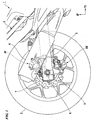
- FIG. 1 shows a rear portion a motorcycle 1, which is taken as an example of a straddle type vehicle that is provided with a brake caliper according to a first embodiment of the present invention.
- reference symbol 2 denotes a vehicle frame, and on the vehicle frame 2, there is supported, in a manner that allows swinging in the up-down direction, the front portion of a pair of left and right swing arms 3 that extend backward.
- a rear axle 4 spans across at the rear portion of the left and right swing arms 3, and on the rear axle 4 there is rotatably supported a rear wheel 5.
- a muffler 6 is arranged on the right hand side of the swing arm 3 arranged.
- a brake disc 7 which rotates integrally with the rear wheel 5.
- the brake disc 7 is sandwiched by a hydraulic brake caliper 8F or a mechanical brake caliper 8M, and it thereby gives a braking force to the rear wheel 5.
- a plate-shaped caliper bracket 9 that extends in the up-down direction.
- the hydraulic brake caliper 8F is supported on the upper portion of the caliper bracket 9, and the mechanical brake caliper 8M is supported on the lower portion of the caliper bracket 9.
- the hydraulic brake caliper 8F and the mechanical brake caliper 8M swing integrally with the swing arm 3. As shown in FIG.
- the hydraulic brake caliper 8F is positioned on the inner side of the muffler 6 with respect to the vehicle widthwise direction.
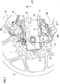
- the outline of the caliper bracket 9 is shown with thick solid lines or broken lines, and in FIG. 1 and FIG. 2 , for the sake of convenience of description, the portion of the outline that does not appear in the outer appearance of the brake disc 7 is shown with two-dot chain lines.
- the hydraulic brake caliper 8F is provided with a caliper body 10F that is supported so as to be able to move along the vehicle widthwise direction with respect to the caliper bracket 9 only by a predetermined distance
- the mechanical brake caliper 8M is provided with a caliper body 10M that is supported so as to be able to move along the vehicle widthwise direction with respect to the caliper bracket 9 only by a predetermined distance.
- the caliper body 10F houses, in a manner of allowing it to slide in the vehicle widthwise direction, a hydraulically operated piston 12 that presses the brake disc 7, and the caliper body 10M houses, in a manner of allowing it to slide in the vehicle widthwise direction, a mechanically operated piston 13 that presses the brake disc 7.
- the axial direction of each of the pistons 12 and 13 is parallel with the vehicle widthwise direction.
- reference symbol 9A denotes a swing arm engagement recess portion 9A in the caliper bracket 9 that is formed in a portion positioned in front of the rear axle 4 and on the inner side of the swing arm 3.
- This swing arm engagement recess portion 9A is positioned below the hydraulic brake caliper 8F and above the mechanical brake caliper 8M, and between the hydraulic brake caliper 8F and the mechanical brake caliper 8M.
- the swing arm engagement recess portion 9A in cooperation with the rear axle 4, swingably supports the caliper bracket 9 by engaging with a protrusion portion 3A provided on the swing arm 3.
- the rear portion of the caliper bracket 9 supports and has the rear axle 4 inserted therethrough.
- a brake hose 14 for supplying pressurized fluid to a cylinder (not shown in the figure) which houses the hydraulically operated piston 12.
- the hydraulically operated piston 12 operates according to the fluid pressure caused by the pressurized fluid supplied from the brake hose 14. To describe in detail, when pressurized fluid is supplied into the cylinder via the brake hose 14, the hydraulically operated piston 12 is propelled to the brake disc 7 side and presses the brake disc 7 via a brake pad (omitted in the figure).
- the brake hose 14 is connected from the caliper body 10F to a master cylinder (not shown in the figure) which is provided at the center lower portion of the motorcycle 1.
- a master cylinder (not shown in the figure) which is provided at the center lower portion of the motorcycle 1.
- a rotation arm 15 that extends upward, and to the tip end portion of the rotation arm 15 there is connected a brake wire 16.
- the brake wire 16 has its one end connected to the rotation arm 15, and the other end thereof is connected to a brake lever, which is an operating element (not shown in the figure) and which is provided at an appropriate location of the vehicle such as the steering bar. As a result of this brake lever being operated, it is pulled and rotates the rotation arm 15.
- the rotation arm 15 extends from the caliper body 10M and is then bent so as to turn back.
- the brake wire 16 is connected to this bent tip end portion.
- the mechanical brake caliper 8M is such that as the brake wire 16 is pulled and the rotation arm 15 is rotated, the mechanically operated piston 13 is propelled to the brake disc 7 side, and presses the brake disc 7 via the brake pad (not shown in the figure).
- the brake lever is configured so that it is releasably retained at a position where the brake wire 16 has been pulled only by a predetermined amount so that the mechanically operated piston 13 can maintain the state of pressing the brake disc 7.
- the mechanical brake caliper 8M configures a parking brake mechanism.
- the brake lever is biased so that when the state of being retained at the position where the brake wire 16 has been pulled by means of the operation only by the predetermined amount is released, it returns to the state prior to this operation, and when the above state is released, the rotation arm 15 also returns to the pre-rotation state.
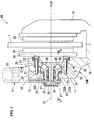
- the caliper body 10M is integrally provided with: a body main body 17 that houses the mechanically operated piston 13 and that is arranged on the vehicle widthwise outer side of the brake disc 7; a bridge portion 18 that extends from the body main body 17 so as to straddle the brake disc 7; and an inner side contact portion 19 that extends from the bridge portion 18 toward the center of the brake disc 7, and that opposes the body main body 17 across the brake disc 7. Between the body main body 17 and the inner side contact portion 19 there are arranged a pair of left and right brake pads 20 so as to be on either side of the brake disc 7.
- brake pads 20 are supported at appropriate positions of the caliper body 10M and are able to move along the axial direction of the mechanically operated piston 13.
- reference symbol C1 denotes the center axis line of the mechanically operated piston 13, and the direction along this center axis line C1 is the axial direction of the mechanically operated piston 13.
- a cylinder 21 that is formed as a hole from the wall portion of the body main body 17, which opposes the brake disc 7 across the right brake pad 20, and that extends toward the vehicle widthwise outer side.
- This cylinder 21 houses the mechanically operated piston 13.
- the mechanically operated piston 13 is formed in a bottom-ended cylindrical shape. In the present embodiment, the mechanically operated piston 13 is housed within the cylinder 21 in a manner such that the opening end portion thereof faces the brake disc 7 side.
- a cross-sectionally circular-shaped cylinder member housing chamber 22 that extends vehicle widthwise outward from the bottom portion of the cylinder 21 and that opens to the outside of the body main body 17.
- this cylinder member housing chamber 22 there is housed a rotation cylinder member 23 that is arranged coaxially with the mechanically operated piston 13 and alongside the mechanically operated piston 13. This rotation cylinder member 23 can rotate about the axial center within the cylinder member housing chamber 22, and is rotatably supported on the caliper body 10M.
- the rotation cylinder member 23 is such that the end portion on the vehicle widthwise outer side projects from the vehicle widthwise outer opening edge of the cylinder member housing chamber 22, and the rotation arm 15 is fixed on this projecting end portion. That is to say, the rotation cylinder member 23 rotates by rotating the rotation arm 15.
- the cylinder member housing chamber 22 is formed in a counter-bore shape in which a major diameter portion 22A that extends vehicle widthwise outward from the bottom portion of the cylinder 21 and that is smaller in diameter than the cylinder 21, and a minor diameter portion 22B that extends vehicle widthwise outward from the major diameter portion 22A and that is smaller in diameter than the major diameter portion 22A, communicate with each other.
- a major diameter portion 22A that extends vehicle widthwise outward from the bottom portion of the cylinder 21 and that is smaller in diameter than the cylinder 21, and a minor diameter portion 22B that extends vehicle widthwise outward from the major diameter portion 22A and that is smaller in diameter than the major diameter portion 22A, communicate with each other.
- the rotation cylinder member 23 at the vehicle widthwise inner side end portion, there is formed a flange portion 24 that extends inward and outward in the radial direction thereof, and the rotation cylinder member 23 is housed in the cylinder member housing chamber 22 so that this flange portion 24 is positioned within the major diameter portion 22
- the surface of the radially outward extending portion of the flange portion 24 that faces the vehicle widthwise outer side opposes a wall portion 22C that is formed between the major diameter portion 22A and the minor diameter portion 22B, and a thrust bearing 25 is provided between this wall portion 22C and the vehicle widthwise outward facing surface of the flange portion 24.
- a ring-shaped seal member 37 is provided at the opening edge portion on the vehicle widthwise outer side of the cylinder member housing chamber 22, at the opening edge portion on the vehicle widthwise outer side of the cylinder member housing chamber 22, there is provided a ring-shaped seal member 37.
- the seal member 37 is in contact, in the axial direction of the rotation cylinder member 23, with the base end portion of the rotation arm 15, and it restricts movement of the rotation cylinder member 23 toward the vehicle widthwise inner side. Accordingly, the rotation cylinder member 23 rotates within the cylinder member housing chamber 22 in a state where movement thereof in the axial direction is restricted.
- a conversion mechanism 26 that converts rotary motion of the rotation cylinder member 23 into axially linear motion of the mechanically operated piston 13, and that presses and extends the mechanically operated piston 13 toward the brake disc 7 side.
- this conversion mechanism 26 employs a so-called cam bearing mechanism which utilizes the commonly known cam effect.
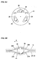
- the conversion mechanism 26 of the present embodiment is such that, on the respective bottom portions of the flange portion 24 of the rotation cylinder member 23, and the mechanically operated piston 13, between a flange side groove 27 and a piston side groove 28 formed concentrically with the center of the mechanically operated piston 13, there is retained rolling bodies 29.
- the flange side groove 27 and the piston side groove 28 are formed in a sloped shape having sloped surfaces (27A, 28A) the depth of which continuously changes with respect to the circumferential direction of the mechanically operated piston 13. Incidentally, in FIG.
- FIG. 8B is a cross-sectional view of the arc plane that includes the line D-D in FIG. 3 and FIG. 8A .
- flange side grooves 27 and the piston side grooves 28 are formed at intervals in the respective bottom portions of the flange portion 24 of the rotation cylinder member 23, and the mechanically operated piston 13, and a single rolling body 29 is retained separately in each of the several flange side grooves 27 and the piston side grooves 28.
- the rolling body 29 can move to the mechanically operated piston 13 side and press the mechanically operated piston 13.
- the flange side groove 27 of the flange portion 24 and the piston side groove 28 of the bottom portion of the mechanically operated piston 13 are each provided as grooves of a circumferentially sloped shape.
- either one of the flange side groove 27 and the piston side groove 28 may be provided in a sloped shape, and the other one may be provided simply as a groove for retaining the rolling body 29.
- the flange side groove 27 and the piston side groove 28 are each provided as a groove of a circumferentially sloped shape. Therefore friction between the rolling body 29 and the flange side groove 27 and the piston side groove 28 can be suppressed further.
- a conversion mechanism similar to the conversion mechanism 26 is described.
- the conversion mechanisms in these second and third embodiments are also configured with a rolling body 29, a flange side groove 27, and a piston side groove 28 similar to those in the first embodiment.
- a plurality of guide members 30, which restrict rotation of the mechanically operated piston 13 with respect to the body main body 17 and which guide axial movement of the mechanically operated piston 13, are provided on the radially outer side of the rotation cylinder member 23.
- These guide members 30, at the outer circumference portion of the bottom portion of the cylinder 21, are fixed by having one end portion side thereof inserted into a plurality of retention holes 31 that are formed at intervals around the circumferential direction of the cylinder 21.
- the other end portion side of the guide member 30 is slidably inserted into an engagement hole 32 formed from the bottom portion of the mechanically operated piston 13 into the circumferential wall portion.
- the return spring 33 that is arranged coaxially with this rotation cylinder member 23 and that biases the mechanically operated piston 13 in the retracting direction (in the direction of moving away from the brake disc 7).
- the return spring 33 has its one end in contact with the portion of the flange portion 24 of the rotation cylinder member 23 that extends radially inward, and has the other end in contact with an engagement projection portion 34 that projects vehicle widthwise outward from the bottom portion center of the mechanically operated piston 13 and that is inserted into the inner side of the rotation cylinder member 23.
- the engagement projection portion 34 passes through the radially inner side of the flange portion 24 and extends vehicle widthwise outward, and on the tip end thereof there is attached a cap 35 with a diameter greater than that of the engagement projection portion 34.
- the other end of the return spring 33 mentioned above is in contact with a surface of the cap 35 facing the flange portion 24 side.
- the return spring 33 contracts when the mechanically operated piston 13 is propelled to the brake disc 7 side, and accumulates a biasing force in the direction so as to retract the mechanically operated piston 13 away from the brake disc 7.
- these rolling body 29, rotation cylinder member 23, and return spring 33 are arranged so that at least part of the rolling body 29 overlaps with the guide member 30 with respect to the radial direction of the mechanically operated piston 13.
- the return spring 33 is arranged coaxially with the rotation cylinder member 23 on the inner side of the rotation cylinder member 23. Therefore there is no need for providing a larger space for the return spring 33 by separately extending it in the axial direction of the mechanically operated piston 13. As a result, it is possible to suppress the dimension of the caliper body 10M in the axial direction of the mechanically operated piston 13. Thereby, it is possible to make compact the dimension in the axial direction of the mechanically operated piston 13.
- the return spring 33 can be protected by the rotation cylinder member 23, and excellent outer appearance can also be achieved.
- the conversion mechanism 26 is configured with the grooves (flange side groove 27 and piston side groove 28) and the rolling body 29 to suppress the thickness, and the guide member 30 that restricts rotation of the mechanically operated piston 13 with respect to the caliper body 10M is provided on the radially outer side of the rotation cylinder member 23.
- the guide member 30 that restricts rotation of the mechanically operated piston 13 with respect to the caliper body 10M is provided on the radially outer side of the rotation cylinder member 23.
- the flange portion 24 is formed on the rotation cylinder member 23, and the thrust bearing 25 is compactly provided to take advantage of the side and base surfaces of this flange portion 24. Therefore, smooth rotation of the rotation cylinder member 23 is possible, and operability can be improved.
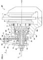
- FIG. 5 a second embodiment of the present invention is described with reference to FIG. 5 .
- the configuration corresponding to the mechanically operated piston 13 and the conversion mechanism 26 in the mechanical brake caliper 8M of the first embodiment differs from that of the first embodiment.
- the same constituents as those in the first embodiment are denoted by the same reference symbols, and descriptions thereof are omitted.
- the conversion mechanism 26 is configured such that a rolling body 29 is retained by a flange side groove 27 that is formed in the flange portion 24 of the rotation cylinder member 23, and a piston side groove 28 that is formed in a circular plate-shaped conversion plate 40 arranged within the cylinder 21, between the bottom portion of the mechanically operated piston 13 and the flange portion 24.
- the shapes of the flange side groove 27 and the piston side groove 28 are similar to those in the first embodiment.
- the conversion plate 40 is housed within the cylinder 21 so as to be able to slide in the axial direction of the mechanically operated piston 13, and a guide member 30 passes through the outer circumferential portion thereof.
- the guide member 30 restricts rotation of the conversion plate 40 and only restricts axial movement of the mechanically operated piston 13, and is not inserted in the mechanically operated piston 13.
- the mechanically operated piston 13 and the conversion plate 40 move integrally. Therefore rotation is indirectly restricted and guided by the guide member 30.
- the engagement projection portion 34 of the mechanically operated piston 13 On the outer circumferential surface of the engagement projection portion 34 of the mechanically operated piston 13 there is formed a male threaded portion 45, and the engagement projection portion 34 is inserted in the projection cylinder portion 42 in a state of the male threaded portion 45 being threadably engaged with the female threaded portion 44.
- the mechanically operated piston 13 by rotating the mechanically operated piston 13 relative to the conversion plate 40, the mechanically operated piston 13 can be moved in the axial direction relatively to the conversion plate 40.
- the engagement projection portion 34 projects vehicle widthwise outward from the projection cylinder portion 42, and on the outer circumferential surface of the tip end portion of the engagement projection portion 34 projecting from the projection cylinder portion 42, there is screwed a positioning nut 46.
- the positioning nut 46 is in contact with the spring receiving flange portion 43.
- a tool socket 47 for inserting therein a tool for rotating the mechanically operated piston 13 with respect to the conversion plate 40.
- this mechanical brake caliper 8M' by inserting a tool into the tool socket 47 in the tip end of the engagement projection portion 34, and rotating the mechanically operated piston 13 relatively to the conversion plate 40, the axial position of the mechanically operated piston 13 relative to the conversion plate 40 can be adjusted regardless of rotation of the rotation cylinder member 23.
- the distance from the conversion plate 40 changes with respect to the state prior to adjustment.
- the projection cylinder portion 42 of the conversion mechanism 40 and the engagement projection portion 34 of the mechanically operated piston 13 are threadably engaged and integrated, it is possible to receive a constant conversion amount of linear motion converted by the conversion mechanism 26 with respect to the rotation of the rotation cylinder member 23 regardless of the position relative to the conversion plate 40.
- the conversion mechanism 26 when converting rotary motion of the rotation cylinder member 23 into axially linear motion of the mechanically operated piston 13, the conversion mechanism 26 includes the conversion plate 40 which is a movable member that moves integrally with the mechanically operated piston 13, and the mechanically operated piston 13 and the conversion plate 40 are integrated by means of threadable engagement. Moreover, by rotating the mechanically operated piston 13 relatively to the conversion plate 40, it is possible to adjust the amount of projection of the mechanically operated piston 13 to the brake disc 7 side with respect to the conversion plate 40.
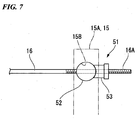
- FIG. 6 and FIG. 7 a third embodiment that does not form part of the present invention is described with reference to FIG. 6 and FIG. 7 .
- the present embodiment is similar to the second embodiment in the point that position can be adjusted with respect to the piston axial direction.
- the arrangement and configuration of the return spring 33 differ from those of the second embodiment, and the shape of the spring receiving flange portion 43 also differs from that of the second embodiment.
- the same constituents as those in the first and second embodiments are denoted by the same reference symbols, and descriptions thereof are omitted.
- the return spring 33 is arranged coaxially with the rotation cylinder member 23, on the radially outer side of the rotation cylinder member 23.
- the return spring 33 has its one end in contact with the rotation arm 15, and its other end in contact with the spring receiving flange portion 43.
- an arm portion 50 that projects radially outward, and the tip end of the arm portion 50 is bent and exhibits a circular shape.
- an adjustment nut 46 By grasping the tip end portion of this type of arm portion 50, the operator can easily perform a rotation operation of an adjustment nut 46 for example.
- the figure illustrates the tip end of the arm portion 50 as though it is positioned in the upper portion of the rotation arm 15 and overlaps with the rotation arm 15, however, these are not connected.
- a plurality of radially inward-depressed engagement grooves 40A are formed, in a manner of being lined around the circumferential direction at intervals, in the outer circumferential portion of the conversion plate 40.
- engagement projection portions 21A that engage with the engagement grooves 40A so as to extend along the axial direction of the mechanically operated piston 13. The engagement projection portions 21A restrict rotation of the conversion plate 40, while guiding the conversion plate 40 in the axial direction of the mechanically operated piston 13.
- the rotation arm 15 differs from those in the first and second embodiments in the shape of the tip end portion.
- a brake wire 16 (refer to FIG. 1 ) is connected to the engagement portion 15A.
- an adjustment mechanism 51 that is capable of adjusting the length of the brake wire 16 between a brake lever, which is an operating element, provided in an appropriate position of the vehicle, and the rotation arm 15.
- the adjustment mechanism 51 is shown with two-dot chain lines.
- the brake wire 16 has, on the tip end portion thereof, a rod portion 16A having a male threaded portion formed thereon.
- a through hole 15B respectively in the opposing portions of the bifurcated engagement portion 15A, there is formed a through hole 15B, and in these through holes 15 there is inserted a column-shaped latching member 52, which is a member of the adjustment mechanism 51, in a bridging manner.
- the rod portion 16A passes through the latching member 52, and an adjustment nut 53 is screwed on the rod portion 16A that has passed through.
- the adjustment nut 53 is in contact with the latching member 52 and is latched on the latching member 52.
- the adjustment mechanism 51 is configured with the latching member 52 and the adjustment nut 53. In this type of adjustment mechanism 51, by screwing the adjustment nut 53 to the latching member 52 side, the brake wire 16 can be pulled, and by rotating the adjustment nut 53 in the direction to come off from the rod portion 16A, tension of the brake wire 16 can be mitigated.
- the portion of the adjustment nut 53 that is in contact with the latching member 52 side is formed in an arc shape around the circumferential surface of the latching member 52.
- the amount of play of the brake wire 16 can be adjusted from the mechanical brake caliper 8M" side. Therefore operability can be improved. That is to say, it is possible to adjust the amount of projection of the mechanically operated piston 13 from the caliper body 10M.
- an adjustment mechanism 51 described in the third embodiment may be added in the first embodiment and the second embodiment.
- the position of the mechanically operated piston 13 relative to the conversion mechanism 26 can be adjusted. Therefore, the amount of projection of the mechanically operated piston 13 from the caliper body 10M can be suitably adjusted without providing an adjustment mechanism 51. Moreover it is effective to provide an adjustment mechanism 51 in a configuration that is not capable of making adjustment to the position of the mechanically operated piston 13 relative to the conversion mechanism 26, as in the configuration of the first embodiment.
Landscapes
- Engineering & Computer Science (AREA)
- General Engineering & Computer Science (AREA)
- Mechanical Engineering (AREA)
- Physics & Mathematics (AREA)
- Fluid Mechanics (AREA)
- Braking Arrangements (AREA)
- Transmission Of Braking Force In Braking Systems (AREA)
Claims (9)
- Bremssattel, umfassend:einen Sattelkörper (10M), welcher gleitbar einen Kolben (13) aufnimmt, welcher auf eine Bremsscheibe (7) drückt;ein Rotations-Zylinderelement (23), welches längs des Kolbens (13), koaxial zu dem Kolben (13), angeordnet ist, und welches an dem Sattelkörper (10M) rotierbar gehaltert ist;einen Rotationsarm (15), welcher an dem Rotations-Zylinderelement (23) befestigt ist, und welcher das Rotations-Zylinderelement (23) mittels einer Betätigung eines Betätigungselements rotiert; undeinen Übersetzungsmechanismus (26), welcher zwischen dem Rotations-Zylinderelement (23) und dem Kolben (13) bereitgestellt ist, und welcher eine Drehbewegung des Rotations-Zylinderelements (23) in eine axiale Linearbewegung des Kolbens (13) übersetzt, um dadurch den Kolben (13) in Richtung der Seite der Bremsscheibe (7) zu drücken und zu bewegen,dadurch gekennzeichnet, dassferner eine Rückstellfeder (33) bereitgestellt ist, welche koaxial zu dem Rotations-Zylinderelement (23) an einer radial inneren Seite des Rotations-Zylinderelements (23) angeordnet ist, und welche den Kolben (13) in einer Bewegungsrichtung weg von der Bremsscheibe (7) vorspannt.
- Bremssattel nach Anspruch 1, wobei der Kolben (13) mit einem Durchmesser gebildet ist, welcher größer als der des Rotations-Zylinderelements (23) ist, und wobei an der radial äußeren Seite des Rotations-Zylinderelements (23) ein Führungselement (30) bereitgestellt ist, welches eine Rotation des Kolbens (13) in Bezug auf den Sattelkörper (10M) begrenzt, und welches eine Bewegung des Kolbens (13) in der axialen Richtung führt.
- Bremssattel nach Anspruch 2, wobei an einem Endabschnitt des Rotations-Zylinderelements (23) an der Seite des Kolbens (13) ein Flanschabschnitt (24) gebildet ist, welcher sich in Bezug auf die radiale Richtung nach außen erstreckt, und an einer Fläche dieses Flanschabschnitts (24), welche zu der Seite des Kolbens (13) weist, ein Wirkungsabschnitt (27) zum Veranlassen des Kolbens (13), eine Linearbewegung durchzuführen, gebildet ist; und wobei an einer gegenüberliegenden Seite eine Fläche des Flanschabschnitts (24), welche zu der Seite des Kolbens (13) weist, innerhalb des Sattelkörpers (10M), einem Teil des Sattelkörpers (10M) gegenübersteht, und zwischen diesem einen Teil und der Fläche an der gegenüberliegenden Seite eine Schublagerung (25) bereitgestellt ist.
- Bremssattel nach Anspruch 3, wobei der Übersetzungsmechanismus (26) derart ist, dass:ein Rollkörper (29) zwischen einer Umfangsnut (27), welche der Wirkungsabschnitt (27) des Rotations-Zylinderelements (23) ist, und einer Umfangsnut (28) gehalten ist, welche in dem Kolben (13) gebildet ist;und wenigstens eine aus der Umfangsnut (27), welche in dem Rotations-Zylinderelement (23) gebildet ist, und der Umfangsnut (28), welche in den Kolben (13) gebildet ist, eine angeschrägte Fläche (27A, 28A) aufweist, welche die Nuttiefe in Bezug auf eine Umfangsrichtung des Kolbens (13) ändert.
- Bremssattel nach Anspruch 3, wobei
der Übersetzungsmechanismus (26) ein bewegliches Element (40) aufweist, welches sich integral mit dem Kolben (13) bewegt, wenn eine Drehbewegung des Rotations-Zylinderelements (23) in eine axiale Linearbewegung des Kolbens (13) übersetzt wird;
und der Kolben (13) und das bewegliche Element (40) schraubbar gekoppelt und dadurch integriert sind, und eine Menge eines Vorstehens des Kolbens (13) in Richtung der Seite der Bremsscheibe (7) in Bezug auf das bewegliche Element (40) durch Rotation des Kolbens (13) relativ zu dem beweglichen Element (40) eingestellt ist. - Bremssattel nach Anspruch 5, wobei der Übersetzungsmechanismus (26) derart ist, dass:ein Rollkörper (29) zwischen einer Umfangsnut (27), welche der Wirkungsabschnitt (27) des Rotations-Zylinderelements (23) ist, und einer Umfangsnut (28) gehalten ist, welche in dem beweglichen Element (40) gebildet ist;und wenigstens eine aus der Umfangsnut (27), welche in dem Rotations-Zylinderelement (23) gebildet ist, und der Umfangsnut (28), welche in dem beweglichen Element (40) gebildet ist, eine angeschrägte Fläche (27A, 28A) aufweist, welche die Nuttiefe in Bezug auf eine Umfangsrichtung des Kolbens (13) ändert.
- Bremssattel nach Anspruch 4 oder 6, wobei der Rollkörper (29), das Rotations-Zylinderelement (23) und die Rückstellfeder (33) derart angeordnet sind, so dass wenigstens ein Teil des Rollkörpers (29) mit dem Führungselement (30) in der radialen Richtung des Kolbens (13) überlappt.
- Bremssattel nach einem der Ansprüche 1 bis 7, wobei die Rückstellfeder (33) so angeordnet ist, dass die gesamte Länge davon innerhalb der inneren Seite des Rotations-Zylinderelements (23) in Bezug auf die axiale Richtung aufgenommen ist.
- Bremssattel nach einem der Ansprüche 1 bis 8, wobei das Betätigungselement und der Rotationsarm (15) durch einen Draht (16) verbunden sind und ein Einstellmechanismus (51) bereitgestellt ist, welcher in der Lage ist, die Länge des Drahts (16) zwischen dem
Applications Claiming Priority (2)
| Application Number | Priority Date | Filing Date | Title |
|---|---|---|---|
| JP2012218546 | 2012-09-28 | ||
| PCT/JP2013/064246 WO2014050205A1 (ja) | 2012-09-28 | 2013-05-22 | ブレーキキャリパ |
Publications (3)
| Publication Number | Publication Date |
|---|---|
| EP2865916A1 EP2865916A1 (de) | 2015-04-29 |
| EP2865916A4 EP2865916A4 (de) | 2015-12-02 |
| EP2865916B1 true EP2865916B1 (de) | 2016-10-19 |
Family
ID=50387624
Family Applications (1)
| Application Number | Title | Priority Date | Filing Date |
|---|---|---|---|
| EP13842883.4A Not-in-force EP2865916B1 (de) | 2012-09-28 | 2013-05-22 | Bremssattel |
Country Status (6)
| Country | Link |
|---|---|
| US (1) | US9440705B2 (de) |
| EP (1) | EP2865916B1 (de) |
| JP (1) | JP5842064B2 (de) |
| CN (1) | CN104704256B (de) |
| TW (1) | TWI522547B (de) |
| WO (1) | WO2014050205A1 (de) |
Families Citing this family (4)
| Publication number | Priority date | Publication date | Assignee | Title |
|---|---|---|---|---|
| CN105197165A (zh) * | 2015-09-25 | 2015-12-30 | 温州市明派车辆部件有限公司 | 机械式碟刹装置 |
| TWI680241B (zh) * | 2018-03-26 | 2019-12-21 | 黃奕誠 | 機械式碟剎結構改良 |
| CN111271398A (zh) * | 2020-03-17 | 2020-06-12 | 武汉万向汽车制动器有限公司 | 汽车盘式制动器 |
| CN111469963B (zh) * | 2020-04-13 | 2021-07-30 | 深圳市捷康实业有限公司 | 自行车刹车系统 |
Family Cites Families (14)
| Publication number | Priority date | Publication date | Assignee | Title |
|---|---|---|---|---|
| FR2041002A1 (de) * | 1969-04-22 | 1971-01-29 | Dba | |
| US3920102A (en) * | 1973-01-19 | 1975-11-18 | Tokico Ltd | Disc brake actuating and adjusting mechanism |
| GB1451327A (en) | 1973-02-23 | 1976-09-29 | Girling Ltd | Brake actuator mechanisms provided with automatic slack adjusters |
| JPS5153559Y2 (de) | 1973-09-22 | 1976-12-21 | ||
| CA1058532A (en) | 1975-02-17 | 1979-07-17 | Tokico Ltd. | Mechanical type disc brake |
| JPS5267460A (en) * | 1975-10-20 | 1977-06-03 | Tokico Ltd | Mechanical disc brake |
| JPH0417873Y2 (de) | 1987-09-30 | 1992-04-21 | ||
| DE8900277U1 (de) * | 1989-01-11 | 1990-05-10 | Lucas Industries P.L.C., Birmingham, West Midlands | Betätigungsvorrichtung mit selbsttätiger Nachstellung für eine Fahrzeugbremse |
| DE4031616C2 (de) * | 1990-10-05 | 1999-11-25 | Perrot Bremse Gmbh Deutsche | Automatische Nachstelleinrichtung für eine mechanisch betätigte Gleitsattel-Scheibenbremse |
| JPH0921433A (ja) * | 1995-07-06 | 1997-01-21 | Akebono Brake Ind Co Ltd | パーキング用メカニカルディスクブレーキ |
| US6422354B1 (en) * | 2000-12-21 | 2002-07-23 | Delphi Technologies, Inc. | Disc brake caliper with integral parking brake |
| JP2004169729A (ja) * | 2002-11-18 | 2004-06-17 | Akebono Brake Ind Co Ltd | 電動ディスクブレーキ |
| JP2007146957A (ja) | 2005-11-28 | 2007-06-14 | Nissin Kogyo Co Ltd | ディスクブレーキ装置 |
| CN201818678U (zh) * | 2010-08-05 | 2011-05-04 | 利奇机械工业股份有限公司 | 机械式碟刹卡钳 |
-
2013
- 2013-05-22 CN CN201380049926.3A patent/CN104704256B/zh not_active Expired - Fee Related
- 2013-05-22 US US14/416,400 patent/US9440705B2/en not_active Expired - Fee Related
- 2013-05-22 EP EP13842883.4A patent/EP2865916B1/de not_active Not-in-force
- 2013-05-22 JP JP2014538225A patent/JP5842064B2/ja not_active Expired - Fee Related
- 2013-05-22 WO PCT/JP2013/064246 patent/WO2014050205A1/ja not_active Ceased
- 2013-05-23 TW TW102118197A patent/TWI522547B/zh not_active IP Right Cessation
Also Published As
| Publication number | Publication date |
|---|---|
| US20150203170A1 (en) | 2015-07-23 |
| WO2014050205A1 (ja) | 2014-04-03 |
| EP2865916A1 (de) | 2015-04-29 |
| CN104704256B (zh) | 2017-05-24 |
| JPWO2014050205A1 (ja) | 2016-08-22 |
| EP2865916A4 (de) | 2015-12-02 |
| TWI522547B (zh) | 2016-02-21 |
| TW201413133A (zh) | 2014-04-01 |
| JP5842064B2 (ja) | 2016-01-13 |
| US9440705B2 (en) | 2016-09-13 |
| CN104704256A (zh) | 2015-06-10 |
Similar Documents
| Publication | Publication Date | Title |
|---|---|---|
| EP2865916B1 (de) | Bremssattel | |
| JP6129971B2 (ja) | ブレーキシリンダ装置及びディスクブレーキ装置 | |
| EP3045760B1 (de) | Bremsvorrichtung | |
| JP6438327B2 (ja) | ブレーキ装置 | |
| JP6514642B2 (ja) | パーキングブレーキユニット | |
| US11143251B2 (en) | Disk brake | |
| JP2011052734A (ja) | ディスクブレーキ | |
| KR102488518B1 (ko) | 전자식 캘리퍼 브레이크 | |
| JP5111894B2 (ja) | ユニットブレーキ | |
| JP5889764B2 (ja) | ブレーキキャリパ及びそれを備えた鞍乗型車両 | |
| JP5387830B2 (ja) | 電動ディスクブレーキ | |
| EP2191160B1 (de) | Elastisches druckglied für einen kombinierten sattel | |
| EP4151878B1 (de) | Bremssattel | |
| JP2010060122A (ja) | アジャスタロッド回止め機構 | |
| JP2008275034A (ja) | ディスクブレーキ装置 | |
| US20180216683A1 (en) | Disc brake | |
| JP4130351B2 (ja) | ディスクブレーキ | |
| JP2014005845A (ja) | ブレーキ装置 |
Legal Events
| Date | Code | Title | Description |
|---|---|---|---|
| PUAI | Public reference made under article 153(3) epc to a published international application that has entered the european phase |
Free format text: ORIGINAL CODE: 0009012 |
|
| 17P | Request for examination filed |
Effective date: 20150123 |
|
| AK | Designated contracting states |
Kind code of ref document: A1 Designated state(s): AL AT BE BG CH CY CZ DE DK EE ES FI FR GB GR HR HU IE IS IT LI LT LU LV MC MK MT NL NO PL PT RO RS SE SI SK SM TR |
|
| AX | Request for extension of the european patent |
Extension state: BA ME |
|
| RA4 | Supplementary search report drawn up and despatched (corrected) |
Effective date: 20151103 |
|
| RIC1 | Information provided on ipc code assigned before grant |
Ipc: F16D 65/14 20060101ALI20151028BHEP Ipc: F16D 65/46 20060101ALI20151028BHEP Ipc: B62L 3/00 20060101ALI20151028BHEP Ipc: F16D 65/18 20060101AFI20151028BHEP |
|
| DAX | Request for extension of the european patent (deleted) | ||
| GRAP | Despatch of communication of intention to grant a patent |
Free format text: ORIGINAL CODE: EPIDOSNIGR1 |
|
| INTG | Intention to grant announced |
Effective date: 20160520 |
|
| RIN1 | Information on inventor provided before grant (corrected) |
Inventor name: NAGAI, RYUICHI Inventor name: KAWASAKI, SHINJI Inventor name: TOYODA, HIDETOSHI Inventor name: NAKAIE, HIROKATSU Inventor name: MATSUI, YASUMASA Inventor name: ITO, SHINJI |
|
| GRAS | Grant fee paid |
Free format text: ORIGINAL CODE: EPIDOSNIGR3 |
|
| GRAA | (expected) grant |
Free format text: ORIGINAL CODE: 0009210 |
|
| AK | Designated contracting states |
Kind code of ref document: B1 Designated state(s): AL AT BE BG CH CY CZ DE DK EE ES FI FR GB GR HR HU IE IS IT LI LT LU LV MC MK MT NL NO PL PT RO RS SE SI SK SM TR |
|
| REG | Reference to a national code |
Ref country code: GB Ref legal event code: FG4D |
|
| REG | Reference to a national code |
Ref country code: CH Ref legal event code: EP |
|
| REG | Reference to a national code |
Ref country code: AT Ref legal event code: REF Ref document number: 838627 Country of ref document: AT Kind code of ref document: T Effective date: 20161115 |
|
| REG | Reference to a national code |
Ref country code: IE Ref legal event code: FG4D |
|
| REG | Reference to a national code |
Ref country code: DE Ref legal event code: R096 Ref document number: 602013013109 Country of ref document: DE |
|
| REG | Reference to a national code |
Ref country code: NL Ref legal event code: MP Effective date: 20161019 |
|
| REG | Reference to a national code |
Ref country code: LT Ref legal event code: MG4D |
|
| PG25 | Lapsed in a contracting state [announced via postgrant information from national office to epo] |
Ref country code: LV Free format text: LAPSE BECAUSE OF FAILURE TO SUBMIT A TRANSLATION OF THE DESCRIPTION OR TO PAY THE FEE WITHIN THE PRESCRIBED TIME-LIMIT Effective date: 20161019 |
|
| REG | Reference to a national code |
Ref country code: AT Ref legal event code: MK05 Ref document number: 838627 Country of ref document: AT Kind code of ref document: T Effective date: 20161019 |
|
| PG25 | Lapsed in a contracting state [announced via postgrant information from national office to epo] |
Ref country code: GR Free format text: LAPSE BECAUSE OF FAILURE TO SUBMIT A TRANSLATION OF THE DESCRIPTION OR TO PAY THE FEE WITHIN THE PRESCRIBED TIME-LIMIT Effective date: 20170120 Ref country code: SE Free format text: LAPSE BECAUSE OF FAILURE TO SUBMIT A TRANSLATION OF THE DESCRIPTION OR TO PAY THE FEE WITHIN THE PRESCRIBED TIME-LIMIT Effective date: 20161019 Ref country code: LT Free format text: LAPSE BECAUSE OF FAILURE TO SUBMIT A TRANSLATION OF THE DESCRIPTION OR TO PAY THE FEE WITHIN THE PRESCRIBED TIME-LIMIT Effective date: 20161019 Ref country code: NO Free format text: LAPSE BECAUSE OF FAILURE TO SUBMIT A TRANSLATION OF THE DESCRIPTION OR TO PAY THE FEE WITHIN THE PRESCRIBED TIME-LIMIT Effective date: 20170119 |
|
| REG | Reference to a national code |
Ref country code: FR Ref legal event code: PLFP Year of fee payment: 5 |
|
| PG25 | Lapsed in a contracting state [announced via postgrant information from national office to epo] |
Ref country code: PT Free format text: LAPSE BECAUSE OF FAILURE TO SUBMIT A TRANSLATION OF THE DESCRIPTION OR TO PAY THE FEE WITHIN THE PRESCRIBED TIME-LIMIT Effective date: 20170220 Ref country code: FI Free format text: LAPSE BECAUSE OF FAILURE TO SUBMIT A TRANSLATION OF THE DESCRIPTION OR TO PAY THE FEE WITHIN THE PRESCRIBED TIME-LIMIT Effective date: 20161019 Ref country code: RS Free format text: LAPSE BECAUSE OF FAILURE TO SUBMIT A TRANSLATION OF THE DESCRIPTION OR TO PAY THE FEE WITHIN THE PRESCRIBED TIME-LIMIT Effective date: 20161019 Ref country code: AT Free format text: LAPSE BECAUSE OF FAILURE TO SUBMIT A TRANSLATION OF THE DESCRIPTION OR TO PAY THE FEE WITHIN THE PRESCRIBED TIME-LIMIT Effective date: 20161019 Ref country code: ES Free format text: LAPSE BECAUSE OF FAILURE TO SUBMIT A TRANSLATION OF THE DESCRIPTION OR TO PAY THE FEE WITHIN THE PRESCRIBED TIME-LIMIT Effective date: 20161019 Ref country code: BE Free format text: LAPSE BECAUSE OF FAILURE TO SUBMIT A TRANSLATION OF THE DESCRIPTION OR TO PAY THE FEE WITHIN THE PRESCRIBED TIME-LIMIT Effective date: 20161019 Ref country code: NL Free format text: LAPSE BECAUSE OF FAILURE TO SUBMIT A TRANSLATION OF THE DESCRIPTION OR TO PAY THE FEE WITHIN THE PRESCRIBED TIME-LIMIT Effective date: 20161019 Ref country code: PL Free format text: LAPSE BECAUSE OF FAILURE TO SUBMIT A TRANSLATION OF THE DESCRIPTION OR TO PAY THE FEE WITHIN THE PRESCRIBED TIME-LIMIT Effective date: 20161019 Ref country code: HR Free format text: LAPSE BECAUSE OF FAILURE TO SUBMIT A TRANSLATION OF THE DESCRIPTION OR TO PAY THE FEE WITHIN THE PRESCRIBED TIME-LIMIT Effective date: 20161019 Ref country code: IS Free format text: LAPSE BECAUSE OF FAILURE TO SUBMIT A TRANSLATION OF THE DESCRIPTION OR TO PAY THE FEE WITHIN THE PRESCRIBED TIME-LIMIT Effective date: 20170219 |
|
| REG | Reference to a national code |
Ref country code: DE Ref legal event code: R097 Ref document number: 602013013109 Country of ref document: DE |
|
| PG25 | Lapsed in a contracting state [announced via postgrant information from national office to epo] |
Ref country code: DK Free format text: LAPSE BECAUSE OF FAILURE TO SUBMIT A TRANSLATION OF THE DESCRIPTION OR TO PAY THE FEE WITHIN THE PRESCRIBED TIME-LIMIT Effective date: 20161019 Ref country code: EE Free format text: LAPSE BECAUSE OF FAILURE TO SUBMIT A TRANSLATION OF THE DESCRIPTION OR TO PAY THE FEE WITHIN THE PRESCRIBED TIME-LIMIT Effective date: 20161019 Ref country code: CZ Free format text: LAPSE BECAUSE OF FAILURE TO SUBMIT A TRANSLATION OF THE DESCRIPTION OR TO PAY THE FEE WITHIN THE PRESCRIBED TIME-LIMIT Effective date: 20161019 Ref country code: SK Free format text: LAPSE BECAUSE OF FAILURE TO SUBMIT A TRANSLATION OF THE DESCRIPTION OR TO PAY THE FEE WITHIN THE PRESCRIBED TIME-LIMIT Effective date: 20161019 Ref country code: RO Free format text: LAPSE BECAUSE OF FAILURE TO SUBMIT A TRANSLATION OF THE DESCRIPTION OR TO PAY THE FEE WITHIN THE PRESCRIBED TIME-LIMIT Effective date: 20161019 |
|
| PLBE | No opposition filed within time limit |
Free format text: ORIGINAL CODE: 0009261 |
|
| STAA | Information on the status of an ep patent application or granted ep patent |
Free format text: STATUS: NO OPPOSITION FILED WITHIN TIME LIMIT |
|
| PG25 | Lapsed in a contracting state [announced via postgrant information from national office to epo] |
Ref country code: SM Free format text: LAPSE BECAUSE OF FAILURE TO SUBMIT A TRANSLATION OF THE DESCRIPTION OR TO PAY THE FEE WITHIN THE PRESCRIBED TIME-LIMIT Effective date: 20161019 Ref country code: LU Free format text: LAPSE BECAUSE OF NON-PAYMENT OF DUE FEES Effective date: 20170531 Ref country code: BG Free format text: LAPSE BECAUSE OF FAILURE TO SUBMIT A TRANSLATION OF THE DESCRIPTION OR TO PAY THE FEE WITHIN THE PRESCRIBED TIME-LIMIT Effective date: 20170119 |
|
| 26N | No opposition filed |
Effective date: 20170720 |
|
| PG25 | Lapsed in a contracting state [announced via postgrant information from national office to epo] |
Ref country code: SI Free format text: LAPSE BECAUSE OF FAILURE TO SUBMIT A TRANSLATION OF THE DESCRIPTION OR TO PAY THE FEE WITHIN THE PRESCRIBED TIME-LIMIT Effective date: 20161019 |
|
| REG | Reference to a national code |
Ref country code: CH Ref legal event code: PL |
|
| GBPC | Gb: european patent ceased through non-payment of renewal fee |
Effective date: 20170522 |
|
| PG25 | Lapsed in a contracting state [announced via postgrant information from national office to epo] |
Ref country code: MC Free format text: LAPSE BECAUSE OF FAILURE TO SUBMIT A TRANSLATION OF THE DESCRIPTION OR TO PAY THE FEE WITHIN THE PRESCRIBED TIME-LIMIT Effective date: 20161019 |
|
| REG | Reference to a national code |
Ref country code: IE Ref legal event code: MM4A |
|
| PG25 | Lapsed in a contracting state [announced via postgrant information from national office to epo] |
Ref country code: CH Free format text: LAPSE BECAUSE OF NON-PAYMENT OF DUE FEES Effective date: 20170531 Ref country code: LI Free format text: LAPSE BECAUSE OF NON-PAYMENT OF DUE FEES Effective date: 20170531 |
|
| PG25 | Lapsed in a contracting state [announced via postgrant information from national office to epo] |
Ref country code: LU Free format text: LAPSE BECAUSE OF NON-PAYMENT OF DUE FEES Effective date: 20170522 |
|
| REG | Reference to a national code |
Ref country code: FR Ref legal event code: PLFP Year of fee payment: 6 |
|
| PG25 | Lapsed in a contracting state [announced via postgrant information from national office to epo] |
Ref country code: GB Free format text: LAPSE BECAUSE OF NON-PAYMENT OF DUE FEES Effective date: 20170522 Ref country code: IE Free format text: LAPSE BECAUSE OF NON-PAYMENT OF DUE FEES Effective date: 20170522 |
|
| PGFP | Annual fee paid to national office [announced via postgrant information from national office to epo] |
Ref country code: FR Payment date: 20180411 Year of fee payment: 6 |
|
| PG25 | Lapsed in a contracting state [announced via postgrant information from national office to epo] |
Ref country code: MT Free format text: LAPSE BECAUSE OF NON-PAYMENT OF DUE FEES Effective date: 20170522 |
|
| PG25 | Lapsed in a contracting state [announced via postgrant information from national office to epo] |
Ref country code: HU Free format text: LAPSE BECAUSE OF FAILURE TO SUBMIT A TRANSLATION OF THE DESCRIPTION OR TO PAY THE FEE WITHIN THE PRESCRIBED TIME-LIMIT; INVALID AB INITIO Effective date: 20130522 |
|
| PGFP | Annual fee paid to national office [announced via postgrant information from national office to epo] |
Ref country code: IT Payment date: 20190527 Year of fee payment: 7 Ref country code: DE Payment date: 20190508 Year of fee payment: 7 |
|
| PG25 | Lapsed in a contracting state [announced via postgrant information from national office to epo] |
Ref country code: CY Free format text: LAPSE BECAUSE OF FAILURE TO SUBMIT A TRANSLATION OF THE DESCRIPTION OR TO PAY THE FEE WITHIN THE PRESCRIBED TIME-LIMIT Effective date: 20161019 |
|
| PG25 | Lapsed in a contracting state [announced via postgrant information from national office to epo] |
Ref country code: MK Free format text: LAPSE BECAUSE OF FAILURE TO SUBMIT A TRANSLATION OF THE DESCRIPTION OR TO PAY THE FEE WITHIN THE PRESCRIBED TIME-LIMIT Effective date: 20161019 |
|
| REG | Reference to a national code |
Ref country code: DE Ref legal event code: R084 Ref document number: 602013013109 Country of ref document: DE |
|
| PG25 | Lapsed in a contracting state [announced via postgrant information from national office to epo] |
Ref country code: TR Free format text: LAPSE BECAUSE OF FAILURE TO SUBMIT A TRANSLATION OF THE DESCRIPTION OR TO PAY THE FEE WITHIN THE PRESCRIBED TIME-LIMIT Effective date: 20161019 |
|
| PG25 | Lapsed in a contracting state [announced via postgrant information from national office to epo] |
Ref country code: FR Free format text: LAPSE BECAUSE OF NON-PAYMENT OF DUE FEES Effective date: 20190531 |
|
| PG25 | Lapsed in a contracting state [announced via postgrant information from national office to epo] |
Ref country code: AL Free format text: LAPSE BECAUSE OF FAILURE TO SUBMIT A TRANSLATION OF THE DESCRIPTION OR TO PAY THE FEE WITHIN THE PRESCRIBED TIME-LIMIT Effective date: 20161019 |
|
| REG | Reference to a national code |
Ref country code: DE Ref legal event code: R119 Ref document number: 602013013109 Country of ref document: DE |
|
| PG25 | Lapsed in a contracting state [announced via postgrant information from national office to epo] |
Ref country code: DE Free format text: LAPSE BECAUSE OF NON-PAYMENT OF DUE FEES Effective date: 20201201 |
|
| PG25 | Lapsed in a contracting state [announced via postgrant information from national office to epo] |
Ref country code: IT Free format text: LAPSE BECAUSE OF NON-PAYMENT OF DUE FEES Effective date: 20200522 |