EP2868601A1 - Dispositif de transport destiné au transport de pièces, notamment de cartes de circuit imprimé, dans une direction de convoyage le long d'une ligne de convoyage - Google Patents
Dispositif de transport destiné au transport de pièces, notamment de cartes de circuit imprimé, dans une direction de convoyage le long d'une ligne de convoyage Download PDFInfo
- Publication number
- EP2868601A1 EP2868601A1 EP20130005442 EP13005442A EP2868601A1 EP 2868601 A1 EP2868601 A1 EP 2868601A1 EP 20130005442 EP20130005442 EP 20130005442 EP 13005442 A EP13005442 A EP 13005442A EP 2868601 A1 EP2868601 A1 EP 2868601A1
- Authority
- EP
- European Patent Office
- Prior art keywords
- conveying
- workpiece
- spacer
- movement
- workpieces
- Prior art date
- Legal status (The legal status is an assumption and is not a legal conclusion. Google has not performed a legal analysis and makes no representation as to the accuracy of the status listed.)
- Withdrawn
Links
Images



Classifications
-
- B—PERFORMING OPERATIONS; TRANSPORTING
- B65—CONVEYING; PACKING; STORING; HANDLING THIN OR FILAMENTARY MATERIAL
- B65G—TRANSPORT OR STORAGE DEVICES, e.g. CONVEYORS FOR LOADING OR TIPPING, SHOP CONVEYOR SYSTEMS OR PNEUMATIC TUBE CONVEYORS
- B65G47/00—Article or material-handling devices associated with conveyors; Methods employing such devices
- B65G47/22—Devices influencing the relative position or the attitude of articles during transit by conveyors
- B65G47/26—Devices influencing the relative position or the attitude of articles during transit by conveyors arranging the articles, e.g. varying spacing between individual articles
- B65G47/30—Devices influencing the relative position or the attitude of articles during transit by conveyors arranging the articles, e.g. varying spacing between individual articles during transit by a series of conveyors
-
- B—PERFORMING OPERATIONS; TRANSPORTING
- B65—CONVEYING; PACKING; STORING; HANDLING THIN OR FILAMENTARY MATERIAL
- B65G—TRANSPORT OR STORAGE DEVICES, e.g. CONVEYORS FOR LOADING OR TIPPING, SHOP CONVEYOR SYSTEMS OR PNEUMATIC TUBE CONVEYORS
- B65G15/00—Conveyors having endless load-conveying surfaces, i.e. belts and like continuous members, to which tractive effort is transmitted by means other than endless driving elements of similar configuration
- B65G15/22—Conveyors having endless load-conveying surfaces, i.e. belts and like continuous members, to which tractive effort is transmitted by means other than endless driving elements of similar configuration comprising a series of co-operating units
-
- B—PERFORMING OPERATIONS; TRANSPORTING
- B65—CONVEYING; PACKING; STORING; HANDLING THIN OR FILAMENTARY MATERIAL
- B65G—TRANSPORT OR STORAGE DEVICES, e.g. CONVEYORS FOR LOADING OR TIPPING, SHOP CONVEYOR SYSTEMS OR PNEUMATIC TUBE CONVEYORS
- B65G47/00—Article or material-handling devices associated with conveyors; Methods employing such devices
- B65G47/22—Devices influencing the relative position or the attitude of articles during transit by conveyors
- B65G47/26—Devices influencing the relative position or the attitude of articles during transit by conveyors arranging the articles, e.g. varying spacing between individual articles
- B65G47/28—Devices influencing the relative position or the attitude of articles during transit by conveyors arranging the articles, e.g. varying spacing between individual articles during transit by a single conveyor
- B65G47/29—Devices influencing the relative position or the attitude of articles during transit by conveyors arranging the articles, e.g. varying spacing between individual articles during transit by a single conveyor by temporarily stopping movement
-
- H—ELECTRICITY
- H05—ELECTRIC TECHNIQUES NOT OTHERWISE PROVIDED FOR
- H05K—PRINTED CIRCUITS; CASINGS OR CONSTRUCTIONAL DETAILS OF ELECTRIC APPARATUS; MANUFACTURE OF ASSEMBLAGES OF ELECTRICAL COMPONENTS
- H05K13/00—Apparatus or processes specially adapted for manufacturing or adjusting assemblages of electric components
- H05K13/0061—Tools for holding the circuit boards during processing; handling transport of printed circuit boards
-
- H—ELECTRICITY
- H10—SEMICONDUCTOR DEVICES; ELECTRIC SOLID-STATE DEVICES NOT OTHERWISE PROVIDED FOR
- H10P—GENERIC PROCESSES OR APPARATUS FOR THE MANUFACTURE OR TREATMENT OF DEVICES COVERED BY CLASS H10
- H10P72/00—Handling or holding of wafers, substrates or devices during manufacture or treatment thereof
- H10P72/30—Handling or holding of wafers, substrates or devices during manufacture or treatment thereof for conveying, e.g. between different workstations
- H10P72/32—Handling or holding of wafers, substrates or devices during manufacture or treatment thereof for conveying, e.g. between different workstations between different workstations
- H10P72/3202—Mechanical details, e.g. rollers or belts
-
- H—ELECTRICITY
- H10—SEMICONDUCTOR DEVICES; ELECTRIC SOLID-STATE DEVICES NOT OTHERWISE PROVIDED FOR
- H10P—GENERIC PROCESSES OR APPARATUS FOR THE MANUFACTURE OR TREATMENT OF DEVICES COVERED BY CLASS H10
- H10P72/00—Handling or holding of wafers, substrates or devices during manufacture or treatment thereof
- H10P72/30—Handling or holding of wafers, substrates or devices during manufacture or treatment thereof for conveying, e.g. between different workstations
- H10P72/33—Handling or holding of wafers, substrates or devices during manufacture or treatment thereof for conveying, e.g. between different workstations into and out of processing chamber
- H10P72/3314—Continuous loading and unloading into and out of a processing chamber, e.g. transporting belts within processing chambers
Definitions
- the invention relates to a conveying device for conveying workpieces, in particular printed circuit boards, in the conveying direction along a conveying path.
- Conveying devices of the type in question are used for different purposes and in different areas.
- conveyors within a production line serve to convey workpieces from one processing station to another processing station.
- the conveying path of a respective conveying device is subdivided into sub-sections, to which conveying means are assigned in order to convey a workpiece in the conveying direction along the sub-section.
- Conveying devices of the type in question are known from the prior art and initially have first conveying means for conveying workpieces along a first section of the conveying path. Furthermore, these conveying devices have second conveying means for conveying workpieces along a second part of the conveying path.
- the second section of the first section of the conveyor line in the conveying direction in particular directly, upstream, to supply workpieces to the first section.
- the expression directly preceded by understands that between the first and second sections of the conveyor line no further section is arranged with conveying means for workpiece conveying.
- the known conveying devices of the type in question have the disadvantage that a deviation of the conveying speeds of the workpiece conveying by first and second conveying means that either the geometric distance in the conveying direction between the workpieces is inappropriately large or the workpieces in particular in the transition region between the first and second leg collide with each other and can be damaged.
- the known conveying devices of the type concerned have the disadvantage of a low workpiece delivery rate or the disadvantage of a high reject rate of workpieces. The aforementioned disadvantages lead to losses of economic operation of a corresponding conveyor.
- a known solution to the problems is given by the provision of a workpiece buffer (buffer), the workpieces are supplied from the conveyor line, if there is a risk that a minimum distance between workpieces, which are arranged downstream of the conveyor below, is below, whereby these together threaten to collide.
- the workpieces located in the workpiece buffer are fed to the conveyor line at a later time.
- the invention has for its object to provide a conveyor of the type mentioned in the preamble of claim 1, which is set up and is formed so that it allows an improvement in the promotion of workpieces along a subdivided conveyor line with an increased workpiece delivery rate.
- the invention is based on the idea of manipulating the conveying means or removing workpieces in the event of a risk of collision of the conveying path.
- the invention is based on the idea of redundantly executing a conveyor line or partial sections of a conveyor line in order to avoid collisions between the workpieces or to increase the delivery rate of workpieces.
- the invention is based on the idea to realize an improvement in the promotion of workpieces along a conveyor line with simple means or little effort.
- the invention moves away from the idea of structurally adapting the workpieces to be conveyed and thereby correspondingly form or reinforce collision damage-resistant to avoid damage.
- the invention solves the problem by at least temporarily introducing a spacer at least in sections between a workpiece and a workpiece following in the conveying direction during the conveyance along at least one partial section, in order thereby to clamp the aforementioned workpieces with a minimum distance, for example and in particular to a substantially mechanical one Way to space each other.
- the invention of the idea of a rigid positioning of the workpieces in the manner of a solves Specify raster, but pursues the approach, the workpieces optional, while maintaining a minimum distance between two workpieces to perform at least one of the sections of the conveyor line.
- the invention provides separation means which, at least in sections, separate a workpiece from a workpiece downstream in the conveying direction along the first partial section.
- the separation means have at least one spacer which is movable in the conveying direction between an initial position and an end position spaced apart in the conveying direction and whose movement can be controlled by control means in such a way that the spacer changes into an active mode after passing the initial position through the workpiece it follows the workpiece downstream in the conveying direction and thereby forms a minimum distance between the workpiece and its downstream workpiece, and on reaching the end position changes to an inactive mode, in which the spacer returns to the initial position, but without colliding with one of the workpieces (whereby the spacer returns to the initial position without collision).
- the spacer does not form a minimum distance between a workpiece and the workpiece following the workpiece in the conveying direction (whereby a minimum spacing of the aforementioned workpieces relative to one another is canceled by the spacer).
- the terminating event for deactivating the spacer is to cause the workpiece to pass the end position of the spacer.
- the start and end positions of the spacer are determined in such a way that a collision between the relevant workpieces is prevented by forming a minimum distance between them along the first section.
- the starting and ending positions for the spacer are located correspondingly at the ends of the first part of the route.
- the invention prevents the spacer from colliding with a workpiece.
- the invention it is achieved in a simple and effective manner such that a workpiece can be fed over the first section of the second section, without requiring a more precise adjustment of the conveyor speeds between the conveying means of the first and second sections of the conveyor section.
- differences in the conveying speeds or the type of promotion between the sections of the conveyor line for example, a continuous or a discontinuous or intermittent promotion in a simple and cost-effective manner while avoiding a collision between the workpieces compensated.
- the invention provides the advantage that, in the case of partial sections of the conveying path, to which a workpiece can be fed outside of the invention only at a point in time at which the section is free of workpiece, a time delay is eliminated.
- a workpiece can be tracked using the invention, the workpiece located on the sub-section, without a collision between the workpieces exists.
- the spacer prevents an undesired approach of a workpiece to a conveying direction in the workpiece, in particular directly, downstream workpiece, whereby a minimum distance between the aforementioned workpieces is maintained.
- the term "directly downstream" with respect to the spacing of workpieces from one another means that no further workpiece to be conveyed is arranged in the conveying direction between the relevant workpieces.
- a workpiece is to be understood as an integral, one-part or multi-part component.
- a component can also consist of several components as well as modules.
- a component can therefore be used in the sense of Invention also in the manner of a printed circuit board, which in turn may be equipped with components as well as can be unpopulated executed, and also includes so-called wafers or semiconductors.
- a processing station is understood to be a device / device whose functional scope includes checking or processing a workpiece. Accordingly, for the purposes of the invention, a machining of a workpiece is not necessarily directed to a change in the workpiece.
- the embodiments of the invention always relate to the conveyor according to the invention in an operating state in which it is set up for the purpose of filling and can be used or used accordingly. Deviations to this result from explicit information or from the relevant context of meaning.
- a conveying direction is to be understood as meaning the direction of workpiece conveyance in which the workpieces are conveyed to their intended transport along the conveying path from a conveying path beginning to a conveying path end.
- a promotion in the opposite direction to the conveying direction is according to the invention it is not explicitly explained below.
- control means Furthermore, the function of a control is also included in the meaning of the invention by control means.
- the realization of the control means can be carried out mechanically as well as preferably by signal technology or on electrical / electronic (as well as in a combination of the aforementioned forms of implementation), the corresponding components being connected to the control means by control or signaling, without this being explicitly described ,
- control by the control means can be carried out, for example, and in particular with the aid of an actuator or drive, which in turn can have an electrically operated drive motor for generating a drive movement for the control in order to effect a mode / state change.
- a drive movement can also be done by means of hydraulic or pneumatic actuators / actuators.
- the conveying of a workpiece along at least a portion of the conveyor path intermittently by conveyor interruptions or by temporary variation of the conveying speed, for example, and in particular to perform a machining on the workpiece, preferably a test on the workpiece can.
- the workpiece conveying at least by the first funding is intermittent, wherein the promotion of the workpiece by the first funding on reaching a rest position in which a processing station, in particular a test station, the workpiece processed in a processing period or examines the promotion of the workpiece in the conveying direction during the processing period or with a changed , in particular lower, conveying speed of the workpiece takes place.
- the workpiece conveying along a conveying path or a partial section of the conveying path can be realized in different ways. For example, and in particular it is possible to provide linear guides in order to form the respective conveyor or partial sections. It is possible to promote the workpieces on an air cushion formed below them. Furthermore, in addition to air- or fluid-based solutions, magnetically as well as induction-based solutions are included according to the invention.
- At least the first conveying means are formed in the manner of a continuous conveyor, and in particular at least one, preferably endless, conveyor belt having a conveying movement for the workpiece conveying by a circulating movement about at least two in each other Conveying direction spaced, in particular axially parallel, rolls produced.
- a conveyor belt are, for example and in particular, set up and configured such that, in particular in the case of a substantially horizontal alignment of the conveyor belt, a conveying surface for the workpiece is formed on the surface directed outwards in the vertical direction, onto which the workpiece is directly or indirectly conveyed , for example, using a receptacle, is arrangeable.
- Touch-sensitive workpieces as well as workpieces whose processing or testing require substantially free accessibility of their upper side or their lower side can be conveyed for example by means of their outer edges or their outer edge regions.
- an advantageous development of the invention provides that at least the first conveying means have at least one first, in particular endless, conveyor belt and at least one transverse to the conveying direction spaced second, in particular endless, conveyor belt whose respective circumferential movement for the workpiece conveying are synchronized with each other.
- the workpiece conveying takes place according to the previously explained principles.
- the spacer is arranged at least in its active mode transverse to the conveying direction between the first and the second conveyor belt, in particular equally spaced from the conveyor belts.
- a constructive simplification of the movement drive of the spacer for movement in the conveying direction can be achieved in that the movement of the spacer, at least in its active mode, is synchronized with the workpiece conveying the first conveyor.
- the separating means have at least one linear guide through which the spacer is guided for movement between initial position and end position. Accordingly, the advantage according to the invention of short movement or travel paths of the spacer is achieved. Furthermore, a cost-effective implementation can be made by possibly resort to series parts.
- a collision between two workpieces can arise in that a workpiece has a slip relative to the workpiece conveying, whereby a Minimum distance between two workpieces can be undershot and thus a collision is favored.
- an active drive of the spacer to its movement in the conveying direction or between the initial and final position help ensure that a slip delaying the promotion of the workpiece in terms of compliance with a minimum distance in the conveying direction between the workpieces is correctable by the spacer touches the workpiece in question or enters into mechanical contact with this and this moves or drives accordingly in the conveying direction.
- an undesired non-uniform workpiece conveyance eg conveying speed fluctuations
- the spacer effects the maintenance of a minimum distance between a workpiece and a workpiece downstream of the workpiece in the conveying direction.
- the separating means in particular electrically operated, drive means for generating a movement of the spacer in the conveying direction, in particular between the initial position and the end position, have.
- the drive means may also be connected with control means control technology or signal technology for the drive movement to better control a drive movement for the spacer or control or control and vote with the desired workpiece support can.
- a workpiece is moved by the conveying means along a movement path whose extension in the conveying direction is determined by the conveying path or the partial sections of the conveying paths and whose further spatial dimension is determined by the dimensions of the respective workpiece.
- the spacer is arranged on the actuator such that it is pivoted by means of a pivoting movement about a pivot axis in the active mode in the path of movement of the aforementioned workpieces at least the first section to form a minimum distance between the aforementioned workpieces in sections and inactive mode by a pivoting movement from the path of movement swung out.
- the actuator can in the simplest manner comprise a guide rod on which the spacer is longitudinally extended in the radial direction to the longitudinal axis of the guide rod and is coupled with the motion rod such that a first pivoting movement of the guide rod about its longitudinal axis causes the spacer in the Moving path of the workpieces pivots and forms the aforementioned minimum distance in the active mode and a second pivoting movement causes a pivoting of the spacer from the movement path of the workpieces, whereby the formation of the minimum distance is canceled by the spacer.
- the spacer can for its movement in the conveying direction relative to the aforementioned guide rod be moved or coupled in such a manner with the guide rod, that a movement of the guide rod in the conveying direction also causes a corresponding movement of the spacer in the conveying direction to produce a movement between the starting and ending position of the spacer.
- the separation means comprise at least one actuator, the spacer in the active mode for forming a minimum distance between the workpiece and this in the conveying direction subordinate workpiece at least partially moved into the path of movement of the workpiece and moved out on reaching the end position in the vertical direction for movement of the spacer from the end position to the initial position of the movement path of the workpiece.
- an actuator according to the invention as a drive means among other things also serves to convert control signals of the control means into a movement for the spacer or to produce these.
- an actuator is designed, for example, and in particular as an electromechanical drive, as it may be a lifting / lowering or adjusting system.
- a further realization form for the aforementioned variant for the formation of an actuator is taken into account by virtue of the fact that the actuator has at least one lifting / lowering device for Having the spacer which raise the spacer in the active mode by a lifting movement to form a minimum distance of the workpieces in the vertical direction, and upon reaching the end position in the vertical direction for movement of the spacer from the end position to the initial position of the movement path, in particular below the following Workpiece, lower.
- a machining station for workpiece machining is provided in a further advantageous development of the invention, with at least first conveying means for workpiece conveyance along a first section of a conveyor line to which a second section of the conveyor section supplies workpieces for conveying by the first conveyor.
- a processing station uses the components of the aforementioned conveyor according to the invention and is accordingly characterized by separation means which at least partially along the first section of the conveyor section separate a workpiece from a subsequent workpiece in the conveying direction, wherein the separation means have at least one spacer, in the conveying direction between an initial position and an end position spaced apart in the conveying direction and so controllable by control means that the spacer after passing the initial position by the workpiece in an active mode changes, in which it follows the workpiece downstream in the conveying direction and thereby between the workpiece and him downstream workpiece forms a minimum distance, and when reaching the end position in a Inactive mode changes and returns to the initial position.
- the triggering event for the activation of the spacer for forming the aforementioned minimum distance is determined by the workpiece passing the starting position of the spacer. Accordingly, the terminating event for deactivating the spacer, that is, changing the spacer to the inactive mode, is to cause the workpiece to pass the end position of the spacer.
- the start and end positions of the spacer are determined in such a way that a collision between the relevant workpieces is prevented by forming a minimum distance between them along the first part of the path.
- the starting and ending positions are correspondingly arranged at the ends of the section.
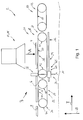
- Fig.1 shows an embodiment of a conveying device 2 according to the invention (hereinafter also abbreviated as conveying device 2) for conveying workpieces 4,6,8 in particular Printed circuit boards, in the conveying direction T along a conveyor line 10th
- the conveyor device 2 or the conveyor line 10 is part of a production line (not shown) and thus leads the processing stations 12, the respective workpieces 2,4,6 for processing.
- a processing station 12 also includes the functions of a testing station 14 for the workpiece inspection.
- processing station 12 is used to test printed circuit boards with their particular characteristics as a wafer 4,6,8, wherein the test of a wafer 4,6,8, in particular in this embodiment of the invention by an optical test system 16.
- the data recorded thereby are evaluated by an evaluation device in accordance with the specifications in order to ascertain the quality of the workpiece 4, 6, 8 or wafer 4, 6, 8.
- the aforementioned components without reference numerals are not shown.
- the conveyor 2 is equipped with first conveyor means 18 for workpiece conveyance along a first section 20 of the conveyor section 10 and second conveyor means 22 for workpiece conveyance along a second section 24 of the conveyor section 10, which is the first section 20 upstream in the conveying direction T to the first Subsection 20 to supply workpieces 4,6,8.
- the conveyor 2 is characterized in that it has separating means 26 which serve to at least partially along the first section 20 of the conveying path 10 to separate a workpiece 2,4 from a directly downstream in the conveying direction T workpiece 4,6.
- the separation means 26 a spacer 28 which in the conveying direction T between an initial position 30 and an end position 32 spaced apart in the conveying direction T in such a way and controllable by control means (not shown) with which this is technically connected, that the spacer 28 by passing the initial position 30 through the workpiece 4, 6.8 changes into an active mode, in which it follows the workpiece 4, 6, 8 downstream in the conveying direction T, forming a minimum distance between the workpiece 4, 6 and the downstream workpiece 6, 8, and reaching the end position 32 in FIG changes to an inactive mode in which the spacer 28 returns to the initial position 30.
- the spacer 28 forms in this embodiment of the invention, the minimum distance purely mechanically or by its geometric dimensions by the component of the spacer 28, with which this comes to form a minimum distance in mechanical contact with the workpiece 2,4 and with this subsequent workpiece 4.6, determined by its dimension in the conveying direction T, the minimum distance.
- the aforementioned mechanical contact or a contact of a workpiece 4,6,8 takes place at least by means of a portion of the spacer (28).
- the determination of the minimum distance by the spacer 28 can also be done electronically or in a combination of electronic or mechanical spacing of the aforementioned workpieces 4,6,8.
- a contact of the workpiece 4, 6, 8 is essentially limited to the cases that slip occurs between the movement of the workpiece 4, 6, 8 in the conveying direction T and the actual workpiece conveying, in particular by the first conveying means or in the conveying direction T the workpiece 4,6,8 subsequent workpiece 6,8 approaches and threatens a collision between the respective workpieces 4,6,8.
- the spacer is guided by a linear guide 29 for a movement in the conveying direction (T) between an initial position 30 and an end position 32.
- This type of tracking of the spacer 28 may therefore be based on a sensor (not shown), which detects the individual positions of the spacer 28 and workpiece 4,6,8 and the control means (not shown) controls the movement of the spacer 28 accordingly.
- the conveying device 2 provides that the workpiece conveying takes place intermittently at least by the first conveying means 18, wherein the conveying of the workpiece 4, 6, 8 by the first conveying means 18 upon reaching a rest position (workpiece 4 is located in FIG Fig. 1 in such a), in which the inspection station 16 checks the workpiece 4, 6, 8 in a processing period, the conveying of the workpiece 4, 6, 8 in the conveying direction T during the Processing period suspended.
- the conveying device 2 provides that the first conveying means 18 as well as the second conveying means 22 are each designed in the manner of a continuous conveyor 34, 36 and in each case have at least one, in particular endless, conveyor belt 38, 40.
- a conveying movement for the workpiece conveying takes place in each of the conveyor belts 38, 40 in each case by a circulation movement about two axially parallel rollers 42, 44, 46, spaced apart in the conveying direction T.
- the first section 20 of the conveyor section 10 is downstream of a third conveyor line 50 of the conveyor section 10 in the conveying direction T, which workpieces 4,6,8 are supplied via the first section 20.
- the conveyor 2 provides third conveyor means 52 for workpiece conveyance along the third section 50 of the conveyor section 10, which is directly downstream of the first section 20 in the conveying direction T, which feeds the first section 20 workpieces 4,6,8 to their further workpiece support.
- the conveying device 2 is further characterized in that the first conveying means 18 and the second conveying means 24 as well as the third conveying means 54 each have a first endless conveyor belt 54,56,58 and a second endless conveyor belt 60,62,64 spaced transversely to the conveying direction T. have, whose respective circumferential movement of the conveyor belts 64,56,58,60,62,64 for workpiece conveyance by the respective funding means 18,22,52 respectively matched or synchronized with each other.
- Fig. 7 illustrated schematically.
- the spacer 28 is arranged in its active mode as well as in the inactive mode transversely to the conveying direction T between the first and the second conveyor belt 54, 56 of the first conveying means 18 and equidistant from them.
- the separation means 26 electrically operated drive means (not shown) for generating a movement of the spacer 28 between the initial position 30 and end position 32 to track the spacer 28 the respective workpiece 4,6,8 by a corresponding drive movement and after Reaching the end position 32 to move back to the initial position 30.
- the drive means are signal-technically connected to the control means (not shown) of the conveyor 2 which, among other things, control the movement of the spacer 28.
- the control means are used to determine whether a workpiece has passed the initial position 30 for the spacer 28 or its end position 32.
- the control means sensors, with which it is connected control or signaling technology. The sensors can serve, among other things, a result of the Passing workpieces (4,6,8) at aforementioned positions (30,32) to sense or capture, whereupon the control means are able to initiate appropriate actions or control components accordingly.
- the aforementioned components without reference numerals are not shown in the figures.
- the invention provides that the separation means 26 have at least one actuator 65, the spacer 28 in the active mode to form a minimum distance between the Workpiece 4, 6, 8 and the workpiece 6, 8 following in the conveying direction T are at least partially moved into the movement path B of the workpiece 4, 6, 8 and upon reaching the end position 32 in the vertical direction 68 for a movement of the spacer 28 from the end position 32 moved out into the initial position 30 from the movement path B of the workpiece 4,6,8.
- the actuator 65 at least one lifting / lowering device 66 for the spacer 28, which raise the spacer 28 in the active mode by a lifting movement to form a minimum distance of the workpieces 4,6,8 in the vertical direction 68, and upon reaching the end position 32nd in the vertical direction 68 for a movement of the spacer 28 from the end position 32 to the initial position 30 from the movement path B in a collision-free area, in particular below the subsequent workpiece 6,8 lower.
- the spacer 28 is prevented from colliding with a workpiece 4, 6, 8.
- Fig. 1 shows the conveyor 2 in one first operating phase in which the test station 16 along the first section 20 of the conveyor section 10 supplied workpiece 4 is subjected to a test.
- Fig. 1 the spacer 28 is shown in an active mode, in which the spacer 28 in the conveying direction T the workpiece 4 is arranged directly downstream and upstream of this and a workpiece 4 in the conveying direction T directly downstream workpiece 6.
- the spacer 28 is disposed between the aforementioned workpieces 4,6,8 without contact to these.
- the spacer 28 has been raised by the lifting / lowering device 66 after the workpiece concerned 2,4,6 has passed the initial position 30 for the spacer 28.
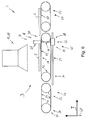
- Fig. 2 is the conveyor 2 from Fig. 1 presented in a second phase of operation.
- the workpiece is 4,6,8 promoted in the conveying direction T by the first conveying means 18 and the third conveying path 52, respectively.
- the spacer 28 moves towards its end position 32.
- the workpiece 6, 8 directly following the workpiece 4, 6, 8 in the conveying direction T is fed to the first section 20 via the second section 24 and by means of the first conveyor 18 along the first section 20 promoted.
- the workpiece 4,6,8 reaches a rest position and the spacer 28 its end position 32, in which it is lowered by the lifting / lowering device 66 in the vertical direction 68 and returned to its initial position 30.
- This process is in Fig. 3 and Fig.
- Fig. 6 shows a sixth operating state of the conveyor 2, the in Fig. 1 is similar to the first operating state shown.
- the invention is also suitable that its components described above can also be used in a redundant manner.
Landscapes
- Engineering & Computer Science (AREA)
- Mechanical Engineering (AREA)
- Manufacturing & Machinery (AREA)
- Microelectronics & Electronic Packaging (AREA)
- Control Of Conveyors (AREA)
- Attitude Control For Articles On Conveyors (AREA)
Priority Applications (3)
| Application Number | Priority Date | Filing Date | Title |
|---|---|---|---|
| US14/163,211 US9233802B2 (en) | 2013-10-31 | 2014-01-24 | Conveyor device for the conveyance of workpieces, specifically of circuit boards, in the conveyance direction along a conveyance path |
| PCT/EP2014/002918 WO2015062729A1 (fr) | 2013-10-31 | 2014-10-30 | Dispositif de transport pour transporter des pièces, en particulier des cartes de circuits imprimés, dans une direction de transport le long d'un trajet de transport |
| CN201480058150.6A CN105683066A (zh) | 2013-10-31 | 2014-10-30 | 用于沿输送方向沿着输送路径输送工件,特别是电路板的输送设备 |
Applications Claiming Priority (1)
| Application Number | Priority Date | Filing Date | Title |
|---|---|---|---|
| DE201310112056 DE102013112056A1 (de) | 2013-10-31 | 2013-10-31 | Fördervorrichtung zur Förderung von Werkstücken, insbesondere Leiterplatten, in Förderrichtung entlang einer Förderstrecke |
Publications (1)
| Publication Number | Publication Date |
|---|---|
| EP2868601A1 true EP2868601A1 (fr) | 2015-05-06 |
Family
ID=49724932
Family Applications (1)
| Application Number | Title | Priority Date | Filing Date |
|---|---|---|---|
| EP20130005442 Withdrawn EP2868601A1 (fr) | 2013-10-31 | 2013-11-20 | Dispositif de transport destiné au transport de pièces, notamment de cartes de circuit imprimé, dans une direction de convoyage le long d'une ligne de convoyage |
Country Status (5)
| Country | Link |
|---|---|
| US (1) | US9233802B2 (fr) |
| EP (1) | EP2868601A1 (fr) |
| CN (1) | CN105683066A (fr) |
| DE (1) | DE102013112056A1 (fr) |
| WO (1) | WO2015062729A1 (fr) |
Cited By (2)
| Publication number | Priority date | Publication date | Assignee | Title |
|---|---|---|---|---|
| EP3219649A1 (fr) * | 2016-03-15 | 2017-09-20 | MULTIVAC Sepp Haggenmüller SE & Co. KG | Dispositif de transport pour coques |
| WO2018054402A1 (fr) * | 2015-09-21 | 2018-03-29 | Viscom Ag | Procédé de détection de pièce et dispositif de détection |
Families Citing this family (8)
| Publication number | Priority date | Publication date | Assignee | Title |
|---|---|---|---|---|
| US10556356B2 (en) * | 2012-04-26 | 2020-02-11 | Sharper Tools, Inc. | Systems and methods for performing a task on a material, or locating the position of a device relative to the surface of the material |
| JP5861041B2 (ja) * | 2013-03-07 | 2016-02-16 | パナソニックIpマネジメント株式会社 | 基板搬送機構および部品実装用装置 |
| JP6695026B2 (ja) * | 2016-02-08 | 2020-05-20 | パナソニックIpマネジメント株式会社 | 部品実装方法および部品実装装置 |
| TWI609825B (zh) * | 2016-12-09 | 2018-01-01 | Chipmos Technologies Inc. | 捲帶輸送裝置 |
| IT201700075065A1 (it) * | 2017-07-04 | 2019-01-04 | Manz Italy Srl | Apparato per produrre dispositivi di accumulo di energia elettrica |
| CN110282394A (zh) * | 2019-06-15 | 2019-09-27 | 泰州市旺灵绝缘材料厂 | 一种电路板传送装置 |
| CN113120578A (zh) * | 2020-01-15 | 2021-07-16 | 顺丰科技有限公司 | 传输装置、传输机构控制方法及存储介质 |
| CN113677094B (zh) * | 2021-07-26 | 2022-08-23 | 江西旭昇电子有限公司 | 一种pcb板水平电镀入料装置及入料方法 |
Citations (7)
| Publication number | Priority date | Publication date | Assignee | Title |
|---|---|---|---|---|
| GB2045712A (en) * | 1979-03-29 | 1980-11-05 | Bruno & Co Alisyncro | Apparatus for feeding products to a work station |
| GB2090804A (en) * | 1981-01-08 | 1982-07-21 | Sig Schweiz Industrieges | Grouping articles before packaging |
| DE9306597U1 (de) * | 1993-05-04 | 1993-07-29 | Ostma Maschinenbau GmbH, 53909 Zülpich | Vorrichtung für die Abgabe von Produkten an eine Aufnahmestation |
| WO1996021576A1 (fr) * | 1995-01-13 | 1996-07-18 | Groenbjerg Ib | Procede et installation destines au transport de piles d'ebauches d'etiquettes sous une forme decoupee sur un transporteur a accumulation |
| WO2006024460A1 (fr) * | 2004-09-02 | 2006-03-09 | Krones Ag | Dispositif de groupage de marchandises de detail |
| DE102011075174A1 (de) * | 2011-05-03 | 2012-11-08 | Robert Bosch Gmbh | Transfereinrichtung für Gegenstände |
| WO2013109900A2 (fr) * | 2012-01-18 | 2013-07-25 | Douglas Machine Inc. | Appareil, système & procédés de comptage d'objets |
Family Cites Families (5)
| Publication number | Priority date | Publication date | Assignee | Title |
|---|---|---|---|---|
| US4040512A (en) * | 1976-01-12 | 1977-08-09 | Ness Warren C | Method of and means for indexing articles |
| DE2853483C2 (de) * | 1978-12-12 | 1985-08-29 | geb. Kramer Elfriede 6920 Sinsheim Gebhardt | Stauförderer für Stückgut |
| US5073342A (en) * | 1989-01-05 | 1991-12-17 | Eastman Kodak Company | Reciprocating transfer mechanism |
| DE19645760A1 (de) * | 1996-11-06 | 1998-05-07 | Schmid Gmbh & Co Geb | Verfahren und Vorrichtung zur Erzeugung eines definierten Stroms horizontal geführter Leiterplatten |
| JP3915923B2 (ja) * | 2003-11-28 | 2007-05-16 | ソニー株式会社 | ワークの搬送装置 |
-
2013
- 2013-10-31 DE DE201310112056 patent/DE102013112056A1/de active Pending
- 2013-11-20 EP EP20130005442 patent/EP2868601A1/fr not_active Withdrawn
-
2014
- 2014-01-24 US US14/163,211 patent/US9233802B2/en active Active
- 2014-10-30 CN CN201480058150.6A patent/CN105683066A/zh active Pending
- 2014-10-30 WO PCT/EP2014/002918 patent/WO2015062729A1/fr not_active Ceased
Patent Citations (7)
| Publication number | Priority date | Publication date | Assignee | Title |
|---|---|---|---|---|
| GB2045712A (en) * | 1979-03-29 | 1980-11-05 | Bruno & Co Alisyncro | Apparatus for feeding products to a work station |
| GB2090804A (en) * | 1981-01-08 | 1982-07-21 | Sig Schweiz Industrieges | Grouping articles before packaging |
| DE9306597U1 (de) * | 1993-05-04 | 1993-07-29 | Ostma Maschinenbau GmbH, 53909 Zülpich | Vorrichtung für die Abgabe von Produkten an eine Aufnahmestation |
| WO1996021576A1 (fr) * | 1995-01-13 | 1996-07-18 | Groenbjerg Ib | Procede et installation destines au transport de piles d'ebauches d'etiquettes sous une forme decoupee sur un transporteur a accumulation |
| WO2006024460A1 (fr) * | 2004-09-02 | 2006-03-09 | Krones Ag | Dispositif de groupage de marchandises de detail |
| DE102011075174A1 (de) * | 2011-05-03 | 2012-11-08 | Robert Bosch Gmbh | Transfereinrichtung für Gegenstände |
| WO2013109900A2 (fr) * | 2012-01-18 | 2013-07-25 | Douglas Machine Inc. | Appareil, système & procédés de comptage d'objets |
Cited By (2)
| Publication number | Priority date | Publication date | Assignee | Title |
|---|---|---|---|---|
| WO2018054402A1 (fr) * | 2015-09-21 | 2018-03-29 | Viscom Ag | Procédé de détection de pièce et dispositif de détection |
| EP3219649A1 (fr) * | 2016-03-15 | 2017-09-20 | MULTIVAC Sepp Haggenmüller SE & Co. KG | Dispositif de transport pour coques |
Also Published As
| Publication number | Publication date |
|---|---|
| WO2015062729A1 (fr) | 2015-05-07 |
| US9233802B2 (en) | 2016-01-12 |
| DE102013112056A1 (de) | 2015-04-30 |
| US20150114796A1 (en) | 2015-04-30 |
| CN105683066A (zh) | 2016-06-15 |
Similar Documents
| Publication | Publication Date | Title |
|---|---|---|
| EP2868601A1 (fr) | Dispositif de transport destiné au transport de pièces, notamment de cartes de circuit imprimé, dans une direction de convoyage le long d'une ligne de convoyage | |
| DE102007014876B4 (de) | Transportsystem | |
| DE112011102749B4 (de) | Zubringförderer, Schaltungssubstratbearbeitungsmaschine und Schaltungssubstratbearbeitungssystem | |
| EP2634100A1 (fr) | Machine de verrouillage de coques et procédé destiné au transport de coques | |
| EP3853156A1 (fr) | Procédé et dispositif d'acheminement de produits d'un premier processus vers un second processus dans une installation d'emballage | |
| EP3202671A2 (fr) | Machine d'emballage par emboutissage | |
| DE102012009061A1 (de) | Bearbeitungsanlage für Baueinheiten | |
| EP2073620A1 (fr) | Dispositif de transport de substrat pour un automate d'implantation | |
| EP3354121B1 (fr) | Procédé de détection de pièce et dispositif de détection | |
| EP3328765B1 (fr) | Dispositif de transport | |
| DE102016124384A1 (de) | Verfahren und Vorrichtung zum Fügen von Werkstücken | |
| DE102014202087A1 (de) | Vorrichtung und Verfahren zum Aufteilen eines Stroms stückiger Produkte | |
| EP1050388A2 (fr) | Machine pour l'usinage des arêtes avec chaine transporteuse de pièces | |
| EP3749521B1 (fr) | Dispositif de sérigraphie pour une installation de rouleau à rouleau | |
| DE102019209923B4 (de) | Verfahren zum Transportieren von Werkstückteilen | |
| DE102006049647A1 (de) | Arbeitsstation zur Verbindung von Karosserieteilen eines Kraftfahrzeugs, Fertigungsstraße mit einer solchen Arbeitsstation sowie Verfahren zum Zustellen/Wechseln von Spannrahmen in einer Arbeitsstation | |
| WO2012048771A1 (fr) | Machine de traitement, en particulier pour l'usinage et/ou l'inspection de substrats | |
| EP4161766B1 (fr) | Procédé et appareil pour recouvrir des boîtes | |
| EP2452904B1 (fr) | Dispositif de transport de piles de documents, notamment de documents de sécurité, vers des stations de reliure | |
| DE102022114378B3 (de) | Hub-Senk-Fördersystem und Verfahren zum Betreiben eines Hub-Senk-Fördersystems | |
| DE112018006059T5 (de) | Gerät und verfahren zum selektiven löten mit synchroner bewegung | |
| DE102010001899A1 (de) | Vorrichtung und Verfahren zum Binden von Stapeln von Lagen, insbesondere für die Herstellung von sicherheitsrelevanten Dokumenten | |
| EP4129870B1 (fr) | Dispositif modulaire d'aiguillage permettant de stocker de manière intermédiaire des porte-pièces pour un système de transport linéaire | |
| EP1862046B1 (fr) | Systeme de transport lineaire et procede de transport tres precis de petits composants | |
| DE102013217142A1 (de) | Transportsystem |
Legal Events
| Date | Code | Title | Description |
|---|---|---|---|
| PUAI | Public reference made under article 153(3) epc to a published international application that has entered the european phase |
Free format text: ORIGINAL CODE: 0009012 |
|
| 17P | Request for examination filed |
Effective date: 20131120 |
|
| AK | Designated contracting states |
Kind code of ref document: A1 Designated state(s): AL AT BE BG CH CY CZ DE DK EE ES FI FR GB GR HR HU IE IS IT LI LT LU LV MC MK MT NL NO PL PT RO RS SE SI SK SM TR |
|
| AX | Request for extension of the european patent |
Extension state: BA ME |
|
| R17P | Request for examination filed (corrected) |
Effective date: 20151019 |
|
| RBV | Designated contracting states (corrected) |
Designated state(s): AL AT BE BG CH CY CZ DE DK EE ES FI FR GB GR HR HU IE IS IT LI LT LU LV MC MK MT NL NO PL PT RO RS SE SI SK SM TR |
|
| 17Q | First examination report despatched |
Effective date: 20160125 |
|
| STAA | Information on the status of an ep patent application or granted ep patent |
Free format text: STATUS: THE APPLICATION HAS BEEN WITHDRAWN |
|
| 18W | Application withdrawn |
Effective date: 20160725 |