EP2634100A1 - Machine de verrouillage de coques et procédé destiné au transport de coques - Google Patents
Machine de verrouillage de coques et procédé destiné au transport de coques Download PDFInfo
- Publication number
- EP2634100A1 EP2634100A1 EP13000840.2A EP13000840A EP2634100A1 EP 2634100 A1 EP2634100 A1 EP 2634100A1 EP 13000840 A EP13000840 A EP 13000840A EP 2634100 A1 EP2634100 A1 EP 2634100A1
- Authority
- EP
- European Patent Office
- Prior art keywords
- along
- transport
- trays
- path
- drivers
- Prior art date
- Legal status (The legal status is an assumption and is not a legal conclusion. Google has not performed a legal analysis and makes no representation as to the accuracy of the status listed.)
- Granted
Links
Images


Classifications
-
- B—PERFORMING OPERATIONS; TRANSPORTING
- B65—CONVEYING; PACKING; STORING; HANDLING THIN OR FILAMENTARY MATERIAL
- B65B—MACHINES, APPARATUS OR DEVICES FOR, OR METHODS OF, PACKAGING ARTICLES OR MATERIALS; UNPACKING
- B65B35/00—Supplying, feeding, arranging or orientating articles to be packaged
-
- B—PERFORMING OPERATIONS; TRANSPORTING
- B65—CONVEYING; PACKING; STORING; HANDLING THIN OR FILAMENTARY MATERIAL
- B65B—MACHINES, APPARATUS OR DEVICES FOR, OR METHODS OF, PACKAGING ARTICLES OR MATERIALS; UNPACKING
- B65B43/00—Forming, feeding, opening or setting-up containers or receptacles in association with packaging
- B65B43/42—Feeding or positioning bags, boxes, or cartons in the distended, opened, or set-up state; Feeding preformed rigid containers, e.g. tins, capsules, glass tubes, glasses, to the packaging position; Locating containers or receptacles at the filling position; Supporting containers or receptacles during the filling operation
- B65B43/52—Feeding or positioning bags, boxes, or cartons in the distended, opened, or set-up state; Feeding preformed rigid containers, e.g. tins, capsules, glass tubes, glasses, to the packaging position; Locating containers or receptacles at the filling position; Supporting containers or receptacles during the filling operation using roller-ways or endless conveyors
-
- B—PERFORMING OPERATIONS; TRANSPORTING
- B65—CONVEYING; PACKING; STORING; HANDLING THIN OR FILAMENTARY MATERIAL
- B65B—MACHINES, APPARATUS OR DEVICES FOR, OR METHODS OF, PACKAGING ARTICLES OR MATERIALS; UNPACKING
- B65B57/00—Automatic control, checking, warning, or safety devices
- B65B57/02—Automatic control, checking, warning, or safety devices responsive to absence, presence, abnormal feed, or misplacement of binding or wrapping material, containers, or packages
- B65B57/04—Automatic control, checking, warning, or safety devices responsive to absence, presence, abnormal feed, or misplacement of binding or wrapping material, containers, or packages and operating to control, or to stop, the feed of such material, containers, or packages
-
- B—PERFORMING OPERATIONS; TRANSPORTING
- B65—CONVEYING; PACKING; STORING; HANDLING THIN OR FILAMENTARY MATERIAL
- B65B—MACHINES, APPARATUS OR DEVICES FOR, OR METHODS OF, PACKAGING ARTICLES OR MATERIALS; UNPACKING
- B65B7/00—Closing containers or receptacles after filling
- B65B7/16—Closing semi-rigid or rigid containers or receptacles not deformed by, or not taking-up shape of, contents, e.g. boxes or cartons
- B65B7/162—Closing semi-rigid or rigid containers or receptacles not deformed by, or not taking-up shape of, contents, e.g. boxes or cartons by feeding web material to securing means
- B65B7/164—Securing by heat-sealing
Definitions
- the invention relates to a tray sealing machine with a sealing station according to the preamble of claim 1, and to a method for transporting trays by means of a transport system to, in and / or from a tray sealing machine which seals the trays with a cover film.
- trays are generally transported by means of a transport system up to a sealing station.
- the shells previously filled with a product are sealed by means of a cover film and thus sealed.
- the trays may be previously evacuated and / or gassed with a replacement gas or gas mixture.
- a gripper system is often used, as for example from the DE 10 2010 027 211.6 evident.
- the shells are on a transport route and are detected there by carriers and transported forward.
- These drivers are often transverse rods extending across the transport path and each being clamped at their two ends in a transport chain. As a result, they necessarily have a constant distance from each other, which is greater than the length of a shell in the transport direction.
- Circulating transfer systems for transporting products, but not for use in a tray sealing machine are known from WO 00/48908 A1 , of the DE 10 2009 003 080 A1 or the DE 10 2010 028 333 A1 known.
- the object of the present invention is to improve a tray sealing machine and a method for transporting trays in terms of their efficiency.
- the tray sealing machine is characterized in that the carriers configured to take along at least one tray are movable independently of one another along the carrier path.
- any two drivers no longer necessarily have a constant distance from each other and the same speed. Rather, the distances and speeds between any, especially adjacent drivers may differ. Surprisingly, this significantly increases the efficiency of the tray sealing machine. Because this way, it is possible, for example, even without the use of elaborately synchronized conveyor belts to vary the distances of the shells along their transport path to adjust these distances, for example, along the transport route changing requirements. For example, the trays could be given a slower speed along a fill line to be better filled while being quickly transported to a sealing station.
- the variable distances between adjacent drivers make it possible to adjust the distances between the shells particularly well to the dimensions of a sealing tool.
- each driver with an individual velocity profile is movable along the driver track to further enhance the flexibility of the tray sealer application.
- the tray closure machine's transport system can respond to irregularly arriving trays and even create a regular array of trays from irregularly arrived trays.
- the driving track will have a transport section for the shells associated transport section and a return section. It is favorable if the drivers are movable on the return section at a higher speed, at least at a higher average speed, than on the transport section. This makes it possible to quickly return the released after the transport of a shell driver back to the starting point of the transport section, so that a total of a smaller number of carriers is needed.
- At least one linear motor for driving the drivers is provided along the driving path.
- a linear motor is known in practice. He has a sequence of electromagnets along the endless, ie closed Mit Congressbahn are arranged.
- wheels, airbags or an electromagnetically generated floating effect could be used.
- At least one position sensor for detecting the position of a shell and / or the position of a driver is provided. Such a position sensor further enhances the efficiency of the tray sealing machine. By means of the signal of the position sensor can be ensured that a shell is reliably detected by a driver, and that even with irregularly arriving trays in each case a driver is available at a suitable time.
- a buffer section for buffering a plurality of shells can be provided along the transport path.
- Such a buffer section is characterized in that the shells have a lower speed there on average and / or have smaller distances from one another.
- the buffer section allows subsequent stations, such as the sealing station of the tray sealing machine, to be supplied as evenly as possible with a stream of trays so as to ensure uniform operation of the tray closing machine.
- the transport system has not one but two, three or generally several tracks for transporting a plurality of juxtaposed tracks of trays. Compared to a single-lane design of the tray sealer, this increases throughput, i. the number of shells transportable per unit of time along a particular section of track.
- the transport system has multiple tracks, it is possible that the carriers of different tracks are independently movable. This makes it possible to detect also irregularly arriving on adjacent tracks trays and to transport on.
- adjacent carriers of different tracks can be coupled in sections along the transport route in their speed.
- this coupling of speeds could occur If the carriers have taken exactly the same position along the transport route, so that the trays covered by them lie exactly next to each other. In this way, the shells can be processed particularly well, for example by a sealing tool.
- the drivers are each movably mounted on a carriage movable along the carrier path relative to this carriage. This makes it possible to remove the drivers from the area around a shell closing sealing tools, so that the sealing tools can form a hermetically sealed sealing chamber, without interfering with the driver.
- the driver could be provided pivotably and / or translationally movable on the carriage. For example, it could simply be moved horizontally and transversely to the transport direction of the shells to the outside. It would also be possible that the driver for this purpose has a variable length and is constructed, for example, telescopic.
- the invention also relates to a method for transporting trays by means of a transport system.
- the carriers are moved independently along a Mitauerbahn the transport system in this method to allow the above-mentioned advantages.
- the carriers are preferably moved faster along a return section of the transport system than along a transport section of the transport system, and that the trays can optionally be transported along the transport route not only in one lane but in several adjacent lanes.
- these tracks will be arranged parallel to each other. It is possible in particular that adjacent carriers of different tracks are moved in sections along the transport route at the same speed.
- At least some carriers are respectively mounted on a carriage which is movable along the carrier path, namely movable relative to this carriage, so that they can be moved out of the area of this sealing tool before closing a sealing tool.
- FIG. 1 shows a schematic representation of a Schalenversch separatemaschine invention 1 with a sealing station 2, in the shells 3, in particular plastic trays, can be closed with a cover sheet 4.
- the cover film 4 is unrolled from a film roll 5 and guided over a deflection roller 6 in the sealing station 2.
- a further deflecting roller 7 deflects the remaining film grid of the cover film 4 onto a residual film winder 8.
- the sealing station 2 has in the usual way a lower tool 9 and an upper tool 10. These tools 9, 10 of the sealing station 2 are in FIG. 1 shown in an open position. However, they may be transferred to a closed position in which they form between them a hermetically sealed sealing chamber 11 in which the trays 3 filled with a product 12 can be evacuated and / or fumigated before being sealed.
- the tray sealing machine 1 has a transport path 13 along which the trays 3 are transported in a transport direction T to the sealing station 2, through the sealing station 2 and from the sealing station 2.
- the transport path 13 may be formed, for example in the form of a support or sliding plane on which rest the shells 3.
- the trained as a support transport section 13 has a slot or an interruption, so that a below the Transport path 13 arranged transport system 14, the shells 3 detect and can transport along the transport path 13.
- the transport system 14 may laterally surround the transport path 13.
- the transport system 14 has an endless carrier track 15.
- This carrier track 15 in turn has a first, straight, the transport path 13 associated and located directly below this transport section 13 transport section 16, and also a rectilinear, located below or next to the transport section 16 return section 17 and two the two aforementioned sections 16, 17 connecting , Curved connecting portions 18, 19.
- On the driving track 15 is a finite number of carriages 20 which are movable along the driving path 15.
- Each carriage 20 has a driver 21, which is designed with respect to its size and stability to take away at least one shell 3 and protrudes in the present embodiment for this purpose from below through a slot in the transport path 13 so that the upward on the transport path 13 also protruding portion of the driver 21 can detect and take a shell 3.
- the driver 21 may be designed for this purpose as a rod, as a plate or as a bracket.
- the driving track 15 is formed as a whole linear motor 22.
- the Mitauerbahn 15 forms the stationary part of the linear motor 22, whose movable part or runners are formed by the carriage 20.
- the Mitauerbahn 15 is divided into fine sections 23, which are shown for clarity only in a short range.
- a variable magnetic field can be applied to the individual sections 23 in such a way that this magnetic field moves the carriages 20 along the carrier track 15.
- located on the transport section 16 carriage 20 and driver 21 move in the transport direction T of the shells, while they move on the return section 17 in the reverse direction.
- the sections 23 of the linear motor 22 are configured so that they can be controlled individually by the controller 24. This makes it possible according to the invention, the individual Driver 21 independently, in particular independently of the respective adjacent carriages and carriers 21 to move along the driving path 15. Thus, it is even possible that each driver 21 along the carrier track 15 receives its own, individual speed profile.
- Position sensors 25, 26, for example in the form of light barriers or cameras, are used to detect a position of a shell 3 or a driver 21.
- a first position sensor 25 is arranged at the beginning of the transport path 13 to there the position and the presence of a shell 3 to capture. The position sensor 25 may be located above, below or next to the transport path 13.
- a second position sensor 26 is arranged at the end of the return section 17 of the carrier track 15 in order to detect there the presence and the position of a carriage 20 with a driver 21 and / or the condition and in particular possible defects of the driver 21.
- the transport system 14 may have its own position detection system for real-time detection of the position of each individual carriage 20.
- trays 3 are made available to the transport system 14, for example manually or by a destacker.
- the arrangement of the shells 3 may be irregular in the insertion region 28.
- the position of each individual shell 3 is detected by the position sensor 25 and transmitted to the controller 24. This ensures by appropriate control of the linear motor 22 of the carrier track 15 that each tray 3, a carriage 20 is provided with a driver 21. This driver 21 detects the respective shell 3 and ensures their transport along the transport path 13.
- the empty shells 3 reach along the transport path 13 to a filling line 29.
- the shells 3 are filled with a product 12. This filling can be done automatically or manually.
- the individual control of the driver 21 allows that the driver 21 and the shells 3 covered by them the Reach equidistant filling line 29, even if they were originally used in an irregular arrangement.
- the control of the driver 21 is further carried out so that the shells 3 occupy a minimum distance from each other along the filling section 29. This reduces the likelihood that a product passes between the trays 3 on the transport path 13. In addition, the small distances between the shells 3 facilitate the filling of the shells.
- the filling section 29 may be designed for this purpose as a buffer section of the transport path 13, which is designed to buffer a variable number of shells 3. However, the buffer section may also be formed separately from the filling section 29. Along the filling path 29, the speed of the carriage 20 and thus the driver 21 and the shells 3 is reduced.
- the shells 3 are again accelerated to a higher speed and brought to mutual distances A from each other, which correspond to the distances of the shells 3 in a sealing tool 31 of the sealing station 2.
- the speed of the drivers 21 and the shells 3 along the portion 30 can be controlled precisely so that a suitable group of shells 3 enters the sealing station 2 immediately after the opening of the lower and upper tool 9, 10 of the sealing station 2.
- the carriages 20 and thus the trays 3 are stopped. If necessary, carriages 20 are moved back out of the sealing station 2 or the drivers 21 are removed from the region of the sealing station 2. Lower and upper tool 9, 10 of the sealing station 2 close.
- the sealing chamber 11 is evacuated and, if appropriate, fumigated before the sealing tool 31 seals the cover film 4 to the shells 3.
- the closed trays 3 are transported out of the sealing station 2 and removed.
- the carriage 20 and catch 21 freed from the shells 3 are accelerated and moved along the return section 17 at a higher speed than on the transport section 16 until the end of the return section 17. There, the free and available carriers 21 accumulate in a storage area 32.
- the position of the foremost carrier 21 is monitored by means of the position sensor 26. As soon as the position sensor 25 gives a corresponding signal, the foremost driver 21 is accelerated via the connection section 19 in order to detect a new shell 3.
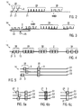
- FIG. 2 shows the embodiment according to FIG. 1 once again in a more abstract form.
- the empty trays 3 are placed on the transport path 13 and detected there by free carriers 21.
- the buffer section 29 the distances between adjacent shells 3 are minimized in order to be able to buffer as many shells 3 there as possible over the shortest possible distance.
- the trays 3 are accelerated and their distances are adapted to the dimensions of the sealing tool 31.
- FIG. 3 In a likewise abstracted form, a variant of the transport system 14 is shown. It differs from the first exemplary embodiment in that the trays 3 in the insertion region 28 are taken over by an upstream conveyor belt 33 onto the transport path 13. The position sensor 25 detects the position of the possibly irregularly arriving shells. 3
- FIG. 4 shows an equally abstract representation of another variant of the transport system 14, but this time in plan view.
- the shells 3 are placed on the transport path 13 and detected by the drivers 21.
- the buffer area 29 the shells 3 are buffered and can be optionally filled there.
- the grouping section 30 the distances between the shells 3 increase.
- groups of three shells each are formed there, which are fed together as a group to the sealing station 2.
- the sealing station 2 is configured to collectively seal a group of three trays 3 in this example.
- the transport path 13 comprises a separating section 34.
- individual control of the driver 21, the distances between adjacent shells 3 are increased on the separating section 34 in order to separate the shells from each other. This facilitates individual removal of the filled and sealed trays 3 and also individual process steps such as weighing, checking and / or labeling of the finished trays 3.
- FIG. 5 also shows in plan view and also in abstract form another embodiment of the transport system 14.
- the transport system along the transport path 13 has three adjacent tracks S1, S2, S3. Trays 3 can be transported on each of the parallel tracks S1, S2, S3.
- Trays 3 can be transported on each of the parallel tracks S1, S2, S3.
- under each of the three tracks S1 to S3 each have their own carrier track 15 with its own drivers 21 as in FIG. 1 intended.
- the trays 3 do not necessarily have to be inserted in a regular shape.
- the individual control of the driver 21 still makes it possible to move the trays 3 on the individual tracks S1 to S3 so that from a position 35 trays 3 on all three tracks S1 to S3 are directly adjacent to each other and at the same height.
- FIGS. 6a to 6c show different operating variants that result with a multi-lane transport system 14.
- FIG. 6 corresponds to the already on the basis of FIG. 5 described situation in which an irregular arrangement of shells 3 along the three tracks S1 to S3 in a regular arrangement with immediately adjacent and at the same height shells 3 is transferred. In each case, there is a shell 3 on each of the three tracks S1, S2, S3.
- FIG. 6b is a larger shell 3 ', which extends in the transverse direction over all three tracks S1 to S3, transported along the transport path 13. With such wide shells 3 ', it is sufficient if only two of the drivers 21 on the three tracks S1 to S3 on the shell 3' attack.
- FIG. 6c shows another variant.
- a shell 3 having the same dimension as originally transported.
- a further shell 3 is wider and is transported on the two other tracks S2, S3.
- With suitable stabilization of the shell 3 it is sufficient if only one of the two drivers 21 of the two tracks S2, S3 acts on the more ready shell 3 " ,
- FIG. 7 schematically shows a plan view of a further variation possibility, which lends itself to all embodiments of the invention Schalenverschdorfmaschine 1, in which due to the dimensions of the sealing station 2 in the transport direction T consecutively several shells 3 seal at the same time.
- the transport path 13 has two tracks S1, S2.
- the sealing station 2 or its sealing tool 31 are large enough to simultaneously detect and seal a group of four shells, ie in each case two shells 3 on each of the two parallel tracks S1, S2.
- the Mit supportivebahnen 15 for the carriage 20, on which the drivers 21 are mounted are in this embodiment, in each case adjacent to the two tracks S1, S2.
- the drivers 21 protrude in a transport position on the transport path 13 so that they each detect a shell 3.
- the drivers 21 are movably mounted on their associated carriage 20.
- the dogs 21 are configured to move linearly, horizontally, outward through the carriages 20 until they are completely outside the area of the sealing station 2.
- the drivers 21 are formed telescopically and can shorten their length and / or that they are pivotally mounted on the carriage 20 and can thus be removed from the area of the sealing station 2. In this way, no one of the drivers 21 obstructs the sealing tools 9, 10, if they close to form the sealing chamber 11.
- the tray sealing machine 1 according to the invention and the method according to the invention can be modified in many ways.
- the sealing station 2 prefferably has, per track S1, S2, S3, a group of lower tool 9, upper tool 10 and sealing tool 31 which can be operated independently of the other tracks.
- a separate film roll 5 and a Restfolienaufwickler 8 may be provided.
Landscapes
- Engineering & Computer Science (AREA)
- Mechanical Engineering (AREA)
- Microelectronics & Electronic Packaging (AREA)
- Closing Of Containers (AREA)
- Package Closures (AREA)
Applications Claiming Priority (1)
| Application Number | Priority Date | Filing Date | Title |
|---|---|---|---|
| DE102012004372A DE102012004372A1 (de) | 2012-03-02 | 2012-03-02 | Schalenverschließmaschine und Verfahren zum Transportieren von Schalen |
Publications (2)
| Publication Number | Publication Date |
|---|---|
| EP2634100A1 true EP2634100A1 (fr) | 2013-09-04 |
| EP2634100B1 EP2634100B1 (fr) | 2016-02-17 |
Family
ID=47750402
Family Applications (1)
| Application Number | Title | Priority Date | Filing Date |
|---|---|---|---|
| EP13000840.2A Active EP2634100B1 (fr) | 2012-03-02 | 2013-02-19 | Machine de verrouillage de coques et procédé destiné au transport de coques |
Country Status (3)
| Country | Link |
|---|---|
| US (1) | US9346576B2 (fr) |
| EP (1) | EP2634100B1 (fr) |
| DE (1) | DE102012004372A1 (fr) |
Cited By (4)
| Publication number | Priority date | Publication date | Assignee | Title |
|---|---|---|---|---|
| CN104670526A (zh) * | 2014-12-17 | 2015-06-03 | 广东立高食品有限公司 | 果馅自动化包装生产线及其包装方法 |
| WO2016091446A1 (fr) * | 2014-12-11 | 2016-06-16 | Robert Bosch Gmbh | Dispositif de transport pour machine d'emballage |
| CN111846468A (zh) * | 2019-04-30 | 2020-10-30 | 莫迪维克西普哈根牧勒股份及两合公司 | 托盘密封机和轻柔地拾起托盘的方法 |
| EP3626634B1 (fr) | 2018-09-20 | 2021-08-25 | Krones Aktiengesellschaft | Dispositif de manipulation et / ou d'emballage et procédé d'emballage des articles |
Families Citing this family (33)
| Publication number | Priority date | Publication date | Assignee | Title |
|---|---|---|---|---|
| ITMO20080063A1 (it) * | 2008-03-05 | 2009-09-06 | Inovapak Srl | Apparati e metodi per produrre contenitori |
| ITBO20130162A1 (it) * | 2013-04-12 | 2014-10-13 | Marchesini Group Spa | Metodo e sistema per sincronizzare una stazione di lavorazione di una macchina blisteratrice con l'avanzamento di un nastro blister |
| DE102013105932A1 (de) * | 2013-06-07 | 2014-12-11 | Khs Gmbh | Vorrichtung zum Abteilen von Verpackungseinheiten |
| DE102013218397B4 (de) * | 2013-09-13 | 2024-07-04 | Krones Ag | Vorrichtung und Verfahren zum Gruppieren von Behältern |
| ITTO20130858A1 (it) * | 2013-10-23 | 2015-04-24 | Cavanna Spa | Sistema e procedimento per il confezionamento di prodotti |
| CA2932911A1 (fr) * | 2013-12-06 | 2015-06-11 | R.A Jones & Co. | Appareil et procedes d'emballage a pas variable |
| DE102014106400A1 (de) | 2014-04-25 | 2015-11-12 | Weber Maschinenbau Gmbh Breidenbach | Individueller transport von lebensmittelportionen |
| ES2614468T3 (es) | 2014-12-30 | 2017-05-31 | Multivac Sepp Haggenmüller Se & Co. Kg | Máquina de envasado con un conjunto de bombas de fluido |
| ES2637746T3 (es) * | 2015-01-19 | 2017-10-16 | Cama1 S.P.A. | Una máquina embaladora con una transportadora de impulsores magnéticos |
| ITUB20152469A1 (it) * | 2015-07-24 | 2017-01-24 | Marco Verri | Apparecchiatura per la realizzazione di un prodotto, preferibilmente di un prodotto alimentare per realizzare una bevanda tramite infusione in un rispettivo liquido |
| DE102016203814B4 (de) | 2016-03-09 | 2026-01-22 | Ampack Gmbh | Vorrichtung zum Transport von Packmittel, insbesondere von Flaschen oder Bechern |
| DE102016204193A1 (de) | 2016-03-15 | 2017-09-21 | Multivac Sepp Haggenmüller Se & Co. Kg | Transportvorrichtung für Schalen |
| DE102016108002A1 (de) * | 2016-04-29 | 2017-11-02 | Weber Maschinenbau Gmbh Breidenbach | Verfahren zum Bewegen von Portionen |
| JP6155406B1 (ja) * | 2016-06-21 | 2017-06-28 | ユニ・チャーム株式会社 | 製品搬送装置 |
| US10381958B2 (en) * | 2017-09-28 | 2019-08-13 | Rockwell Automation Technologies, Inc. | Method and apparatus for commutation of drive coils in a linear drive system with independent movers |
| IT201800002805A1 (it) * | 2018-02-19 | 2019-08-19 | Makro Labelling Srl | Macchina per il trattamento di contenitori |
| GB2582184B (en) * | 2019-03-15 | 2022-03-02 | Proseal Uk Ltd | A packaging machine and method |
| EP4003887B1 (fr) | 2019-07-30 | 2025-02-12 | Anheuser-Busch InBev S.A. | Appareil de désempilage |
| ES2982363T3 (es) | 2019-07-30 | 2024-10-15 | Anheuser Busch Inbev Sa | Aparato de envasado |
| CN114502471A (zh) | 2019-07-30 | 2022-05-13 | 安海斯-布希英博有限公司 | 物品拾取和处理设备 |
| CN114466796B (zh) | 2019-07-30 | 2024-04-16 | 安海斯-布希英博有限公司 | 用于二级包装的包装设备 |
| CN114845937A (zh) | 2019-07-30 | 2022-08-02 | 安海斯-布希英博有限公司 | 用于二次包装的成形工具 |
| IT201900013965A1 (it) * | 2019-08-05 | 2021-02-05 | Ima Spa | Macchina per la realizzazione di capsule. |
| JP7388983B2 (ja) * | 2020-06-22 | 2023-11-29 | 株式会社京都製作所 | 箱詰装置 |
| DE102021105098A1 (de) | 2021-03-03 | 2022-09-08 | Provisur Technologies, Inc. | Nahrungsmittelverarbeitungsanlage |
| DE102021105104A1 (de) | 2021-03-03 | 2022-09-08 | Provisur Technologies, Inc. | Bandförderer zum Fördern von Nahrungsmittelprodukten |
| EP4108600A1 (fr) * | 2021-06-25 | 2022-12-28 | MULTIVAC Sepp Haggenmüller SE & Co. KG | Machine d'emballage dotée d'un convoyeur à barre de poussée |
| DE102021122721A1 (de) * | 2021-09-02 | 2023-03-02 | Homag Gmbh | Fördervorrichtung mit unabhängig bewegbaren Nocken zur Zuführung und/oder Ausrichtung von Werkstücken |
| JP7345805B1 (ja) * | 2022-04-27 | 2023-09-19 | オリオン機械工業株式会社 | 開袋装置 |
| DE102022130581B4 (de) * | 2022-11-18 | 2024-09-12 | Vemag Maschinenbau Gmbh | Beladeeinrichtung mit einer Portioniereinheit und Betriebsverfahren |
| DE102023108041A1 (de) | 2023-03-29 | 2024-10-02 | Ampack Gmbh | Siegelvorrichtung, insbesondere Vorsiegelvorrichtung, zu einer zumindest stellenweisen Verbindung von Verschlüssen, insbesondere Deckeln, und Behältern, insbesondere Bechern, sowie entsprechendes Verfahren |
| DE102023108046A1 (de) * | 2023-03-29 | 2024-10-02 | Ampack Gmbh | Siegelvorrichtung zu einer Verbindung von Verschlüssen und Behältern, Produktionsmaschine mit einer entsprechenden Siegelvorrichtung sowie Verfahren zu einer Verbindung von Verschlüssen und Behältern |
| US12545532B2 (en) * | 2023-10-23 | 2026-02-10 | Rockwell Automation Technologies, Inc. | Persistent vehicle identification for an independent cart system |
Citations (10)
| Publication number | Priority date | Publication date | Assignee | Title |
|---|---|---|---|---|
| US3908342A (en) * | 1973-10-26 | 1975-09-30 | Fmc Corp | Heat sealing machine |
| WO2000048908A1 (fr) | 1999-02-17 | 2000-08-24 | G.D Societa' Per Azioni | Transporteur pour transporter des articles sur une machine d'emballage automatique |
| US20050256774A1 (en) * | 2004-05-17 | 2005-11-17 | Clothier Brian L | Food preparation system |
| DE102004042474A1 (de) * | 2004-09-02 | 2006-03-23 | Krones Ag | Vorrichtung zum Gruppieren von Stückgut |
| DE102008040204A1 (de) * | 2008-07-07 | 2010-01-14 | Robert Bosch Gmbh | Vorrichtung und Verfahren zum Transportieren von Produkten mit Linearantrieb |
| DE102009002606A1 (de) * | 2009-04-23 | 2010-10-28 | Robert Bosch Gmbh | Umlaufende Transportvorrichtung mit verbessertem Antriebskonzept |
| DE102009003080A1 (de) | 2009-05-13 | 2010-11-18 | Robert Bosch Gmbh | Positionserfassungsanordnung für ein umlaufendes Transfersystem |
| WO2011080514A2 (fr) * | 2009-12-29 | 2011-07-07 | Ishida Europe Limited | Procédé d'emballage d'aliment |
| DE102010028333A1 (de) | 2010-04-28 | 2011-11-03 | Robert Bosch Gmbh | Inkrementelles Multipositions-Erfassungssystem für ein umlaufendes elektromagnetisches Transfersystem |
| DE102010027211A1 (de) | 2010-07-15 | 2012-01-19 | Multivac Sepp Haggenmüller Gmbh & Co. Kg | Greifersystem für eine Schalenverschließmaschine |
Family Cites Families (20)
| Publication number | Priority date | Publication date | Assignee | Title |
|---|---|---|---|---|
| US2615377A (en) * | 1949-05-10 | 1952-10-28 | Marathon Corp | Apparatus for making sealed packages |
| DE3209595A1 (de) * | 1982-03-17 | 1983-10-06 | Benz & Hilgers Gmbh | Maschine zum abfuellen und verpacken von nahrungsmitteln |
| US4936072A (en) * | 1988-10-24 | 1990-06-26 | Fmc Corporation | Container filler and sealer with two directional flexing chain |
| FR2653406B1 (fr) * | 1989-10-20 | 1992-01-10 | Mecaplastic | Machine de conditionnement assurant la fermeture de barquettes de conditionnement ou similaires apres leur remplissage, et ce par soudure d'un film en matiere thermo-plastique. |
| IT1246205B (it) * | 1991-01-21 | 1994-11-16 | Geca Srl | Apparecchiatura per il trasporto e il raggruppamento di prodotti |
| US5385003A (en) * | 1993-09-08 | 1995-01-31 | Mahaffy & Harder Engineering Co. | Method and apparatus for moving and closing packaging trays |
| AU4781496A (en) * | 1995-03-06 | 1996-09-23 | Sig Schweizerische Industrie-Gesellschaft | Device for conveying products between different work stations |
| US5724785A (en) * | 1996-06-07 | 1998-03-10 | Riverwood International Corporation | Article packaging machine with improved overhead flight assembly |
| DE19745313A1 (de) * | 1997-10-14 | 1999-04-15 | Kammann Maschf Werner | Vorrichtung und Verfahren zum Dekorieren von Objekten |
| US6876896B1 (en) * | 1999-04-26 | 2005-04-05 | Ab Tetrapak | Variable motion system and method |
| ATE274460T1 (de) * | 2000-02-09 | 2004-09-15 | Sig Pack Systems Ag | Vorrichtung zum transportieren von produkten zwischen mindestens zwei stationen |
| US7134258B2 (en) * | 2001-12-05 | 2006-11-14 | R.A. Jones & Co. Inc. | Packaging apparatus and methods |
| EP2747257A3 (fr) * | 2002-06-05 | 2016-06-29 | Jacobs Automation, Inc. | Système de déplacement commandé |
| DE102004023473B4 (de) * | 2004-05-12 | 2006-05-24 | Multivac Sepp Haggenmüller Gmbh & Co. Kg | Verpackungsmaschine und Verfahren zum Zuführen von Behältern in einer Verpackungsmaschine |
| US20050274092A1 (en) * | 2004-06-10 | 2005-12-15 | Packaging Technologies, Inc. | Continuous motion sealer |
| GB0605468D0 (en) * | 2006-03-17 | 2006-04-26 | Ishida Europ Ltd | Tray sealing machine |
| FR2909365A1 (fr) * | 2006-12-01 | 2008-06-06 | Serac Group Soc Par Actions Si | Dispositif de transport d'objets a courroies superposees, installation et procede de transport correspondant |
| DE102007014876B4 (de) * | 2007-03-26 | 2010-04-08 | Kba-Metronic Aktiengesellschaft | Transportsystem |
| US20110072764A1 (en) * | 2009-09-30 | 2011-03-31 | Ross Industries, Inc. | Method and apparatus for sealing containers |
| US20130152516A1 (en) * | 2011-12-11 | 2013-06-20 | Michael Sammons | Apparatus for making, handling, and filling pouches |
-
2012
- 2012-03-02 DE DE102012004372A patent/DE102012004372A1/de not_active Withdrawn
-
2013
- 2013-02-19 EP EP13000840.2A patent/EP2634100B1/fr active Active
- 2013-03-01 US US13/781,910 patent/US9346576B2/en active Active
Patent Citations (10)
| Publication number | Priority date | Publication date | Assignee | Title |
|---|---|---|---|---|
| US3908342A (en) * | 1973-10-26 | 1975-09-30 | Fmc Corp | Heat sealing machine |
| WO2000048908A1 (fr) | 1999-02-17 | 2000-08-24 | G.D Societa' Per Azioni | Transporteur pour transporter des articles sur une machine d'emballage automatique |
| US20050256774A1 (en) * | 2004-05-17 | 2005-11-17 | Clothier Brian L | Food preparation system |
| DE102004042474A1 (de) * | 2004-09-02 | 2006-03-23 | Krones Ag | Vorrichtung zum Gruppieren von Stückgut |
| DE102008040204A1 (de) * | 2008-07-07 | 2010-01-14 | Robert Bosch Gmbh | Vorrichtung und Verfahren zum Transportieren von Produkten mit Linearantrieb |
| DE102009002606A1 (de) * | 2009-04-23 | 2010-10-28 | Robert Bosch Gmbh | Umlaufende Transportvorrichtung mit verbessertem Antriebskonzept |
| DE102009003080A1 (de) | 2009-05-13 | 2010-11-18 | Robert Bosch Gmbh | Positionserfassungsanordnung für ein umlaufendes Transfersystem |
| WO2011080514A2 (fr) * | 2009-12-29 | 2011-07-07 | Ishida Europe Limited | Procédé d'emballage d'aliment |
| DE102010028333A1 (de) | 2010-04-28 | 2011-11-03 | Robert Bosch Gmbh | Inkrementelles Multipositions-Erfassungssystem für ein umlaufendes elektromagnetisches Transfersystem |
| DE102010027211A1 (de) | 2010-07-15 | 2012-01-19 | Multivac Sepp Haggenmüller Gmbh & Co. Kg | Greifersystem für eine Schalenverschließmaschine |
Cited By (8)
| Publication number | Priority date | Publication date | Assignee | Title |
|---|---|---|---|---|
| WO2016091446A1 (fr) * | 2014-12-11 | 2016-06-16 | Robert Bosch Gmbh | Dispositif de transport pour machine d'emballage |
| CN107000865A (zh) * | 2014-12-11 | 2017-08-01 | 罗伯特·博世有限公司 | 用于包装机的运输装置 |
| US10087018B2 (en) | 2014-12-11 | 2018-10-02 | Robert Bosch Gmbh | Transporting apparatus for a packaging machine |
| CN104670526A (zh) * | 2014-12-17 | 2015-06-03 | 广东立高食品有限公司 | 果馅自动化包装生产线及其包装方法 |
| EP3626634B1 (fr) | 2018-09-20 | 2021-08-25 | Krones Aktiengesellschaft | Dispositif de manipulation et / ou d'emballage et procédé d'emballage des articles |
| CN111846468A (zh) * | 2019-04-30 | 2020-10-30 | 莫迪维克西普哈根牧勒股份及两合公司 | 托盘密封机和轻柔地拾起托盘的方法 |
| US11155372B2 (en) | 2019-04-30 | 2021-10-26 | Multivac Sepp Haggenmueller Se & Co. Kg | Tray sealing machine and method for gently picking up a tray |
| CN111846468B (zh) * | 2019-04-30 | 2022-01-11 | 莫迪维克西普哈根牧勒股份及两合公司 | 托盘密封机和轻柔地拾起托盘的方法 |
Also Published As
| Publication number | Publication date |
|---|---|
| US20130227914A1 (en) | 2013-09-05 |
| EP2634100B1 (fr) | 2016-02-17 |
| DE102012004372A1 (de) | 2013-09-05 |
| US9346576B2 (en) | 2016-05-24 |
Similar Documents
| Publication | Publication Date | Title |
|---|---|---|
| EP2634100B1 (fr) | Machine de verrouillage de coques et procédé destiné au transport de coques | |
| EP2792626B1 (fr) | Procédé et dispositif de regroupement | |
| DE102013218397B4 (de) | Vorrichtung und Verfahren zum Gruppieren von Behältern | |
| EP2807097B1 (fr) | Appareil et procédé pour dévier des articles, en particulier des récipients tels que des bouteilles | |
| DE102011016855B4 (de) | Verfahren und Vorrichtung zum Transportieren von Behältnissen oder Behältnisgebinden | |
| EP2500296B1 (fr) | Dispositif et procédé destinés au groupement de produits en vrac | |
| EP3597577B1 (fr) | Dispositif et procédé permettant de tamponner des articles | |
| EP3853156B1 (fr) | Procédé et dispositif d'acheminement de produits d'un premier processus vers un second processus dans une installation d'emballage | |
| EP2792623B1 (fr) | Dispositif et procédé de réalisation d'une formation prédéfinie sur un tapis de transport | |
| EP3059190A1 (fr) | Procede et dispositif destines a la distribution et au regroupement de recipients | |
| EP3877306B1 (fr) | Dispositif pour regrouper des contenants | |
| EP2032484B1 (fr) | Transporteur pneumatique pour bouteilles | |
| EP1012087B1 (fr) | Dispositif et procede pour mettre a l'ecart des objets transportes sur un transporteur | |
| EP3160878B1 (fr) | Procédé et dispositif de transport de produits fragmentés | |
| EP1169249A1 (fr) | Procede et dispositif pour transporter des produits en vrac | |
| EP1868925B1 (fr) | Dispositif d'acheminement pour machine d'emballage | |
| WO2017198772A2 (fr) | Dispositif et procédé pour la réunion, la distribution et/ou la redistribution définies d'une marchandise de détail et/ou de groupes de marchandises de détail | |
| WO2017198771A2 (fr) | Transporteur aiguilleur | |
| EP2194009B1 (fr) | Procédé et dispositif destinés au groupement d'articles | |
| DE202015104636U1 (de) | Handhabungsvorrichtung für Stückgut | |
| DE102006045479A1 (de) | Kartonierer | |
| AT501825B1 (de) | Fördersystem zum fördern und vereinzeln von teilen |
Legal Events
| Date | Code | Title | Description |
|---|---|---|---|
| PUAI | Public reference made under article 153(3) epc to a published international application that has entered the european phase |
Free format text: ORIGINAL CODE: 0009012 |
|
| AK | Designated contracting states |
Kind code of ref document: A1 Designated state(s): AL AT BE BG CH CY CZ DE DK EE ES FI FR GB GR HR HU IE IS IT LI LT LU LV MC MK MT NL NO PL PT RO RS SE SI SK SM TR |
|
| AX | Request for extension of the european patent |
Extension state: BA ME |
|
| 17P | Request for examination filed |
Effective date: 20140131 |
|
| RBV | Designated contracting states (corrected) |
Designated state(s): AL AT BE BG CH CY CZ DE DK EE ES FI FR GB GR HR HU IE IS IT LI LT LU LV MC MK MT NL NO PL PT RO RS SE SI SK SM TR |
|
| 17Q | First examination report despatched |
Effective date: 20140707 |
|
| REG | Reference to a national code |
Ref country code: DE Ref legal event code: R079 Ref document number: 502013001947 Country of ref document: DE Free format text: PREVIOUS MAIN CLASS: B65B0043520000 Ipc: B65B0007160000 |
|
| GRAP | Despatch of communication of intention to grant a patent |
Free format text: ORIGINAL CODE: EPIDOSNIGR1 |
|
| INTG | Intention to grant announced |
Effective date: 20150917 |
|
| RIC1 | Information provided on ipc code assigned before grant |
Ipc: B65B 43/52 20060101ALI20150907BHEP Ipc: B65B 7/16 20060101AFI20150907BHEP Ipc: B65G 54/02 20060101ALI20150907BHEP Ipc: B65B 35/00 20060101ALI20150907BHEP |
|
| GRAS | Grant fee paid |
Free format text: ORIGINAL CODE: EPIDOSNIGR3 |
|
| GRAA | (expected) grant |
Free format text: ORIGINAL CODE: 0009210 |
|
| AK | Designated contracting states |
Kind code of ref document: B1 Designated state(s): AL AT BE BG CH CY CZ DE DK EE ES FI FR GB GR HR HU IE IS IT LI LT LU LV MC MK MT NL NO PL PT RO RS SE SI SK SM TR |
|
| REG | Reference to a national code |
Ref country code: GB Ref legal event code: FG4D Free format text: NOT ENGLISH |
|
| REG | Reference to a national code |
Ref country code: CH Ref legal event code: EP |
|
| REG | Reference to a national code |
Ref country code: IE Ref legal event code: FG4D Free format text: LANGUAGE OF EP DOCUMENT: GERMAN |
|
| REG | Reference to a national code |
Ref country code: AT Ref legal event code: REF Ref document number: 775518 Country of ref document: AT Kind code of ref document: T Effective date: 20160315 |
|
| RAP2 | Party data changed (patent owner data changed or rights of a patent transferred) |
Owner name: MULTIVAC SEPP HAGGENMUELLER SE & CO. KG |
|
| REG | Reference to a national code |
Ref country code: DE Ref legal event code: R096 Ref document number: 502013001947 Country of ref document: DE |
|
| REG | Reference to a national code |
Ref country code: AT Ref legal event code: HC Ref document number: 775518 Country of ref document: AT Kind code of ref document: T Owner name: MULTIVAC SEPP HAGGENMUELLER SE & CO. KG, DE Effective date: 20160308 |
|
| REG | Reference to a national code |
Ref country code: DE Ref legal event code: R082 Ref document number: 502013001947 Country of ref document: DE Representative=s name: GRUENECKER PATENT- UND RECHTSANWAELTE PARTG MB, DE Ref country code: DE Ref legal event code: R081 Ref document number: 502013001947 Country of ref document: DE Owner name: MULTIVAC SEPP HAGGENMUELLER SE & CO. KG, DE Free format text: FORMER OWNER: MULTIVAC SEPP HAGGENMUELLER GMBH & CO. KG, 87787 WOLFERTSCHWENDEN, DE |
|
| REG | Reference to a national code |
Ref country code: NL Ref legal event code: MP Effective date: 20160217 |
|
| REG | Reference to a national code |
Ref country code: LT Ref legal event code: MG4D |
|
| PG25 | Lapsed in a contracting state [announced via postgrant information from national office to epo] |
Ref country code: GR Free format text: LAPSE BECAUSE OF FAILURE TO SUBMIT A TRANSLATION OF THE DESCRIPTION OR TO PAY THE FEE WITHIN THE PRESCRIBED TIME-LIMIT Effective date: 20160518 Ref country code: FI Free format text: LAPSE BECAUSE OF FAILURE TO SUBMIT A TRANSLATION OF THE DESCRIPTION OR TO PAY THE FEE WITHIN THE PRESCRIBED TIME-LIMIT Effective date: 20160217 Ref country code: NO Free format text: LAPSE BECAUSE OF FAILURE TO SUBMIT A TRANSLATION OF THE DESCRIPTION OR TO PAY THE FEE WITHIN THE PRESCRIBED TIME-LIMIT Effective date: 20160517 Ref country code: ES Free format text: LAPSE BECAUSE OF FAILURE TO SUBMIT A TRANSLATION OF THE DESCRIPTION OR TO PAY THE FEE WITHIN THE PRESCRIBED TIME-LIMIT Effective date: 20160217 Ref country code: HR Free format text: LAPSE BECAUSE OF FAILURE TO SUBMIT A TRANSLATION OF THE DESCRIPTION OR TO PAY THE FEE WITHIN THE PRESCRIBED TIME-LIMIT Effective date: 20160217 |
|
| PG25 | Lapsed in a contracting state [announced via postgrant information from national office to epo] |
Ref country code: SE Free format text: LAPSE BECAUSE OF FAILURE TO SUBMIT A TRANSLATION OF THE DESCRIPTION OR TO PAY THE FEE WITHIN THE PRESCRIBED TIME-LIMIT Effective date: 20160217 Ref country code: BE Free format text: LAPSE BECAUSE OF NON-PAYMENT OF DUE FEES Effective date: 20160229 Ref country code: PT Free format text: LAPSE BECAUSE OF FAILURE TO SUBMIT A TRANSLATION OF THE DESCRIPTION OR TO PAY THE FEE WITHIN THE PRESCRIBED TIME-LIMIT Effective date: 20160617 Ref country code: LT Free format text: LAPSE BECAUSE OF FAILURE TO SUBMIT A TRANSLATION OF THE DESCRIPTION OR TO PAY THE FEE WITHIN THE PRESCRIBED TIME-LIMIT Effective date: 20160217 Ref country code: RS Free format text: LAPSE BECAUSE OF FAILURE TO SUBMIT A TRANSLATION OF THE DESCRIPTION OR TO PAY THE FEE WITHIN THE PRESCRIBED TIME-LIMIT Effective date: 20160217 Ref country code: LV Free format text: LAPSE BECAUSE OF FAILURE TO SUBMIT A TRANSLATION OF THE DESCRIPTION OR TO PAY THE FEE WITHIN THE PRESCRIBED TIME-LIMIT Effective date: 20160217 Ref country code: PL Free format text: LAPSE BECAUSE OF FAILURE TO SUBMIT A TRANSLATION OF THE DESCRIPTION OR TO PAY THE FEE WITHIN THE PRESCRIBED TIME-LIMIT Effective date: 20160217 Ref country code: NL Free format text: LAPSE BECAUSE OF FAILURE TO SUBMIT A TRANSLATION OF THE DESCRIPTION OR TO PAY THE FEE WITHIN THE PRESCRIBED TIME-LIMIT Effective date: 20160217 |
|
| REG | Reference to a national code |
Ref country code: CH Ref legal event code: PL |
|
| PG25 | Lapsed in a contracting state [announced via postgrant information from national office to epo] |
Ref country code: DK Free format text: LAPSE BECAUSE OF FAILURE TO SUBMIT A TRANSLATION OF THE DESCRIPTION OR TO PAY THE FEE WITHIN THE PRESCRIBED TIME-LIMIT Effective date: 20160217 Ref country code: CH Free format text: LAPSE BECAUSE OF NON-PAYMENT OF DUE FEES Effective date: 20160229 Ref country code: LI Free format text: LAPSE BECAUSE OF NON-PAYMENT OF DUE FEES Effective date: 20160229 Ref country code: EE Free format text: LAPSE BECAUSE OF FAILURE TO SUBMIT A TRANSLATION OF THE DESCRIPTION OR TO PAY THE FEE WITHIN THE PRESCRIBED TIME-LIMIT Effective date: 20160217 |
|
| REG | Reference to a national code |
Ref country code: DE Ref legal event code: R097 Ref document number: 502013001947 Country of ref document: DE |
|
| PG25 | Lapsed in a contracting state [announced via postgrant information from national office to epo] |
Ref country code: CZ Free format text: LAPSE BECAUSE OF FAILURE TO SUBMIT A TRANSLATION OF THE DESCRIPTION OR TO PAY THE FEE WITHIN THE PRESCRIBED TIME-LIMIT Effective date: 20160217 Ref country code: SK Free format text: LAPSE BECAUSE OF FAILURE TO SUBMIT A TRANSLATION OF THE DESCRIPTION OR TO PAY THE FEE WITHIN THE PRESCRIBED TIME-LIMIT Effective date: 20160217 Ref country code: SM Free format text: LAPSE BECAUSE OF FAILURE TO SUBMIT A TRANSLATION OF THE DESCRIPTION OR TO PAY THE FEE WITHIN THE PRESCRIBED TIME-LIMIT Effective date: 20160217 Ref country code: RO Free format text: LAPSE BECAUSE OF FAILURE TO SUBMIT A TRANSLATION OF THE DESCRIPTION OR TO PAY THE FEE WITHIN THE PRESCRIBED TIME-LIMIT Effective date: 20160217 |
|
| REG | Reference to a national code |
Ref country code: IE Ref legal event code: MM4A |
|
| PLBE | No opposition filed within time limit |
Free format text: ORIGINAL CODE: 0009261 |
|
| STAA | Information on the status of an ep patent application or granted ep patent |
Free format text: STATUS: NO OPPOSITION FILED WITHIN TIME LIMIT |
|
| 26N | No opposition filed |
Effective date: 20161118 |
|
| PG25 | Lapsed in a contracting state [announced via postgrant information from national office to epo] |
Ref country code: IE Free format text: LAPSE BECAUSE OF NON-PAYMENT OF DUE FEES Effective date: 20160219 |
|
| REG | Reference to a national code |
Ref country code: FR Ref legal event code: ST Effective date: 20170102 |
|
| PG25 | Lapsed in a contracting state [announced via postgrant information from national office to epo] |
Ref country code: SI Free format text: LAPSE BECAUSE OF FAILURE TO SUBMIT A TRANSLATION OF THE DESCRIPTION OR TO PAY THE FEE WITHIN THE PRESCRIBED TIME-LIMIT Effective date: 20160217 Ref country code: BG Free format text: LAPSE BECAUSE OF FAILURE TO SUBMIT A TRANSLATION OF THE DESCRIPTION OR TO PAY THE FEE WITHIN THE PRESCRIBED TIME-LIMIT Effective date: 20160517 |
|
| PG25 | Lapsed in a contracting state [announced via postgrant information from national office to epo] |
Ref country code: FR Free format text: LAPSE BECAUSE OF NON-PAYMENT OF DUE FEES Effective date: 20160418 |
|
| PG25 | Lapsed in a contracting state [announced via postgrant information from national office to epo] |
Ref country code: MT Free format text: LAPSE BECAUSE OF FAILURE TO SUBMIT A TRANSLATION OF THE DESCRIPTION OR TO PAY THE FEE WITHIN THE PRESCRIBED TIME-LIMIT Effective date: 20160217 |
|
| PG25 | Lapsed in a contracting state [announced via postgrant information from national office to epo] |
Ref country code: CY Free format text: LAPSE BECAUSE OF FAILURE TO SUBMIT A TRANSLATION OF THE DESCRIPTION OR TO PAY THE FEE WITHIN THE PRESCRIBED TIME-LIMIT Effective date: 20160217 Ref country code: HU Free format text: LAPSE BECAUSE OF FAILURE TO SUBMIT A TRANSLATION OF THE DESCRIPTION OR TO PAY THE FEE WITHIN THE PRESCRIBED TIME-LIMIT; INVALID AB INITIO Effective date: 20130219 |
|
| PG25 | Lapsed in a contracting state [announced via postgrant information from national office to epo] |
Ref country code: TR Free format text: LAPSE BECAUSE OF FAILURE TO SUBMIT A TRANSLATION OF THE DESCRIPTION OR TO PAY THE FEE WITHIN THE PRESCRIBED TIME-LIMIT Effective date: 20160217 Ref country code: MC Free format text: LAPSE BECAUSE OF FAILURE TO SUBMIT A TRANSLATION OF THE DESCRIPTION OR TO PAY THE FEE WITHIN THE PRESCRIBED TIME-LIMIT Effective date: 20160217 Ref country code: MK Free format text: LAPSE BECAUSE OF FAILURE TO SUBMIT A TRANSLATION OF THE DESCRIPTION OR TO PAY THE FEE WITHIN THE PRESCRIBED TIME-LIMIT Effective date: 20160217 Ref country code: LU Free format text: LAPSE BECAUSE OF NON-PAYMENT OF DUE FEES Effective date: 20160219 Ref country code: IS Free format text: LAPSE BECAUSE OF FAILURE TO SUBMIT A TRANSLATION OF THE DESCRIPTION OR TO PAY THE FEE WITHIN THE PRESCRIBED TIME-LIMIT Effective date: 20160217 |
|
| PG25 | Lapsed in a contracting state [announced via postgrant information from national office to epo] |
Ref country code: AL Free format text: LAPSE BECAUSE OF FAILURE TO SUBMIT A TRANSLATION OF THE DESCRIPTION OR TO PAY THE FEE WITHIN THE PRESCRIBED TIME-LIMIT Effective date: 20160217 |
|
| REG | Reference to a national code |
Ref country code: AT Ref legal event code: MM01 Ref document number: 775518 Country of ref document: AT Kind code of ref document: T Effective date: 20180219 |
|
| PG25 | Lapsed in a contracting state [announced via postgrant information from national office to epo] |
Ref country code: AT Free format text: LAPSE BECAUSE OF NON-PAYMENT OF DUE FEES Effective date: 20180219 |
|
| P01 | Opt-out of the competence of the unified patent court (upc) registered |
Effective date: 20230801 |
|
| PGFP | Annual fee paid to national office [announced via postgrant information from national office to epo] |
Ref country code: GB Payment date: 20260219 Year of fee payment: 14 |
|
| PGFP | Annual fee paid to national office [announced via postgrant information from national office to epo] |
Ref country code: DE Payment date: 20260217 Year of fee payment: 14 |
|
| PGFP | Annual fee paid to national office [announced via postgrant information from national office to epo] |
Ref country code: IT Payment date: 20260227 Year of fee payment: 14 |