EP2868903A2 - Procédé de fonctionnement d'un moteur à combustion interne relié à un générateur électrique - Google Patents
Procédé de fonctionnement d'un moteur à combustion interne relié à un générateur électrique Download PDFInfo
- Publication number
- EP2868903A2 EP2868903A2 EP20140190675 EP14190675A EP2868903A2 EP 2868903 A2 EP2868903 A2 EP 2868903A2 EP 20140190675 EP20140190675 EP 20140190675 EP 14190675 A EP14190675 A EP 14190675A EP 2868903 A2 EP2868903 A2 EP 2868903A2
- Authority
- EP
- European Patent Office
- Prior art keywords
- combustion engine
- internal combustion
- generator
- fuel
- amount
- Prior art date
- Legal status (The legal status is an assumption and is not a legal conclusion. Google has not performed a legal analysis and makes no representation as to the accuracy of the status listed.)
- Granted
Links
Images

Classifications
-
- H—ELECTRICITY
- H02—GENERATION; CONVERSION OR DISTRIBUTION OF ELECTRIC POWER
- H02P—CONTROL OR REGULATION OF ELECTRIC MOTORS, ELECTRIC GENERATORS OR DYNAMO-ELECTRIC CONVERTERS; CONTROLLING TRANSFORMERS, REACTORS OR CHOKE COILS
- H02P9/00—Arrangements for controlling electric generators for the purpose of obtaining a desired output
- H02P9/04—Control effected upon non-electric prime mover and dependent upon electric output value of the generator
-
- F—MECHANICAL ENGINEERING; LIGHTING; HEATING; WEAPONS; BLASTING
- F02—COMBUSTION ENGINES; HOT-GAS OR COMBUSTION-PRODUCT ENGINE PLANTS
- F02B—INTERNAL-COMBUSTION PISTON ENGINES; COMBUSTION ENGINES IN GENERAL
- F02B63/00—Adaptations of engines for driving pumps, hand-held tools or electric generators; Portable combinations of engines with engine-driven devices
- F02B63/04—Adaptations of engines for driving pumps, hand-held tools or electric generators; Portable combinations of engines with engine-driven devices for electric generators
-
- F—MECHANICAL ENGINEERING; LIGHTING; HEATING; WEAPONS; BLASTING
- F01—MACHINES OR ENGINES IN GENERAL; ENGINE PLANTS IN GENERAL; STEAM ENGINES
- F01D—NON-POSITIVE DISPLACEMENT MACHINES OR ENGINES, e.g. STEAM TURBINES
- F01D15/00—Adaptations of machines or engines for special use; Combinations of engines with devices driven thereby
- F01D15/10—Adaptations for driving, or combinations with, electric generators
-
- F—MECHANICAL ENGINEERING; LIGHTING; HEATING; WEAPONS; BLASTING
- F02—COMBUSTION ENGINES; HOT-GAS OR COMBUSTION-PRODUCT ENGINE PLANTS
- F02D—CONTROLLING COMBUSTION ENGINES
- F02D29/00—Controlling engines, such controlling being peculiar to the devices driven thereby, the devices being other than parts or accessories essential to engine operation, e.g. controlling of engines by signals external thereto
- F02D29/06—Controlling engines, such controlling being peculiar to the devices driven thereby, the devices being other than parts or accessories essential to engine operation, e.g. controlling of engines by signals external thereto peculiar to engines driving electric generators
-
- F—MECHANICAL ENGINEERING; LIGHTING; HEATING; WEAPONS; BLASTING
- F02—COMBUSTION ENGINES; HOT-GAS OR COMBUSTION-PRODUCT ENGINE PLANTS
- F02D—CONTROLLING COMBUSTION ENGINES
- F02D31/00—Use of speed-sensing governors to control combustion engines, not otherwise provided for
- F02D31/001—Electric control of rotation speed
- F02D31/007—Electric control of rotation speed controlling fuel supply
-
- F—MECHANICAL ENGINEERING; LIGHTING; HEATING; WEAPONS; BLASTING
- F02—COMBUSTION ENGINES; HOT-GAS OR COMBUSTION-PRODUCT ENGINE PLANTS
- F02D—CONTROLLING COMBUSTION ENGINES
- F02D33/00—Controlling delivery of fuel or combustion-air, not otherwise provided for
-
- F—MECHANICAL ENGINEERING; LIGHTING; HEATING; WEAPONS; BLASTING
- F02—COMBUSTION ENGINES; HOT-GAS OR COMBUSTION-PRODUCT ENGINE PLANTS
- F02D—CONTROLLING COMBUSTION ENGINES
- F02D41/00—Electrical control of supply of combustible mixture or its constituents
- F02D41/02—Circuit arrangements for generating control signals
- F02D41/021—Introducing corrections for particular conditions exterior to the engine
-
- F—MECHANICAL ENGINEERING; LIGHTING; HEATING; WEAPONS; BLASTING
- F02—COMBUSTION ENGINES; HOT-GAS OR COMBUSTION-PRODUCT ENGINE PLANTS
- F02D—CONTROLLING COMBUSTION ENGINES
- F02D41/00—Electrical control of supply of combustible mixture or its constituents
- F02D41/30—Controlling fuel injection
-
- F—MECHANICAL ENGINEERING; LIGHTING; HEATING; WEAPONS; BLASTING
- F02—COMBUSTION ENGINES; HOT-GAS OR COMBUSTION-PRODUCT ENGINE PLANTS
- F02D—CONTROLLING COMBUSTION ENGINES
- F02D41/00—Electrical control of supply of combustible mixture or its constituents
- F02D41/30—Controlling fuel injection
- F02D41/32—Controlling fuel injection of the low pressure type
- F02D41/36—Controlling fuel injection of the low pressure type with means for controlling distribution
-
- G—PHYSICS
- G01—MEASURING; TESTING
- G01F—MEASURING VOLUME, VOLUME FLOW, MASS FLOW OR LIQUID LEVEL; METERING BY VOLUME
- G01F9/00—Measuring volume flow relative to another variable, e.g. of liquid fuel for an engine
-
- H—ELECTRICITY
- H02—GENERATION; CONVERSION OR DISTRIBUTION OF ELECTRIC POWER
- H02J—ELECTRIC POWER NETWORKS; CIRCUIT ARRANGEMENTS OR SYSTEMS FOR SUPPLYING OR DISTRIBUTING ELECTRIC POWER; SYSTEMS FOR STORING ELECTRIC ENERGY
- H02J3/00—Circuit arrangements for AC mains or AC distribution networks
- H02J3/001—Arrangements for handling faults or abnormalities, e.g. emergencies or contingencies
- H02J3/0014—Arrangements for handling faults or abnormalities, e.g. emergencies or contingencies for preventing or reducing power oscillations in networks
-
- H—ELECTRICITY
- H02—GENERATION; CONVERSION OR DISTRIBUTION OF ELECTRIC POWER
- H02P—CONTROL OR REGULATION OF ELECTRIC MOTORS, ELECTRIC GENERATORS OR DYNAMO-ELECTRIC CONVERTERS; CONTROLLING TRANSFORMERS, REACTORS OR CHOKE COILS
- H02P9/00—Arrangements for controlling electric generators for the purpose of obtaining a desired output
- H02P9/006—Means for protecting the generator by using control
-
- H—ELECTRICITY
- H02—GENERATION; CONVERSION OR DISTRIBUTION OF ELECTRIC POWER
- H02P—CONTROL OR REGULATION OF ELECTRIC MOTORS, ELECTRIC GENERATORS OR DYNAMO-ELECTRIC CONVERTERS; CONTROLLING TRANSFORMERS, REACTORS OR CHOKE COILS
- H02P9/00—Arrangements for controlling electric generators for the purpose of obtaining a desired output
- H02P9/10—Control effected upon generator excitation circuit to reduce harmful effects of overloads or transients, e.g. sudden application of load, sudden removal of load, sudden change of load
-
- H—ELECTRICITY
- H02—GENERATION; CONVERSION OR DISTRIBUTION OF ELECTRIC POWER
- H02P—CONTROL OR REGULATION OF ELECTRIC MOTORS, ELECTRIC GENERATORS OR DYNAMO-ELECTRIC CONVERTERS; CONTROLLING TRANSFORMERS, REACTORS OR CHOKE COILS
- H02P9/00—Arrangements for controlling electric generators for the purpose of obtaining a desired output
- H02P9/48—Arrangements for obtaining a constant output value at varying speed of the generator, e.g. on vehicle
-
- F—MECHANICAL ENGINEERING; LIGHTING; HEATING; WEAPONS; BLASTING
- F02—COMBUSTION ENGINES; HOT-GAS OR COMBUSTION-PRODUCT ENGINE PLANTS
- F02D—CONTROLLING COMBUSTION ENGINES
- F02D41/00—Electrical control of supply of combustible mixture or its constituents
- F02D41/20—Output circuits, e.g. for controlling currents in command coils
- F02D2041/2086—Output circuits, e.g. for controlling currents in command coils with means for detecting circuit failures
- F02D2041/2093—Output circuits, e.g. for controlling currents in command coils with means for detecting circuit failures detecting short circuits
-
- F—MECHANICAL ENGINEERING; LIGHTING; HEATING; WEAPONS; BLASTING
- F02—COMBUSTION ENGINES; HOT-GAS OR COMBUSTION-PRODUCT ENGINE PLANTS
- F02D—CONTROLLING COMBUSTION ENGINES
- F02D2200/00—Input parameters for engine control
- F02D2200/02—Input parameters for engine control the parameters being related to the engine
- F02D2200/10—Parameters related to the engine output, e.g. engine torque or engine speed
- F02D2200/1002—Output torque
-
- F—MECHANICAL ENGINEERING; LIGHTING; HEATING; WEAPONS; BLASTING
- F02—COMBUSTION ENGINES; HOT-GAS OR COMBUSTION-PRODUCT ENGINE PLANTS
- F02D—CONTROLLING COMBUSTION ENGINES
- F02D2200/00—Input parameters for engine control
- F02D2200/02—Input parameters for engine control the parameters being related to the engine
- F02D2200/10—Parameters related to the engine output, e.g. engine torque or engine speed
- F02D2200/1012—Engine speed gradient
-
- F—MECHANICAL ENGINEERING; LIGHTING; HEATING; WEAPONS; BLASTING
- F02—COMBUSTION ENGINES; HOT-GAS OR COMBUSTION-PRODUCT ENGINE PLANTS
- F02D—CONTROLLING COMBUSTION ENGINES
- F02D2250/00—Engine control related to specific problems or objectives
- F02D2250/18—Control of the engine output torque
- F02D2250/24—Control of the engine output torque by using an external load, e.g. a generator
-
- F—MECHANICAL ENGINEERING; LIGHTING; HEATING; WEAPONS; BLASTING
- F02—COMBUSTION ENGINES; HOT-GAS OR COMBUSTION-PRODUCT ENGINE PLANTS
- F02D—CONTROLLING COMBUSTION ENGINES
- F02D41/00—Electrical control of supply of combustible mixture or its constituents
- F02D41/0025—Controlling engines characterised by use of non-liquid fuels, pluralities of fuels, or non-fuel substances added to the combustible mixtures
- F02D41/0027—Controlling engines characterised by use of non-liquid fuels, pluralities of fuels, or non-fuel substances added to the combustible mixtures the fuel being gaseous
-
- H—ELECTRICITY
- H02—GENERATION; CONVERSION OR DISTRIBUTION OF ELECTRIC POWER
- H02P—CONTROL OR REGULATION OF ELECTRIC MOTORS, ELECTRIC GENERATORS OR DYNAMO-ELECTRIC CONVERTERS; CONTROLLING TRANSFORMERS, REACTORS OR CHOKE COILS
- H02P9/00—Arrangements for controlling electric generators for the purpose of obtaining a desired output
- H02P9/10—Control effected upon generator excitation circuit to reduce harmful effects of overloads or transients, e.g. sudden application of load, sudden removal of load, sudden change of load
- H02P9/102—Control effected upon generator excitation circuit to reduce harmful effects of overloads or transients, e.g. sudden application of load, sudden removal of load, sudden change of load for limiting effects of transients
Definitions
- the invention relates to a method for operating an internal combustion engine connected to an electric generator, in particular a synchronous generator, during a network fault, in particular during an electrical short circuit, in a power supply network connected to the generator, wherein a mechanical power output by the internal combustion engine is introduced into the generator and introduced into the generator Generator is converted into electrical power, wherein the electrical power is delivered to the power grid.
- the drop in the mains voltage leads to a significant reduction in the delivery of electrical power from the generator to the power grid.
- this electrical power loss can lead to a corresponding speed increase of the internal combustion engine and thus of the rotor.
- the synchronization of the generator can be lost to the power grid or even caused damage in the generator.
- the recognition of a network fault in the energy supply network can be effected, for example, by the mains voltage of the energy supply network and / or the electric current fed into the energy supply network by the generator and / or the rotational speed of the generator or the internal combustion engine and / or the torque at the engine shaft of the internal combustion engine or at the rotor shaft of the Generator is monitored or become, which is detected when a change in at least one of these monitored operating variables over a predetermined threshold, a network error. It can also be provided that changes occurring are only detected as network faults when several of these operating variables have corresponding changes over predefinable threshold values, ie if, for example, both the mains voltage, the electrical current and also the rotational speed have corresponding deviations.
- the generator can remain connected to the power supply network during the power failure.
- the conventional approach to responding to such network faults is to take appropriate measures to counteract such an increase in speed and associated increase in the load angle of the generator. So usually measures are taken, which reduce the speed and the load angle.
- One such exemplary measure is the reduction of the acceleration torque by correspondingly throttling an internal combustion engine connected to the generator.
- the object of the invention is to avoid the disadvantages described above and to provide a comparison with the prior art improved method for operating a connected to an electric generator, in particular synchronous generator, internal combustion engine during a power failure in the power grid.
- the present application is concerned with subtransient effects, ie events occurring on a time scale of a few tens of milliseconds (ms) after the network error.
- the invention is preferably used in a power supply network in which the power fed into the power supply system by the internal combustion engine according to the invention is significantly lower (for example less than 10%, preferably less than 1%) than the total power of the power supply network.
- the mechanical power output by the internal combustion engine is at least temporarily increased depending on the value of at least one operating variable of the generator and / or the internal combustion engine before the network error and / or during the network error, preferably by adding a quantity into the internal combustion engine introduced fuel is increased.
- the fuel is introduced into the internal combustion engine, preferably into an intake tract of the internal combustion engine, by means of at least one fuel metering device, wherein preferably one fuel metering device is provided per cylinder of the internal combustion engine. It can be provided that the amount of introduced into the internal combustion engine fuel is increased by an opening position and / or opening time of the at least one Brennstoffdosier boots is changed, wherein the at least one Brennstoffdosier boots may be formed as a port injection valve. In particular, in large gas engines with outputs of, for example, greater than 3 MW can be provided that the mixture formation takes place only immediately before the intake valves.
- fuel can be individually metered for each cylinder by a respective fuel metering device.
- mixed-charge engines in which the mixture formation takes place centrally in a gas mixer in front of the compressor unit, due to the long stretches of the mixture formation to the combustion chambers only lazily respond to an intervention in the fuel or gas metering, the reaction times in air-charged engines with fuel metering ( eg in the form of port-injection valves) significantly lower.
- a change in the amount of fuel introduced by the fuel metering devices can already have an effect on the mechanical power output by the internal combustion engine within 10 ms.
- the proposed method is particularly advantageous for generators having an inertia constant of less than or equal to 1.5 Ws / VA, preferably less than or equal to 1 Ws / VA, since the back-swing effect has a stronger effect on generators with low inertia constants.
- the generator is connected by means of a coupling device with the internal combustion engine.
- the internal combustion engine can be, for example, a reciprocating gas engine operated by Otto engine.
- Deviations from operating variables of the generator during a network fault often occur because an imbalance between the mechanical power that is introduced by the internal combustion engine into the generator, and the electrical power that is fed from the generator into the power grid, occurs.
- this imbalance can be caused by the fact that the electrical power is greater than the mechanical power.
- this imbalance can be counteracted.
- the operating variable output from the generator to the power supply network electrical power is detected before the network fault, wherein the amount of introduced into the internal combustion engine fuel is increased depending on the output from the generator to the power grid electrical power before the network fault.
- the amount of introduced into the internal combustion engine fuel substantially in proportion to a difference of the electrical power delivered before the network error to a predetermined reference value - preferably the rated power - can be increased.
- a rotational speed of the generator and / or the clutch device and / or the internal combustion engine is detected as the operating variable, wherein the amount of introduced into the internal combustion engine fuel is increased depending on the speed before the network error.
- a transient rotational speed of the generator and / or the clutch device and / or the internal combustion engine is detected as the operating variable during the power failure, wherein the amount of fuel introduced into the internal combustion engine is substantially proportional to a difference between the transient rotational speed and the rotational speed is increased before the network error.
- S7s denotes a percentage opening position or opening time of a fuel metering device with respect to a rated opening position or rated opening time of 100%
- S1 ref denotes a percentage rotational speed of the generator or the coupling device or the internal combustion engine before the network failure with respect to a rated rotational speed of 100%
- P speed denotes a positive proportionality factor by which the intensity of the change in the opening position or opening time of a Brennstoffdosier nails can be influenced.
- a speed change of the rotational speed of the generator and / or the clutch device and / or the internal combustion engine is detected as an operating variable during the network error, wherein the amount of introduced into the internal combustion engine fuel is increased depending on the amount of speed change ,
- a torque is detected on a motor shaft of the internal combustion engine and / or on a rotor shaft of the generator as an operating variable during the network fault, wherein the amount of fuel introduced into the internal combustion engine is increased as a function of the torque.
- a load angle of the generator is detected as the operating variable during the network fault, wherein the amount of fuel introduced into the internal combustion engine is increased substantially indirectly in proportion to the magnitude of the detected load angle.
- S7s denotes a percentage opening position or opening time of a fuel metering device with respect to a rated opening position or rated opening time of 100%
- S2 denotes the measured negative load angle in degrees
- P load_angle denotes a positive proportionality factor the intensity of the change in the opening position or opening time of a fuel metering device can be influenced.
- the amount of fuel introduced into the internal combustion engine is maximally increased up to a predefinable maximum amount.
- a predefinable maximum amount e.g. a maximum value for the size S7s of the above-mentioned formulas F1 and F2 are given, via which the percentage opening position or opening time of a fuel metering device should not be increased.
- oscillations of an operating variable of the generator are detected during the network fault, wherein the amount of fuel introduced into the internal combustion engine is increased if the vibrations exceed a predefinable intensity. It can be provided that vibrations of a load angle of the generator are detected, wherein the amount of fuel introduced into the internal combustion engine is increased if the vibrations have an amplitude of more than 2 degrees, preferably more than 10 degrees.
- FIG. 1 shows a schematic block diagram of an electric generator 2, which is electrically connected to a three-phase power supply network 1.
- the generator 2 is designed as a synchronous generator and has a stator 6 and a rotor 7 rotatably arranged within the stator 6.
- the three Phases of the power supply network 1 are connected in a known manner with windings on the stator 6 of the generator 2.
- the energy supply network 1 may be a public energy supply network that specifies the network frequency, or, for example, a local power supply network in island operation, in which the network frequency is specified by the generator 2.
- the rotor 7 or rotor of the generator 2 is connected via a coupling device 3 with a motor shaft 8 of an internal combustion engine 4 substantially rotationally fixed.
- the internal combustion engine 4 may be, for example, a stationary gas engine, which may be configured as a spark-ignition engine operated by spark ignition and operated by spark ignition.
- a delivered by the internal combustion engine 4 mechanical power P mech is introduced via the motor shaft 8 in the generator 2, converted in the generator 2 in electrical power P el , and subsequently the electric power P el is delivered to the power grid 1.
- speed sensors 9 known in the prior art are arranged on the generator 2, on the coupling device 3 and on the internal combustion engine 4, by which the rotational speed n of the motor shaft 8 or of the rotor 7 is detected and reported to a control device 11 via corresponding signal lines 10 can be. Furthermore, here on the motor shaft 8 and on the rotor shaft 7 'of the rotor 7 torque sensors 12 are arranged, which detects the mechanical torque M L on the motor shaft 8 in front of the coupling device 3 and on the rotor shaft 7' after the coupling device 3 and via corresponding signal lines 10 can be reported to the control device 11.
- the control device 11 can subsequently ascertain the prevailing load angle 5 of the rotor 7 in a known manner, for example, from the detected rotational speed n (see FIG Fig. 2 ).
- the load angle 5 can also be calculated on the basis of generator reactances and measured electrical variables (eg voltage, current, effective factor).
- a power measurement 13 which is also known in the state of the art, is arranged on the generator 2, which determines the electric power P el fed into the energy supply network 1 by the generator 2 and via a further signal line 10 to the control device 11 and to a voltage regulator 15 reports.
- the power determination device 13 can determine the electric power P el in a known manner from voltage and current measurements.
- the rotor 7 of the generator has here not shown exciter windings, which are acted upon by an excitation device 14 in the form of a synchronous machine with an electrical excitation current I E.
- the excitation device 14 is acted upon by a voltage regulator 15 with an excitation voltage S3, whereby an excitation current I E corresponding to the excitation voltage S3 for the excitation windings on the rotor 7 of the generator 2 is established.
- actuators of the internal combustion engine 4 can be controlled to change the output from the engine 4 mechanical power.
- the actuators may, for example, be fuel metering devices 18, which introduce a fuel provided via a fuel line 19 into the internal combustion engine 4.
- internal combustion engine 4 may be an air-charged gas engine, in which a fuel metering device 18 is provided for each cylinder of the gas engine in order to introduce a quantity of fuel, each fixed by control device 11, into the respective intake tract of a cylinder.
- the respective quantity of fuel can be adjusted via the opening position and / or the opening time of the corresponding fuel metering device 18.
- the controller 11 determines depending on the value of at least one operating variable of the generator 2 and / or the internal combustion engine 4 before the network error and / or during the network error correspondingly changed opening positions and / or opening times S7s of the fuel metering devices 18 of the internal combustion engine 4 in order to increase the amount of fuel to be introduced into the internal combustion engine 4.
- the changed opening positions and / or opening times S7s of the fuel metering devices 18 are reported by the control device 11 via the engine control line 17 to the fuel metering devices 18 of the internal combustion engine 4.
- the changed opening positions and / or opening times S7s may be percentage opening positions or opening times of the fuel metering devices 18 with respect to a nominal opening position or rated opening time of 100%.
- the changed opening positions and / or opening times S7s of the fuel metering devices 18 can be determined according to formulas F1 or F2 above.
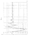
- FIG. 2 shows an exemplary profile of the load angle 5 of the rotor 7 of the generator 2 in degrees over the time t in seconds during a network fault, which results in a back-swing effect.
- vibrations of the load angle 5 occur during the network fault.
- the broken line shows the vibrations of the load angle 5 using conventional control measures relating to the network fault and the solid line shows the course of the load angle 5 when using the proposed method.
- the amplitude of the oscillation of the load angle 5 is reduced, resulting overall in a higher stability of the generator 2 during the network fault.
- a load angle 5 of + or - 180 degrees represents the slip limit and therefore, as can be seen, the generator 2 is already brought very close to the slip limit without the proposed method.
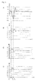
- FIG. 3 shows exemplary time profiles of load angle 5, rotational speed n, torque M L and amount m of a fuel introduced into an internal combustion engine 4 during a network fault in a power supply network 1.
- diagram A shows the course of the load angle 5 of a generator 2 connected to the internal combustion engine 4 (see Fig. 1 ) over time t.
- Diagram B shows the course of the rotational speed n of the internal combustion engine 4 over the time t.
- Diagram C shows the course of the mechanical torque M L on a motor shaft 8 of the internal combustion engine 4 over the time t.
- Diagram D shows the course of the amount m of a fuel introduced into the internal combustion engine 4 over the time t.
- a network fault occurs in the power supply network 1, to which the generator 2 is connected.
- the network fault shown here has the effect of a back-swing effect, as can be seen from the initially falling speed n of the internal combustion engine 4 which immediately follows the network fault. This results in a correspondingly increasing load angle 5 and an increasing mechanical torque M L on the motor shaft 8 of the internal combustion engine 4. Due to a detection of this speed change at time t 2 according to the proposed method, the amount m of introduced into the internal combustion engine 4 fuel elevated.
- the proposed method can increase the stability of electrical generators or power systems comprising at least one electric generator driven by an internal combustion engine in situations in which a back-swing effect triggered by a network fault occurs.
- conventional control measures are counterproductive because conventional control measures disregard the back-swing effect and, for example, throttle the amount of fuel to be injected into the engine rather than increasing it.
- the proposed method can be used in a network error only during the occurrence of a back-swing effect and after the decay of the back-swing effect conventional control measures can be taken again.
Landscapes
- Engineering & Computer Science (AREA)
- Mechanical Engineering (AREA)
- General Engineering & Computer Science (AREA)
- Chemical & Material Sciences (AREA)
- Combustion & Propulsion (AREA)
- Power Engineering (AREA)
- Physics & Mathematics (AREA)
- Fluid Mechanics (AREA)
- General Physics & Mathematics (AREA)
- Control Of Vehicle Engines Or Engines For Specific Uses (AREA)
- Control Of Eletrric Generators (AREA)
- Combined Controls Of Internal Combustion Engines (AREA)
Applications Claiming Priority (1)
| Application Number | Priority Date | Filing Date | Title |
|---|---|---|---|
| ATA832/2013A AT514811B1 (de) | 2013-10-30 | 2013-10-30 | Verfahren zum Betreiben einer mit einem elektrischen Generator, insbesondere Synchrongenerator, verbundenen Brennkraftmaschine |
Publications (3)
| Publication Number | Publication Date |
|---|---|
| EP2868903A2 true EP2868903A2 (fr) | 2015-05-06 |
| EP2868903A3 EP2868903A3 (fr) | 2015-12-23 |
| EP2868903B1 EP2868903B1 (fr) | 2016-12-28 |
Family
ID=51846482
Family Applications (1)
| Application Number | Title | Priority Date | Filing Date |
|---|---|---|---|
| EP14190675.0A Active EP2868903B1 (fr) | 2013-10-30 | 2014-10-28 | Procédé de fonctionnement d'un moteur à combustion interne relié à un générateur électrique |
Country Status (7)
| Country | Link |
|---|---|
| US (1) | US9926862B2 (fr) |
| EP (1) | EP2868903B1 (fr) |
| JP (1) | JP6071074B2 (fr) |
| KR (1) | KR101738122B1 (fr) |
| CN (1) | CN104595045B (fr) |
| AT (1) | AT514811B1 (fr) |
| ES (1) | ES2620795T3 (fr) |
Cited By (1)
| Publication number | Priority date | Publication date | Assignee | Title |
|---|---|---|---|---|
| EP3015688A1 (fr) * | 2014-10-30 | 2016-05-04 | GE Jenbacher GmbH & Co. OG | Procede destine au fonctionnement d'un moteur a combustion interne |
Families Citing this family (8)
| Publication number | Priority date | Publication date | Assignee | Title |
|---|---|---|---|---|
| AT514811B1 (de) | 2013-10-30 | 2015-04-15 | Ge Jenbacher Gmbh & Co Og | Verfahren zum Betreiben einer mit einem elektrischen Generator, insbesondere Synchrongenerator, verbundenen Brennkraftmaschine |
| AT517397B1 (de) * | 2015-07-07 | 2017-10-15 | Ge Jenbacher Gmbh & Co Og | Anordnung mit einem Synchrongenerator und einer Asynchronmaschine |
| AT518130A1 (de) * | 2015-12-29 | 2017-07-15 | Ge Jenbacher Gmbh & Co Og | Genset |
| EP3561988B1 (fr) * | 2018-04-24 | 2022-12-07 | Innio Jenbacher GmbH & Co OG | Synchronisation de réseau rapide |
| JP2020141432A (ja) * | 2019-02-26 | 2020-09-03 | 本田技研工業株式会社 | 発電機管理システム |
| KR102762289B1 (ko) * | 2024-05-20 | 2025-02-04 | 주식회사 대흥기전 | 축비틀림 검출을 이용하는 비상발전기시스템의 연료공급량제어장치 |
| KR102767752B1 (ko) * | 2024-06-05 | 2025-02-14 | 주식회사 대흥기전 | 순시전력 검출을 이용하는 비상발전기시스템의 연료공급량제어장치 |
| KR102767751B1 (ko) * | 2024-07-24 | 2025-02-14 | 주식회사 대흥기전 | 축비틀림의 전기적 검출을 이용하는 비상발전기시스템의 연료공급량제어장치 |
Family Cites Families (24)
| Publication number | Priority date | Publication date | Assignee | Title |
|---|---|---|---|---|
| US3529174A (en) * | 1966-08-08 | 1970-09-15 | Otto J M Smith | Power system with transient control and method |
| FR1576528A (fr) * | 1968-05-17 | 1969-08-01 | ||
| JP2875067B2 (ja) | 1991-07-26 | 1999-03-24 | 日野自動車工業株式会社 | 車両の補助駆動装置 |
| JP2934092B2 (ja) | 1992-03-17 | 1999-08-16 | 株式会社日立製作所 | 発電設備 |
| US6555929B1 (en) * | 2000-10-24 | 2003-04-29 | Kohler Co. | Method and apparatus for preventing excessive reaction to a load disturbance by a generator set |
| WO2004054065A1 (fr) * | 2002-12-06 | 2004-06-24 | Electric Power Research Institute, Inc. | Alimentation en electricite sans interruption et systeme de generation |
| JP2004257285A (ja) | 2003-02-25 | 2004-09-16 | Honda Motor Co Ltd | エンジン駆動式発電装置 |
| JP2005171890A (ja) | 2003-12-11 | 2005-06-30 | Osaka Gas Co Ltd | 発電設備 |
| JP2006211734A (ja) * | 2005-01-25 | 2006-08-10 | Denso Corp | トルク検出装置 |
| US7295914B2 (en) * | 2005-08-08 | 2007-11-13 | Deere & Company | Internal combustion engine with speed recovery power boost |
| DE102007045195B3 (de) | 2007-09-21 | 2009-03-12 | Mtu Friedrichshafen Gmbh | Verfahren zur Regelung eines stationären Gasmotors |
| US20090261599A1 (en) * | 2008-04-21 | 2009-10-22 | Glacier Bay, Inc. | Power generation system |
| PL2384540T3 (pl) | 2009-01-30 | 2015-05-29 | Siemens Ag | Inercja częstotliwości systemu mocy dla systemu generowania mocy |
| WO2010134994A1 (fr) * | 2009-05-20 | 2010-11-25 | Cummins Power Generation Ip, Inc. | Appareil, systèmes et procédés pour traiter des surtensions transitoires de charge électrique, des pannes électriques et des perturbations de réseau d'alimentation électrique |
| US8912672B2 (en) * | 2009-05-20 | 2014-12-16 | Cummins Power Generator IP, Inc. | Control of an engine-driven generator to address transients of an electrical power grid connected thereto |
| AT509436A1 (de) * | 2009-10-29 | 2011-08-15 | Ge Jenbacher Gmbh & Co Ohg | Stationäre kraftanlagen |
| AT509558B1 (de) | 2010-01-19 | 2012-09-15 | Ge Jenbacher Gmbh & Co Ohg | Stationäre kraftanlage |
| US8683980B2 (en) * | 2010-01-28 | 2014-04-01 | Cummins Power Generation, Inc. | Genset engine with an electronic fuel injection system integrating electrical sensing and crank position sensing |
| US9001053B2 (en) | 2010-10-28 | 2015-04-07 | Honeywell International Inc. | Display system for controlling a selector symbol within an image |
| DE102011105430A1 (de) * | 2011-06-20 | 2012-08-23 | Voith Patent Gmbh | Verfahren zum Betreiben eines Synchrongenerators |
| DE102012203334A1 (de) * | 2012-03-02 | 2013-09-05 | Wobben Properties Gmbh | Verfahren zum Betreiben eines Kombikraftwerks bzw. Kombikraftwerk |
| US10389126B2 (en) * | 2012-09-13 | 2019-08-20 | Stem, Inc. | Method and apparatus for damping power oscillations on an electrical grid using networked distributed energy storage systems |
| US20140366840A1 (en) * | 2013-06-17 | 2014-12-18 | Caterpillar Motoren GmbH & Co. KG. | Fuel Apportionment for Multi Fuel Engine System |
| AT514811B1 (de) | 2013-10-30 | 2015-04-15 | Ge Jenbacher Gmbh & Co Og | Verfahren zum Betreiben einer mit einem elektrischen Generator, insbesondere Synchrongenerator, verbundenen Brennkraftmaschine |
-
2013
- 2013-10-30 AT ATA832/2013A patent/AT514811B1/de active
-
2014
- 2014-10-28 ES ES14190675.0T patent/ES2620795T3/es active Active
- 2014-10-28 EP EP14190675.0A patent/EP2868903B1/fr active Active
- 2014-10-29 JP JP2014220089A patent/JP6071074B2/ja active Active
- 2014-10-29 US US14/527,210 patent/US9926862B2/en active Active
- 2014-10-29 CN CN201410783921.XA patent/CN104595045B/zh active Active
- 2014-10-30 KR KR1020140149530A patent/KR101738122B1/ko active Active
Non-Patent Citations (1)
| Title |
|---|
| None |
Cited By (2)
| Publication number | Priority date | Publication date | Assignee | Title |
|---|---|---|---|---|
| EP3015688A1 (fr) * | 2014-10-30 | 2016-05-04 | GE Jenbacher GmbH & Co. OG | Procede destine au fonctionnement d'un moteur a combustion interne |
| US10673363B2 (en) | 2014-10-30 | 2020-06-02 | GE Jenbacher GmbH CO OG | Regulating methods for operating an internal combustion engine upon network fault detection |
Also Published As
| Publication number | Publication date |
|---|---|
| US20150115616A1 (en) | 2015-04-30 |
| CN104595045B (zh) | 2018-03-30 |
| EP2868903B1 (fr) | 2016-12-28 |
| EP2868903A3 (fr) | 2015-12-23 |
| AT514811B1 (de) | 2015-04-15 |
| KR20150050494A (ko) | 2015-05-08 |
| US9926862B2 (en) | 2018-03-27 |
| KR101738122B1 (ko) | 2017-05-22 |
| ES2620795T3 (es) | 2017-06-29 |
| JP6071074B2 (ja) | 2017-02-01 |
| AT514811A4 (de) | 2015-04-15 |
| JP2015089334A (ja) | 2015-05-07 |
| CN104595045A (zh) | 2015-05-06 |
Similar Documents
| Publication | Publication Date | Title |
|---|---|---|
| EP2868903B1 (fr) | Procédé de fonctionnement d'un moteur à combustion interne relié à un générateur électrique | |
| DE112012006770B4 (de) | Zweiwellengasturbinen-Stromerzeugungssystem und Steuervorrichtung und Steuerverfahren für ein Gasturbinensystem | |
| EP3015688B1 (fr) | Procede destine au fonctionnement d'un moteur a combustion interne | |
| EP3284167B1 (fr) | Procédé pour la reconnaissance d'un glissement de pôle imminent | |
| EP2775267B1 (fr) | Procédé de détermination d'un angle de rotation de rotor | |
| EP2962388B1 (fr) | Procédé de reconnaissance de glissement de pôle | |
| EP3513491B1 (fr) | Procédé de mise en marche d'une machine synchrone à excitation permanente et machine synchrone à excitation permanente | |
| EP2869459B1 (fr) | Procédé de fonctionnement d'un générateur relié à un réseau d'alimentation électrique | |
| DE69936222T2 (de) | System und verfahren zum schutz eines elektromotors und dessen ansteuerschaltung, und ein elektromotor | |
| EP3048719B1 (fr) | Procede de fonctionnement d'un systeme comprenant une machine-outil rotative | |
| EP2860377B1 (fr) | Procédé de fonctionnement d'un moteur couplé à un générateur | |
| AT515033B1 (de) | Verfahren zum Betreiben einer mit einem Energieversorgungsnetz verbundenen Kraftanlage | |
| EP3411575B1 (fr) | Generateur électrique stationnaire | |
| EP3238338B1 (fr) | Procédé et dispositif de surveillance du fonctionnement d'une installation de production d'électricité | |
| DE3045687A1 (de) | Verfahren zur bereitstellung der maximal erforderlichen motorleistung fuer einen verbrennungsmotor, der zusammen mit einem generator ein bodenaggregat bildet | |
| DE10254345A1 (de) | Verfahren zur feldorientierten Regelung des Startvorgangs einer Elektromaschine | |
| EP3507476A1 (fr) | Détermination d'états de fonctionnement d'un moteur à combustion interne par un régulateur d'alternateur d'une machine électrique reliée au moteur à combustion interne | |
| DE102011088734A1 (de) | Generatorregler für einen Generator eines Kraftfahrzeugs mit einer Einrichtung zur Störgrößenaufschaltung | |
| DE2363565B2 (de) | Verfahren zum pruefen der gesamtleistung eines verbrennungsmotors und leistungspruefgeraet zum durchfuehren des verfahrens |
Legal Events
| Date | Code | Title | Description |
|---|---|---|---|
| PUAI | Public reference made under article 153(3) epc to a published international application that has entered the european phase |
Free format text: ORIGINAL CODE: 0009012 |
|
| 17P | Request for examination filed |
Effective date: 20141028 |
|
| AK | Designated contracting states |
Kind code of ref document: A2 Designated state(s): AL AT BE BG CH CY CZ DE DK EE ES FI FR GB GR HR HU IE IS IT LI LT LU LV MC MK MT NL NO PL PT RO RS SE SI SK SM TR |
|
| AX | Request for extension of the european patent |
Extension state: BA ME |
|
| PUAL | Search report despatched |
Free format text: ORIGINAL CODE: 0009013 |
|
| AK | Designated contracting states |
Kind code of ref document: A3 Designated state(s): AL AT BE BG CH CY CZ DE DK EE ES FI FR GB GR HR HU IE IS IT LI LT LU LV MC MK MT NL NO PL PT RO RS SE SI SK SM TR |
|
| AX | Request for extension of the european patent |
Extension state: BA ME |
|
| RIC1 | Information provided on ipc code assigned before grant |
Ipc: F02D 41/02 20060101AFI20151117BHEP Ipc: F02D 29/06 20060101ALI20151117BHEP Ipc: F02D 31/00 20060101ALI20151117BHEP Ipc: H02P 9/10 20060101ALI20151117BHEP |
|
| R17P | Request for examination filed (corrected) |
Effective date: 20160509 |
|
| RBV | Designated contracting states (corrected) |
Designated state(s): AL AT BE BG CH CY CZ DE DK EE ES FI FR GB GR HR HU IE IS IT LI LT LU LV MC MK MT NL NO PL PT RO RS SE SI SK SM TR |
|
| 17Q | First examination report despatched |
Effective date: 20160627 |
|
| GRAP | Despatch of communication of intention to grant a patent |
Free format text: ORIGINAL CODE: EPIDOSNIGR1 |
|
| INTG | Intention to grant announced |
Effective date: 20160919 |
|
| GRAS | Grant fee paid |
Free format text: ORIGINAL CODE: EPIDOSNIGR3 |
|
| STAA | Information on the status of an ep patent application or granted ep patent |
Free format text: STATUS: GRANT OF PATENT IS INTENDED |
|
| GRAA | (expected) grant |
Free format text: ORIGINAL CODE: 0009210 |
|
| STAA | Information on the status of an ep patent application or granted ep patent |
Free format text: STATUS: THE PATENT HAS BEEN GRANTED |
|
| AK | Designated contracting states |
Kind code of ref document: B1 Designated state(s): AL AT BE BG CH CY CZ DE DK EE ES FI FR GB GR HR HU IE IS IT LI LT LU LV MC MK MT NL NO PL PT RO RS SE SI SK SM TR |
|
| REG | Reference to a national code |
Ref country code: GB Ref legal event code: FG4D Free format text: NOT ENGLISH |
|
| REG | Reference to a national code |
Ref country code: CH Ref legal event code: EP |
|
| REG | Reference to a national code |
Ref country code: AT Ref legal event code: REF Ref document number: 857519 Country of ref document: AT Kind code of ref document: T Effective date: 20170115 |
|
| REG | Reference to a national code |
Ref country code: IE Ref legal event code: FG4D Free format text: LANGUAGE OF EP DOCUMENT: GERMAN |
|
| REG | Reference to a national code |
Ref country code: DE Ref legal event code: R096 Ref document number: 502014002318 Country of ref document: DE |
|
| PG25 | Lapsed in a contracting state [announced via postgrant information from national office to epo] |
Ref country code: LV Free format text: LAPSE BECAUSE OF FAILURE TO SUBMIT A TRANSLATION OF THE DESCRIPTION OR TO PAY THE FEE WITHIN THE PRESCRIBED TIME-LIMIT Effective date: 20161228 |
|
| REG | Reference to a national code |
Ref country code: NL Ref legal event code: FP |
|
| REG | Reference to a national code |
Ref country code: LT Ref legal event code: MG4D |
|
| PG25 | Lapsed in a contracting state [announced via postgrant information from national office to epo] |
Ref country code: SE Free format text: LAPSE BECAUSE OF FAILURE TO SUBMIT A TRANSLATION OF THE DESCRIPTION OR TO PAY THE FEE WITHIN THE PRESCRIBED TIME-LIMIT Effective date: 20161228 Ref country code: LT Free format text: LAPSE BECAUSE OF FAILURE TO SUBMIT A TRANSLATION OF THE DESCRIPTION OR TO PAY THE FEE WITHIN THE PRESCRIBED TIME-LIMIT Effective date: 20161228 Ref country code: NO Free format text: LAPSE BECAUSE OF FAILURE TO SUBMIT A TRANSLATION OF THE DESCRIPTION OR TO PAY THE FEE WITHIN THE PRESCRIBED TIME-LIMIT Effective date: 20170328 Ref country code: GR Free format text: LAPSE BECAUSE OF FAILURE TO SUBMIT A TRANSLATION OF THE DESCRIPTION OR TO PAY THE FEE WITHIN THE PRESCRIBED TIME-LIMIT Effective date: 20170329 |
|
| PG25 | Lapsed in a contracting state [announced via postgrant information from national office to epo] |
Ref country code: HR Free format text: LAPSE BECAUSE OF FAILURE TO SUBMIT A TRANSLATION OF THE DESCRIPTION OR TO PAY THE FEE WITHIN THE PRESCRIBED TIME-LIMIT Effective date: 20161228 Ref country code: RS Free format text: LAPSE BECAUSE OF FAILURE TO SUBMIT A TRANSLATION OF THE DESCRIPTION OR TO PAY THE FEE WITHIN THE PRESCRIBED TIME-LIMIT Effective date: 20161228 |
|
| REG | Reference to a national code |
Ref country code: ES Ref legal event code: FG2A Ref document number: 2620795 Country of ref document: ES Kind code of ref document: T3 Effective date: 20170629 |
|
| PG25 | Lapsed in a contracting state [announced via postgrant information from national office to epo] |
Ref country code: EE Free format text: LAPSE BECAUSE OF FAILURE TO SUBMIT A TRANSLATION OF THE DESCRIPTION OR TO PAY THE FEE WITHIN THE PRESCRIBED TIME-LIMIT Effective date: 20161228 Ref country code: SK Free format text: LAPSE BECAUSE OF FAILURE TO SUBMIT A TRANSLATION OF THE DESCRIPTION OR TO PAY THE FEE WITHIN THE PRESCRIBED TIME-LIMIT Effective date: 20161228 Ref country code: CZ Free format text: LAPSE BECAUSE OF FAILURE TO SUBMIT A TRANSLATION OF THE DESCRIPTION OR TO PAY THE FEE WITHIN THE PRESCRIBED TIME-LIMIT Effective date: 20161228 Ref country code: RO Free format text: LAPSE BECAUSE OF FAILURE TO SUBMIT A TRANSLATION OF THE DESCRIPTION OR TO PAY THE FEE WITHIN THE PRESCRIBED TIME-LIMIT Effective date: 20161228 Ref country code: IS Free format text: LAPSE BECAUSE OF FAILURE TO SUBMIT A TRANSLATION OF THE DESCRIPTION OR TO PAY THE FEE WITHIN THE PRESCRIBED TIME-LIMIT Effective date: 20170428 |
|
| PG25 | Lapsed in a contracting state [announced via postgrant information from national office to epo] |
Ref country code: BG Free format text: LAPSE BECAUSE OF FAILURE TO SUBMIT A TRANSLATION OF THE DESCRIPTION OR TO PAY THE FEE WITHIN THE PRESCRIBED TIME-LIMIT Effective date: 20170328 Ref country code: PL Free format text: LAPSE BECAUSE OF FAILURE TO SUBMIT A TRANSLATION OF THE DESCRIPTION OR TO PAY THE FEE WITHIN THE PRESCRIBED TIME-LIMIT Effective date: 20161228 Ref country code: SM Free format text: LAPSE BECAUSE OF FAILURE TO SUBMIT A TRANSLATION OF THE DESCRIPTION OR TO PAY THE FEE WITHIN THE PRESCRIBED TIME-LIMIT Effective date: 20161228 Ref country code: PT Free format text: LAPSE BECAUSE OF FAILURE TO SUBMIT A TRANSLATION OF THE DESCRIPTION OR TO PAY THE FEE WITHIN THE PRESCRIBED TIME-LIMIT Effective date: 20170428 |
|
| REG | Reference to a national code |
Ref country code: DE Ref legal event code: R097 Ref document number: 502014002318 Country of ref document: DE |
|
| REG | Reference to a national code |
Ref country code: FR Ref legal event code: PLFP Year of fee payment: 4 |
|
| PLBE | No opposition filed within time limit |
Free format text: ORIGINAL CODE: 0009261 |
|
| STAA | Information on the status of an ep patent application or granted ep patent |
Free format text: STATUS: NO OPPOSITION FILED WITHIN TIME LIMIT |
|
| PG25 | Lapsed in a contracting state [announced via postgrant information from national office to epo] |
Ref country code: DK Free format text: LAPSE BECAUSE OF FAILURE TO SUBMIT A TRANSLATION OF THE DESCRIPTION OR TO PAY THE FEE WITHIN THE PRESCRIBED TIME-LIMIT Effective date: 20161228 |
|
| 26N | No opposition filed |
Effective date: 20170929 |
|
| PG25 | Lapsed in a contracting state [announced via postgrant information from national office to epo] |
Ref country code: SI Free format text: LAPSE BECAUSE OF FAILURE TO SUBMIT A TRANSLATION OF THE DESCRIPTION OR TO PAY THE FEE WITHIN THE PRESCRIBED TIME-LIMIT Effective date: 20161228 |
|
| PG25 | Lapsed in a contracting state [announced via postgrant information from national office to epo] |
Ref country code: MC Free format text: LAPSE BECAUSE OF FAILURE TO SUBMIT A TRANSLATION OF THE DESCRIPTION OR TO PAY THE FEE WITHIN THE PRESCRIBED TIME-LIMIT Effective date: 20161228 |
|
| REG | Reference to a national code |
Ref country code: CH Ref legal event code: PL |
|
| REG | Reference to a national code |
Ref country code: IE Ref legal event code: MM4A |
|
| PG25 | Lapsed in a contracting state [announced via postgrant information from national office to epo] |
Ref country code: LU Free format text: LAPSE BECAUSE OF NON-PAYMENT OF DUE FEES Effective date: 20171028 Ref country code: LI Free format text: LAPSE BECAUSE OF NON-PAYMENT OF DUE FEES Effective date: 20171031 Ref country code: CH Free format text: LAPSE BECAUSE OF NON-PAYMENT OF DUE FEES Effective date: 20171031 |
|
| REG | Reference to a national code |
Ref country code: BE Ref legal event code: MM Effective date: 20171031 |
|
| PG25 | Lapsed in a contracting state [announced via postgrant information from national office to epo] |
Ref country code: BE Free format text: LAPSE BECAUSE OF NON-PAYMENT OF DUE FEES Effective date: 20171031 |
|
| REG | Reference to a national code |
Ref country code: FR Ref legal event code: PLFP Year of fee payment: 5 |
|
| PG25 | Lapsed in a contracting state [announced via postgrant information from national office to epo] |
Ref country code: MT Free format text: LAPSE BECAUSE OF FAILURE TO SUBMIT A TRANSLATION OF THE DESCRIPTION OR TO PAY THE FEE WITHIN THE PRESCRIBED TIME-LIMIT Effective date: 20161228 |
|
| PG25 | Lapsed in a contracting state [announced via postgrant information from national office to epo] |
Ref country code: IE Free format text: LAPSE BECAUSE OF NON-PAYMENT OF DUE FEES Effective date: 20171028 |
|
| PG25 | Lapsed in a contracting state [announced via postgrant information from national office to epo] |
Ref country code: HU Free format text: LAPSE BECAUSE OF FAILURE TO SUBMIT A TRANSLATION OF THE DESCRIPTION OR TO PAY THE FEE WITHIN THE PRESCRIBED TIME-LIMIT; INVALID AB INITIO Effective date: 20141028 |
|
| PG25 | Lapsed in a contracting state [announced via postgrant information from national office to epo] |
Ref country code: CY Free format text: LAPSE BECAUSE OF FAILURE TO SUBMIT A TRANSLATION OF THE DESCRIPTION OR TO PAY THE FEE WITHIN THE PRESCRIBED TIME-LIMIT Effective date: 20161228 |
|
| PG25 | Lapsed in a contracting state [announced via postgrant information from national office to epo] |
Ref country code: MK Free format text: LAPSE BECAUSE OF FAILURE TO SUBMIT A TRANSLATION OF THE DESCRIPTION OR TO PAY THE FEE WITHIN THE PRESCRIBED TIME-LIMIT Effective date: 20161228 |
|
| PG25 | Lapsed in a contracting state [announced via postgrant information from national office to epo] |
Ref country code: AL Free format text: LAPSE BECAUSE OF FAILURE TO SUBMIT A TRANSLATION OF THE DESCRIPTION OR TO PAY THE FEE WITHIN THE PRESCRIBED TIME-LIMIT Effective date: 20161228 |
|
| PGFP | Annual fee paid to national office [announced via postgrant information from national office to epo] |
Ref country code: TR Payment date: 20200928 Year of fee payment: 7 |
|
| REG | Reference to a national code |
Ref country code: AT Ref legal event code: MM01 Ref document number: 857519 Country of ref document: AT Kind code of ref document: T Effective date: 20191028 |
|
| PG25 | Lapsed in a contracting state [announced via postgrant information from national office to epo] |
Ref country code: AT Free format text: LAPSE BECAUSE OF NON-PAYMENT OF DUE FEES Effective date: 20191028 |
|
| P01 | Opt-out of the competence of the unified patent court (upc) registered |
Effective date: 20230614 |
|
| PGFP | Annual fee paid to national office [announced via postgrant information from national office to epo] |
Ref country code: FI Payment date: 20250923 Year of fee payment: 12 |
|
| PGFP | Annual fee paid to national office [announced via postgrant information from national office to epo] |
Ref country code: NL Payment date: 20250923 Year of fee payment: 12 Ref country code: IT Payment date: 20250923 Year of fee payment: 12 |
|
| PGFP | Annual fee paid to national office [announced via postgrant information from national office to epo] |
Ref country code: GB Payment date: 20250923 Year of fee payment: 12 |
|
| PGFP | Annual fee paid to national office [announced via postgrant information from national office to epo] |
Ref country code: FR Payment date: 20250923 Year of fee payment: 12 |
|
| PGFP | Annual fee paid to national office [announced via postgrant information from national office to epo] |
Ref country code: DE Payment date: 20250923 Year of fee payment: 12 |
|
| PGFP | Annual fee paid to national office [announced via postgrant information from national office to epo] |
Ref country code: ES Payment date: 20251103 Year of fee payment: 12 |