EP2868930B1 - Hydraulikschaltung für eine baumaschine und steuerungsvorrichtung dafür - Google Patents
Hydraulikschaltung für eine baumaschine und steuerungsvorrichtung dafür Download PDFInfo
- Publication number
- EP2868930B1 EP2868930B1 EP13813005.9A EP13813005A EP2868930B1 EP 2868930 B1 EP2868930 B1 EP 2868930B1 EP 13813005 A EP13813005 A EP 13813005A EP 2868930 B1 EP2868930 B1 EP 2868930B1
- Authority
- EP
- European Patent Office
- Prior art keywords
- directional control
- control valve
- construction machine
- center bypass
- pressurized oil
- Prior art date
- Legal status (The legal status is an assumption and is not a legal conclusion. Google has not performed a legal analysis and makes no representation as to the accuracy of the status listed.)
- Active
Links
Images




Classifications
-
- E—FIXED CONSTRUCTIONS
- E02—HYDRAULIC ENGINEERING; FOUNDATIONS; SOIL SHIFTING
- E02F—DREDGING; SOIL-SHIFTING
- E02F9/00—Component parts of dredgers or soil-shifting machines, not restricted to one of the kinds covered by groups E02F3/00 - E02F7/00
- E02F9/20—Drives; Control devices
- E02F9/22—Hydraulic or pneumatic drives
- E02F9/2278—Hydraulic circuits
- E02F9/2282—Systems using center bypass type changeover valves
-
- E—FIXED CONSTRUCTIONS
- E02—HYDRAULIC ENGINEERING; FOUNDATIONS; SOIL SHIFTING
- E02F—DREDGING; SOIL-SHIFTING
- E02F9/00—Component parts of dredgers or soil-shifting machines, not restricted to one of the kinds covered by groups E02F3/00 - E02F7/00
- E02F9/20—Drives; Control devices
- E02F9/22—Hydraulic or pneumatic drives
- E02F9/2221—Control of flow rate; Load sensing arrangements
- E02F9/2239—Control of flow rate; Load sensing arrangements using two or more pumps with cross-assistance
- E02F9/2242—Control of flow rate; Load sensing arrangements using two or more pumps with cross-assistance including an electronic controller
-
- E—FIXED CONSTRUCTIONS
- E02—HYDRAULIC ENGINEERING; FOUNDATIONS; SOIL SHIFTING
- E02F—DREDGING; SOIL-SHIFTING
- E02F9/00—Component parts of dredgers or soil-shifting machines, not restricted to one of the kinds covered by groups E02F3/00 - E02F7/00
- E02F9/20—Drives; Control devices
- E02F9/22—Hydraulic or pneumatic drives
- E02F9/2264—Arrangements or adaptations of elements for hydraulic drives
- E02F9/2267—Valves or distributors
-
- E—FIXED CONSTRUCTIONS
- E02—HYDRAULIC ENGINEERING; FOUNDATIONS; SOIL SHIFTING
- E02F—DREDGING; SOIL-SHIFTING
- E02F9/00—Component parts of dredgers or soil-shifting machines, not restricted to one of the kinds covered by groups E02F3/00 - E02F7/00
- E02F9/20—Drives; Control devices
- E02F9/22—Hydraulic or pneumatic drives
- E02F9/2278—Hydraulic circuits
- E02F9/2292—Systems with two or more pumps
-
- F—MECHANICAL ENGINEERING; LIGHTING; HEATING; WEAPONS; BLASTING
- F15—FLUID-PRESSURE ACTUATORS; HYDRAULICS OR PNEUMATICS IN GENERAL
- F15B—SYSTEMS ACTING BY MEANS OF FLUIDS IN GENERAL; FLUID-PRESSURE ACTUATORS, e.g. SERVOMOTORS; DETAILS OF FLUID-PRESSURE SYSTEMS, NOT OTHERWISE PROVIDED FOR
- F15B11/00—Servomotor systems without provision for follow-up action; Circuits therefor
- F15B11/16—Servomotor systems without provision for follow-up action; Circuits therefor with two or more servomotors
-
- F—MECHANICAL ENGINEERING; LIGHTING; HEATING; WEAPONS; BLASTING
- F15—FLUID-PRESSURE ACTUATORS; HYDRAULICS OR PNEUMATICS IN GENERAL
- F15B—SYSTEMS ACTING BY MEANS OF FLUIDS IN GENERAL; FLUID-PRESSURE ACTUATORS, e.g. SERVOMOTORS; DETAILS OF FLUID-PRESSURE SYSTEMS, NOT OTHERWISE PROVIDED FOR
- F15B11/00—Servomotor systems without provision for follow-up action; Circuits therefor
- F15B11/16—Servomotor systems without provision for follow-up action; Circuits therefor with two or more servomotors
- F15B11/17—Servomotor systems without provision for follow-up action; Circuits therefor with two or more servomotors using two or more pumps
-
- F—MECHANICAL ENGINEERING; LIGHTING; HEATING; WEAPONS; BLASTING
- F15—FLUID-PRESSURE ACTUATORS; HYDRAULICS OR PNEUMATICS IN GENERAL
- F15B—SYSTEMS ACTING BY MEANS OF FLUIDS IN GENERAL; FLUID-PRESSURE ACTUATORS, e.g. SERVOMOTORS; DETAILS OF FLUID-PRESSURE SYSTEMS, NOT OTHERWISE PROVIDED FOR
- F15B2211/00—Circuits for servomotor systems
- F15B2211/20—Fluid pressure source, e.g. accumulator or variable axial piston pump
- F15B2211/205—Systems with pumps
- F15B2211/2053—Type of pump
- F15B2211/20546—Type of pump variable capacity
-
- F—MECHANICAL ENGINEERING; LIGHTING; HEATING; WEAPONS; BLASTING
- F15—FLUID-PRESSURE ACTUATORS; HYDRAULICS OR PNEUMATICS IN GENERAL
- F15B—SYSTEMS ACTING BY MEANS OF FLUIDS IN GENERAL; FLUID-PRESSURE ACTUATORS, e.g. SERVOMOTORS; DETAILS OF FLUID-PRESSURE SYSTEMS, NOT OTHERWISE PROVIDED FOR
- F15B2211/00—Circuits for servomotor systems
- F15B2211/20—Fluid pressure source, e.g. accumulator or variable axial piston pump
- F15B2211/205—Systems with pumps
- F15B2211/20576—Systems with pumps with multiple pumps
-
- F—MECHANICAL ENGINEERING; LIGHTING; HEATING; WEAPONS; BLASTING
- F15—FLUID-PRESSURE ACTUATORS; HYDRAULICS OR PNEUMATICS IN GENERAL
- F15B—SYSTEMS ACTING BY MEANS OF FLUIDS IN GENERAL; FLUID-PRESSURE ACTUATORS, e.g. SERVOMOTORS; DETAILS OF FLUID-PRESSURE SYSTEMS, NOT OTHERWISE PROVIDED FOR
- F15B2211/00—Circuits for servomotor systems
- F15B2211/30—Directional control
- F15B2211/305—Directional control characterised by the type of valves
- F15B2211/3056—Assemblies of multiple valves
- F15B2211/3059—Assemblies of multiple valves having multiple valves for multiple output members
- F15B2211/30595—Assemblies of multiple valves having multiple valves for multiple output members with additional valves between the groups of valves for multiple output members
-
- F—MECHANICAL ENGINEERING; LIGHTING; HEATING; WEAPONS; BLASTING
- F15—FLUID-PRESSURE ACTUATORS; HYDRAULICS OR PNEUMATICS IN GENERAL
- F15B—SYSTEMS ACTING BY MEANS OF FLUIDS IN GENERAL; FLUID-PRESSURE ACTUATORS, e.g. SERVOMOTORS; DETAILS OF FLUID-PRESSURE SYSTEMS, NOT OTHERWISE PROVIDED FOR
- F15B2211/00—Circuits for servomotor systems
- F15B2211/30—Directional control
- F15B2211/315—Directional control characterised by the connections of the valve or valves in the circuit
- F15B2211/31505—Directional control characterised by the connections of the valve or valves in the circuit being connected to a pressure source and a return line
- F15B2211/31517—Directional control characterised by the connections of the valve or valves in the circuit being connected to a pressure source and a return line having multiple pressure sources
-
- F—MECHANICAL ENGINEERING; LIGHTING; HEATING; WEAPONS; BLASTING
- F15—FLUID-PRESSURE ACTUATORS; HYDRAULICS OR PNEUMATICS IN GENERAL
- F15B—SYSTEMS ACTING BY MEANS OF FLUIDS IN GENERAL; FLUID-PRESSURE ACTUATORS, e.g. SERVOMOTORS; DETAILS OF FLUID-PRESSURE SYSTEMS, NOT OTHERWISE PROVIDED FOR
- F15B2211/00—Circuits for servomotor systems
- F15B2211/30—Directional control
- F15B2211/32—Directional control characterised by the type of actuation
- F15B2211/327—Directional control characterised by the type of actuation electrically or electronically
-
- F—MECHANICAL ENGINEERING; LIGHTING; HEATING; WEAPONS; BLASTING
- F15—FLUID-PRESSURE ACTUATORS; HYDRAULICS OR PNEUMATICS IN GENERAL
- F15B—SYSTEMS ACTING BY MEANS OF FLUIDS IN GENERAL; FLUID-PRESSURE ACTUATORS, e.g. SERVOMOTORS; DETAILS OF FLUID-PRESSURE SYSTEMS, NOT OTHERWISE PROVIDED FOR
- F15B2211/00—Circuits for servomotor systems
- F15B2211/40—Flow control
- F15B2211/415—Flow control characterised by the connections of the flow control means in the circuit
- F15B2211/41554—Flow control characterised by the connections of the flow control means in the circuit being connected to a return line and a directional control valve
-
- F—MECHANICAL ENGINEERING; LIGHTING; HEATING; WEAPONS; BLASTING
- F15—FLUID-PRESSURE ACTUATORS; HYDRAULICS OR PNEUMATICS IN GENERAL
- F15B—SYSTEMS ACTING BY MEANS OF FLUIDS IN GENERAL; FLUID-PRESSURE ACTUATORS, e.g. SERVOMOTORS; DETAILS OF FLUID-PRESSURE SYSTEMS, NOT OTHERWISE PROVIDED FOR
- F15B2211/00—Circuits for servomotor systems
- F15B2211/40—Flow control
- F15B2211/45—Control of bleed-off flow, e.g. control of bypass flow to the return line
-
- F—MECHANICAL ENGINEERING; LIGHTING; HEATING; WEAPONS; BLASTING
- F15—FLUID-PRESSURE ACTUATORS; HYDRAULICS OR PNEUMATICS IN GENERAL
- F15B—SYSTEMS ACTING BY MEANS OF FLUIDS IN GENERAL; FLUID-PRESSURE ACTUATORS, e.g. SERVOMOTORS; DETAILS OF FLUID-PRESSURE SYSTEMS, NOT OTHERWISE PROVIDED FOR
- F15B2211/00—Circuits for servomotor systems
- F15B2211/60—Circuit components or control therefor
- F15B2211/63—Electronic controllers
- F15B2211/6303—Electronic controllers using input signals
- F15B2211/6346—Electronic controllers using input signals representing a state of input means, e.g. joystick position
-
- F—MECHANICAL ENGINEERING; LIGHTING; HEATING; WEAPONS; BLASTING
- F15—FLUID-PRESSURE ACTUATORS; HYDRAULICS OR PNEUMATICS IN GENERAL
- F15B—SYSTEMS ACTING BY MEANS OF FLUIDS IN GENERAL; FLUID-PRESSURE ACTUATORS, e.g. SERVOMOTORS; DETAILS OF FLUID-PRESSURE SYSTEMS, NOT OTHERWISE PROVIDED FOR
- F15B2211/00—Circuits for servomotor systems
- F15B2211/60—Circuit components or control therefor
- F15B2211/665—Methods of control using electronic components
- F15B2211/6652—Control of the pressure source, e.g. control of the swash plate angle
-
- F—MECHANICAL ENGINEERING; LIGHTING; HEATING; WEAPONS; BLASTING
- F15—FLUID-PRESSURE ACTUATORS; HYDRAULICS OR PNEUMATICS IN GENERAL
- F15B—SYSTEMS ACTING BY MEANS OF FLUIDS IN GENERAL; FLUID-PRESSURE ACTUATORS, e.g. SERVOMOTORS; DETAILS OF FLUID-PRESSURE SYSTEMS, NOT OTHERWISE PROVIDED FOR
- F15B2211/00—Circuits for servomotor systems
- F15B2211/60—Circuit components or control therefor
- F15B2211/665—Methods of control using electronic components
- F15B2211/6654—Flow rate control
-
- F—MECHANICAL ENGINEERING; LIGHTING; HEATING; WEAPONS; BLASTING
- F15—FLUID-PRESSURE ACTUATORS; HYDRAULICS OR PNEUMATICS IN GENERAL
- F15B—SYSTEMS ACTING BY MEANS OF FLUIDS IN GENERAL; FLUID-PRESSURE ACTUATORS, e.g. SERVOMOTORS; DETAILS OF FLUID-PRESSURE SYSTEMS, NOT OTHERWISE PROVIDED FOR
- F15B2211/00—Circuits for servomotor systems
- F15B2211/70—Output members, e.g. hydraulic motors or cylinders or control therefor
- F15B2211/71—Multiple output members, e.g. multiple hydraulic motors or cylinders
- F15B2211/7142—Multiple output members, e.g. multiple hydraulic motors or cylinders the output members being arranged in multiple groups
Definitions
- the present invention relates to a hydraulic circuit for a construction machine and a control device for the same.
- Some construction machines perform a control (a bleed-off control) of returning a part (e.g., an excess) of a pressurized oil discharged from a hydraulic pump to an operating oil tank.
- a control a bleed-off control
- some construction machines have a gap (e.g., a bleed opening Sbo) for returning the pressurized oil in a spool of a directional control valve.
- the construction machine performs the bleed-off control by changing the opening area of the bleed opening.
- EP 2 157 245 A2 discloses a hydraulic system for construction equipment, which can increase the driving speed of a corresponding working device by making hydraulic fluid of a hydraulic pump, which is added to the hydraulic system having two hydraulic pumps in the construction equipment, join hydraulic fluid on the working device side, and can intercept the supply of hydraulic fluid from the working device side to a traveling apparatus side when the working device and the traveling apparatus are simultaneously manipulated.
- the hydraulic system for construction equipment includes first and second variable displacement hydraulic pumps connected to an engine; a first traveling control valve installed in a center bypass path of a first hydraulic pump; first control valves for controlling hydraulic fluid supplied to a swing motor and an arm cylinder; a second traveling control valve for controlling the start, stop, and direction change of a right traveling motor; second control valves for controlling hydraulic fluid supplied to a boom cylinder and a bucket cylinder; and a third variable displacement hydraulic pump connected to the center bypass path of the second hydraulic pump through a branch flow path. If a corresponding actuator is driven, hydraulic fluid from the third hydraulic pump joins hydraulic fluid of the actuator to increase the driving speed of the actuator.
- EP 0 816 576 A1 discloses a construction machine of a small rotational inertia such as an intra-width swing machine or a small-sized excavator, wherein a rotative operability varies depending on the posture of a working attachment, and in a reduced state of reach, a change in rotating force is oversensitive to the operation of a working lever, so operation is difficult.
- means for detecting the operation of a rotating direction control valve is provided and an outlet of a center bypassing oil path in the rotating direction control valve and an oil tank are brought into communication with each other through a cut-off valve used for controlling the bleed-off thereof.
- a pilot port of the cut-off valve and a source of a pilot oil pressure are brought into communication with each other through an electromagnetic proportional pressure reducing valve, and an operation command signal is issued from a controller to the electromagnetic proportional pressure control valve to control the acceleration of rotation and the maximum rotating speed.
- EP 1 577 563 A2 discloses a hydraulic control device for a working machine which includes hydraulic actuators, a hydraulic pump which functions as a hydraulic power source, control valves which control the actuators on the basis of operations by an operating unit, a common bleed-off valve which returns excess oil to a tank via an unload passage on the basis of the operations by the operating unit, and a control unit which controls the common bleed-off valve.
- the common bleed-off valve is capable of setting a position for closing the unload passage when the common bleed-off valve is in a non-operating state.
- the control valves have center bypass passages which function as individual bleed-off passages which open when the control valves are in neutral states. Opening characteristics of the control valves are set such that the center bypass passages are closed in initial stroke periods in which the control valves move toward operating positions.
- the amount of the pressurized oil (an operating oil) supplied to a hydraulic actuator differs depending on an object of a work. Therefore, in some construction machines having multiple hydraulic pumps, pressurized oils discharged from the hydraulic pump are merged to keep the amount of the pressurized oil supplied to the hydraulic actuator.
- the merging circuit is added to the technique disclosed in JP H11-257302 A , it is necessary to provide another set of a cut valve Vct, an output port Pout, and so on in order to merge the pressurized oils bi-directionally. Said differently, in a case where the merging circuit is added to the technique disclosed in JP H11-257302 A , the size of the hydraulic circuit of the construction machine may become great by existences of the cut valve Vct, the output port Pout, and so on.
- the present invention is provided under this situation, and the object is to provide a hydraulic circuit of a construction machine that includes multiple center bypass passages to which pressurized oil discharged from multiple hydraulic pumps are respectively supplied and a merging circuit for merging the pressurized oil supplied to a center bypass passage thereby enabling a control of the pressurized oil to be merged, and a control device for the construction machine.
- the hydraulic circuit of the construction machine wherein the first internal passage has substantially a same passage area regardless of a position of a spool included in each directional control valve and forms the parallel passage corresponding to the passage area, wherein the directional control valve group is supplied with the pressurized oil from only the parallel passage.
- a hydraulic circuit of a construction machine including a plurality of center bypass passages, into which a pressurized oil discharged from a plurality of hydraulic pumps is supplied, including a directional control valve group including a plurality of directional control valves that are arranged in tandem with the center bypass passages; a bleed-off valve arranged on a downstream side of each center bypass passage relative to the directional control valve group; and a merging circuit that merges the pressurized oil supplied into one center bypass passage of the plurality of center bypass passages and the pressurized oil in another center bypass passage of the plurality of center bypass passages, wherein each directional control valve includes a first internal passage that flows the pressurized oil supplied into the directional control valve out into the center bypass passages, and a second internal passage that supplies the pressurized oil supplied to the directional control valve to a hydraulic actuator of the construction machine, wherein the center bypass passages and the first internal passage form a parallel passage where the first internal passage flows the pressurized oil discharged from the hydraulic pump
- the hydraulic circuit of the construction machine wherein the merging circuit further includes a check valve corresponding to the inflow direction, and prevents the pressurized oil from flowing in a direction inverse to the inflow direction.
- a construction machine including a control device for controlling a hydraulic circuit of a construction machine, as set forth in claim 5.
- Preferred embodiments of the present invention may be gathered from the dependent claims.
- a merging circuit and a merging directional control valve are used to control the inflow direction of the pressurized oil to be merged.
- a construction machine 100 including a hydraulic circuit 20 of the embodiment of the present invention and a device 30 of controlling the hydraulic circuit are used in describing the present invention.
- the present invention is applicable to other than the embodiment as long as a construction machine includes multiple center bypass passages (center bypass lines), flows back (performs a bleed-off control) a part of a pressurized oil using a cut valve (a bleed-off valve, a flow control valve, etc.), and supplies (merges) the pressurized oil supplied to one center bypass passage of the multiple center bypass passages.
- the construction machine to which the present invention is applicable is a hydraulic shovel, a crane vehicle, a bulldozer, a wheel loader, a dump truck, a pile hammer, a pile extractor, a water jet, mud discharging water processing facilities, a grout mixer, a construction machine for deep fundamental, a boring machine, or the like.
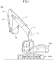
- FIG. 1 a schematic structure of a construction machine 100, to which the present invention is applicable, is described.
- the construction machine of the embodiment is a machine performing a desired work using a hydraulic actuator.
- the construction machine 100 includes hydraulic actuators such as a boom 11 whose base end portion is supported by an upper-part swiveling body 10Up so as to be rotatable, an arm 12 which is supported by a tip end of the boom 11 so as to be rotatable, and a bucket 13 supported by a tip end of the arm 12 so as to be rotatable.
- hydraulic actuators such as a boom 11 whose base end portion is supported by an upper-part swiveling body 10Up so as to be rotatable, an arm 12 which is supported by a tip end of the boom 11 so as to be rotatable, and a bucket 13 supported by a tip end of the arm 12 so as to be rotatable.
- the boom cylinder 11c is expanded and contracted in a longitudinal direction of the boom cylinder 11c by supplying the operating oil (the pressurized oil) to the boom cylinder 11c of the boom 11. At this time, the boom 11 is driven in upward and downward directions by the expansion and contraction of the boom cylinder 11c.
- the construction machine 100 controls the operating oil supplied to the boom cylinder 11c using a directional control valve (e.g., Vb1 and Vb2 illustrated in FIG. 2 described later) for the boom which is controlled in response to the operation amount and the operation direction of an operation lever operated by an operator (a driver, a worker). As a result, the construction machine 100 performs a desired work in response to the operation amount or the like of the operation lever operated by the operator.
- a directional control valve e.g., Vb1 and Vb2 illustrated in FIG. 2 described later
- the arm 12 and the bucket 13 are driven by expansion and contraction of the arm cylinder 12c and a bucket cylinder 13c.
- the operating oil supplied to the arm cylinder 12c and the bucket cylinder 13c is controlled by a directional control valve for the arm (e.g., Va1 and Va2 illustrated in FIG. 2 ) and a directional control valve for the bucket (e.g., Vbk illustrated in FIG. 2 ).
- a main body of the construction machine 100 travels (movements in the forward, backward, rightward, and leftward directions) and rotates (a swivel motion) using wheels and a swiveling apparatus (e.g., the lower-part traveling body 10Dw).
- the construction machine 100 uses a directional control valve for travel (e.g., Vt1, Vt2, and Vst illustrated in FIG. 2 ) or the like to cause the construction machine 100 to travel in response to the operation amount of the operation lever operated by the operator.
- the construction machine 100 further includes the hydraulic circuit 20 (described later) for supplying the operating oil (the pressurized oil) from the hydraulic pump to the hydraulic actuator and a device 30 (described later) for controlling operations of elements of the construction machine 100.
- solid lines indicate oil passages (passages of the pressurized oil). However, solid lines marked with "//" indicate an electric control system.
- the hydraulic circuit, to which the present invention is applicable is not limited to that illustrated in FIG. 2 .
- the present invention is applicable to any hydraulic circuit as long as the hydraulic circuit includes multiple center bypass passages and is provided with a cut valve (a bleed-off valve) in a center bypass passage on the downstream side of the multiple directional control valves (a directional control valve group).
- the hydraulic circuit 20 has two hydraulic pumps, the hydraulic circuit, to which the present invention is applicable, is not limited to that having two hydraulic pumps. Said differently, the present invention is applicable to the hydraulic circuit (the construction machine) having three or more hydraulic pumps.
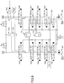
- the hydraulic circuit 20 of the construction machine 100 of the embodiment of the present invention includes two hydraulic pumps P (first and second hydraulic pumps) mechanically connected to an output shaft of a power source (not illustrated) such as a generating machinery, an engine, a motor, or the like, two center bypass passages RC (a first center bypass passage RC1 and a second center bypass passage RC2), to which the pressurized oil is discharged from the two hydraulic pumps P, respectively, a directional control valve (a first directional control valve Vt1 for travel or the like) for controlling the hydraulic actuator (e.g., the boom 11 or the like), and a directional control valve (a straight travel valve) Vst for straight travel.
- a power source such as a generating machinery, an engine, a motor, or the like
- two center bypass passages RC a first center bypass passage RC1 and a second center bypass passage RC2
- a directional control valve a first directional control valve Vt1 for travel or the like
- Vt1 for travel or the like
- the hydraulic circuit 20 includes a bleed-off valve Vbo (a first bleed-off valve Vbo1 and a second bleed-off valve Vbo2) arranged on the downstream side (for example, the most downstream side) of the center bypass passage RC. Furthermore, the hydraulic circuit 20 has a merging circuit RJ which supplies the pressurized oil supplied into the multiple center bypass passages to another center bypass passage (hereinafter, referred to as "merging").
- Vbo a first bleed-off valve Vbo1 and a second bleed-off valve Vbo2
- the directional control valves (Vt1 or the like) is arranged in the center bypass passage RC in series, and the bleed-off valve Vbo is arranged in a downstream side of the center bypass passage RC.
- the first center bypass passage RC1 corresponding to the first hydraulic pump P1 includes the first directional control valve Vt1 for travel (e.g., a directional control valve for left travel), an auxiliary directional control valve Vop, a directional control valve Vsw for swivel, the directional control valve Vb2 for a second boom, the directional control valve Va1 for a first arm, and the first bleed-off valve Vbo1, which are arranged in series.
- the second center bypass passage RC2 corresponding to the second hydraulic pump P2 includes the second directional control valve Vt2 for travel (e.g., a directional control valve for right travel), a directional control valve Vbk for a bucket, the directional control valve Vb1 for a first boom, the directional control valve Va2 for a second arm, and the second bleed-off valve Vbo2, which are arranged in series. Further, the hydraulic circuit 20 is provided with the straight travel valve Vst on the upstream side of the second center bypass passage RC2.
- multiple directional control valves are arranged in series in the center bypass passage RC.
- the directional control valves are arranged in tandem by arranging multiple directional control valves in the two center bypass passages RC1 and RC2, respectively, in series so that the directional control valves are arranged in tandem.
- a group of the multiple directional control valves arranged in tandem in the center bypass passage RC is referred to as a "directional control valve group”.
- a remote control pressure (a secondary pressure of a remote control valve) generated in response to operation information (e.g., information related to the operation amount, information related to the operation direction, hereinafter, referred to as "operation information") is input in the directional control valve (e.g., Vt1) corresponding to an operation of an operation lever operated by an operator.
- the directional control valve switches the position of the spool in response to the remote control pressure introduced into the both ends of the spool (a flow rate control spool), and controls the flow rate (the operation amount) and the direction (the operation direction) of the pressurized oil (the operating oil).
- a part (an excess) of the pressurized oil discharged from the hydraulic pump P (e.g., P1) is flown back to an operating oil tank Tnk (the bleed-off control) using the bleed-off valve Vbo (e.g., Vbo1) that is arranged on the downstream side of the center bypass passage RC (e.g., RC1).
- Vbo e.g., Vbo1
- the flow rate of the operating oil (the pressurized oil) supplied to the hydraulic cylinder (e.g., 11c) is controlled and the drive (the operation) of the hydraulic actuator (e.g., 11 illustrated in FIG. 1 ) is controlled.
- the bleed-off valve Vbo of the embodiment can be set at an unloading position where the opening area of the bleed-off valve Vbo is maximum and a blocking position where the opening area of the bleed-off valve Vbo is zero.
- the bleed-off valve Vbo is switched from the unloading position to the blocking position using (the pressure of) the pressurized oil of a pilot pump Pp controlled by the control device for the construction machine.
- the opening area of the bleed-off valve Vbo is changed.
- the bleed-off valve Vbo can flow back (return) the pressurized oil by a desirable flow rate corresponding to the changed opening area to the operating oil tank.
- the pressurized oil supplied to one center bypass passage is merged to another center bypass passage using the merging circuit RJ.
- the merging circuit RJ includes a merging directional control valve RJ that controls a flowing direction (hereinafter, referred to as an "inflow direction") of the pressurized oil supplied into the merging circuit RJ as illustrated in FIG. 2 .
- the merging circuit RJ inputs the pressurized oil provided by the pilot pump Pp (a first pilot pump Pp1 and a second pilot pump Pp2) to a pilot port (a control port) of the merging directional control valve Vj. With this, the hydraulic circuit 20 (the merging circuit RJ) controls the merging directional control valve Vj.
- the merging circuit RJ of the embodiment uses the merging directional control valve Vj based on operation information input by the operator using the operation lever so that it is selected (controlled) to merge the pressurized oil supplied to the center bypass passage RC1 and the pressurized oil supplied to the center bypass passage or to merge the pressurized oil supplied to the center bypass passage RC2 and the pressurized oil supplied to the center bypass passage RC1.
- the hydraulic circuit 20 (the merging circuit RJ) of the construction machine 100 of the embodiment can merge the pressurized oils in both directions toward the center bypass passages RC1 and RC2.
- the operation of merging the pressurized oils using the merging circuit RJ or the like in the hydraulic circuit 20 is described later in (Operation of merging pressurized oil).
- the hydraulic circuit 20 (the merging circuit RJ) of the construction machine 100, to which the present invention is applicable, may be structured so that the pressurized oil merges into only one of the center bypass passages RC1 and RC2.
- An internal passage RV of the directional control valve arranged in the hydraulic circuit 20 of the construction machine 100 of the embodiment is described as follows.
- the hydraulic circuit 20 of the embodiment includes the directional control valve group (the multiple directional control valves). Further, each of the directional control valves of the embodiment includes, as the internal passage RV, a first internal passage for flowing the pressurized oil, which is supplied, into the center bypass passage RC and a second internal passage for flowing the pressurized oil, which is supplied, into the hydraulic actuator. Said differently, each of the multiple directional control valves forming the directional control valve group includes the first internal passage and the second internal passage.
- the opening of the first internal passage is not completely closed in a case where the position of the spool of the directional control valve is switched over.
- the passage area of the first internal passage of the embodiment is substantially the same regardless of the position of the spool of the directional control valve.
- the substantially same passage area means that an effective passage area, through which the pressurized oil actually passes, does not substantially change in comparison with the passage area changing by the position change of the spool.
- a parallel passage can be formed by the center bypass passage RC and the first internal passage.
- the parallel passage corresponding to the passage area of the first internal passage can be formed.
- the pressurized oil can be supplied from only the formed parallel passage to the directional control valve group (the multiple directional control valves).
- the directional control valve for travel (e.g., Vt1, Vt2 illustrated in FIG. 2 ) may be structured so that the opening of the first internal passage is completely closed (for example, RV1t illustrated in FIG. 2 ).
- the hydraulic circuit 20 of) the construction machine 100 can maintain stability of travel (the flow rate of the operating oil necessary for the travel) during the travel.
- the bleed-off control (a standardized bleed-off control) can be performed using the bleed-off valve Vbo arranged on the most downstream side of the center bypass passage RC as described above.
- the second internal passage of the embodiment is the internal passage (e.g., RV2 illustrated in FIG. 2 ) for supplying the pressurized oil to the hydraulic cylinder (e.g., the arm cylinder 12c illustrated in FIG. 2 ).
- the second internal passage supplies the pressurized oil discharged from the hydraulic pump P to the hydraulic cylinder (e.g., the arm cylinder 12c illustrated in FIG. 2 ).
- the second internal passage of the embodiment changes the route of the internal passage and changes the flow rate of the pressurized oil (the operating oil) supplied to the hydraulic cylinder and the direction (the operation direction) of the pressurized oil supplied to the hydraulic cylinder in a case where the position of the spool of the directional control valve is switched by the input remote control pressure.
- the directional control valve (the construction machine 100) can control the operation of the hydraulic cylinder (the hydraulic actuator).
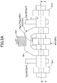
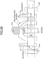
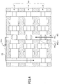
- FIGs. 3A-3C An example of the internal passage RV (a shape of the spool) of the directional control valve arranged in the hydraulic circuit 20 of the construction machine 100 is specifically described with reference to FIGs. 3A-3C .
- the directional control valve e.g., the shape of the spool which can be used in the present invention is not limited to those illustrated in FIGs. 3A-3C .
- the directional control valve V of the hydraulic circuit 20 of the embodiment includes an inlet port PIprt to which the pressurized oil is supplied through the center bypass passage RC, an outlet port POprt from which the pressurized oil supplied from the inlet port is flown into the center bypass passage RC, a cylinder port Cprt which supplies the pressurized oil supplied to the directional control valve V to the hydraulic cylinder, and a tank port Tprt which ejects the pressurized oil ejected from the hydraulic cylinder to an operating oil tank.
- a check valve Vch is arranged in an inlet of the second internal passage RV2, to which the pressurized oil is supplied.
- the directional control valve V of the embodiment supplies the pressurized oil (the operating oil) Oc supplied from the center bypass passage RC to the hydraulic cylinder (e.g., 11c illustrated in FIGs. 1 and 2 ) from the cylinder port CprtB through the check valve Vch and the second internal passage RV2 in a case where the spool displaces (e.g., Mb illustrated in FIG. 3B ).
- the pressurized oil (the operating oil) Ot ejected from the hydraulic cylinder to the cylinder port CprtA is ejected from the tank port Tprt to the operating oil tank.
- the directional control valve V of the embodiment supplies the pressurized oil (the operating oil) Oc supplied from the center bypass passage RC to the hydraulic cylinder (e.g., 11c illustrated in FIGs. 1 and 2 ) from the cylinder port CprtA through the check valve Vch and the second internal passage RV2 in a case where the spool displaces (e.g., Mc illustrated in FIG. 3C ).
- the pressurized oil (the operating oil) Ot ejected from the hydraulic cylinder to the cylinder port CprtB is ejected from the tank port Tprt to the operating oil tank.
- the opening area of the first internal passage RV1 of the directional control valve V can be increased. Therefore, because the opening area of the first internal passage RV1 of the directional control valve V can be increased, a pressure loss of the pressurized oil passing through the center bypass passage RC can be decreased.
- the directional control valve can be miniaturized (the dimensions of the spool in the axial direction and the radius direction can be made small).
- a bridge passage Rb FIG. 3A ) can be miniaturized.
- the pressurized oil is flown into the center bypass passage RC using the multiple directional control valves V.
- the pressurized oil is flown into the center bypass passage RC (the parallel passage) using the directional control valve group Gv.
- the hydraulic circuit 20, in which the directional control valve group Gv (the multiple directional control valves V) is arranged can have the parallel circuit formed by the first internal passage having substantially the same passage areas regardless of the position of the spool and the center bypass passage RC.
- the pressurized oil Op supplied from the inlet port PIprt through the first internal passage RV1 of the directional control valve V is flown out of the outlet port POprt and flown into the center bypass passage RC.
- the bleed-off control (the standardized bleed-off control) can be performed using the bleed-off valve Vbo arranged on the most downstream side of the center bypass passage RC.
- the shape of the center bypass passage RC can be simplified. Further, because the number of curved portions of the center bypass passage RC can be diminished in the hydraulic circuit 20 of the embodiment, the pressure loss of the pressurized oil passing through the center bypass passage RC can be reduced.
- the function of the parallel passage formed by the center bypass passage RC and the first internal passage RV1 is obtainable, and the pressure loss of the pressurized oil passing through the center bypass passage RC can be reduced by simplifying the shape of the center bypass passage RC (the parallel passage), it is possible to use the center bypass passage RC (the parallel passage) as a passage for supplying the pressurized oil merged by the merging circuit RJ to the desired directional control valve.
- the pressurized oil supplied to one center bypass passage is merged to another center bypass passage using the merging circuit RJ and the bleed-off valve Vbo ( FIG. 2 ).
- the merging circuit RJ of the embodiment includes the merging directional control valve Vj.
- the merging circuit RJ of the embodiment further includes a check valve Vjc corresponding to the position (the inflow direction) of the spool of the merging directional control valve Vj.
- the merging circuit RJ which can be used in the present invention is not limited to the merging circuit arranged on the upstream side of the bleed-off valve Vbo illustrated in FIG. 2 .
- the merging circuit RJ, to which the present invention is applicable can be arranged at an arbitrary position (on the upstream side or the downstream side of an arbitrary directional control valve in the directional control valve group) of the center bypass passage RC provided in a gap between the hydraulic pump P and the bleed-off valve Vbo (the cut valve).
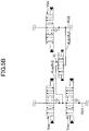
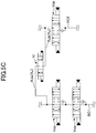
- the merging circuit RJ may be provided between the center bypass passage RC1 on the immediate upstream side of the auxiliary directional control valve Vop and the center bypass passage RC2 on the immediate upstream side of the directional control valve Vbk for the bucket as illustrated in FIG. 5B , or between the center bypass passage RC1 on the immediate downstream side of the auxiliary directional control valve Vop and the center bypass passage RC2 on the immediate downstream side of the directional control valve Vbk for the bucket as illustrated in FIG. 5C .
- the merging circuit RJ is used in the hydraulic circuit illustrated in FIG.
- the position of the auxiliary directional control valve Vop and the position of the directional control valve for swivel Vsw are mutually replaced to substantialize a positional relationship between the auxiliary directional control valve Vop and the directional control valve Vbk for the bucket.
- the merging circuit RJ of the embodiment controls the inflow direction of the pressurized oil inside the merging circuit RJ by changing the position of the spool in the merging directional control valve Vj. Further, the merging circuit RJ causes the pressurized oil generated by the pilot pump Pp ( FIG. 2 ) to be input to a pilot port (a control port) of the merging directional control valve Vj thereby controlling the position of the spool of the merging directional control valve Vj. Further, the merging circuit RJ uses the pressure of the pressurized oil inside the center bypass passage raised by reducing the opening area of the bleed-off valve Vbo to supply (merge) the pressurized oil into the other center bypass passage.
- pilot pressures (discharge pressures of the pilot pump Pp) A and B generated based on the operation information input in the construction machine 100 are input into control ports of the merging directional control valve Vj, respectively.
- the merging directional control valve Vj displaces the position (e.g., a position PA or PB in FIG. 5A ) of the spool in response to the pilot pressures A and B and bias forces of springs Spra and Sprb.
- the merging directional control valve Vj controls the inflow direction of the pressurized oil inside the merging circuit RJ.
- the merging circuit RJ of the embodiment prevents the pressurized oil from flowing in an inverse direction of the inflow direction using the check valve.
- the pressure of the pressurized oil inside the center bypass passage RC1 is raised and the position of the spool of the merging directional control valve Vj is displaced (Ra) to the position PA by decreasing the opening area of the bleed-off valve Vbo1.
- the pressure of the pressurized oil inside the center bypass passage RC2 is raised and the position of the spool of the merging directional control valve Vj is displaced (Rb) to the position PB by decreasing the opening area of the bleed-off valve Vbo2.
- the method of changing the position of the spool of the merging directional control valve Vj is not limited to the above direction (a pressurizing method).
- the merging directional control valve Vj may be substantialized by, for example, a combination of a solenoid valve (switched ON/OFF) and another mechanical structure (of hydraulic pilot).
- the position of the spool of the merging directional control valve Vj is not limited to the above position (the positions PA and PB).
- the merging directional control valve Vj may be structured to cancel a shock caused by merging by proportionally switching over the merging directional control valve Vj irrespective of the operation amount of the lever. Further, the check valve Vjc may not be built in the merging directional control valve Vj.
- a controller 30C ( FIG. 2 ) for controlling the entire operation of the construction machine 100 is installed in the control device 30 for the construction machine 100 of the embodiment.
- the controller 30C (the control device 30) is provided to instruct operations to components of the construction machine 100 and controls the operations of the components.
- the controller 30C (the control device 30) may be structured by an arithmetic processing unit including a central processing unit (CPU), a memory (a ROM, a RAM, or the like), and so on.
- the controller 30C of the embodiment controls the operation of the regulator R (R1, R2) based on operation information (the operation amount and the operation direction of the operation lever) input in the construction machine 100. With this, the discharge amount of the hydraulic pump P (P1, P2) is controlled by the regulator R.
- the remote control pressure is generated by the controller 30C using a remote control valve or the like based on the operation information input in the construction machine 100. Subsequently, the controller 30C inputs the generated remote control pressure to the directional control valve (e.g., Vt1) using the remote control circuit (not illustrated). With this, the directional control valve can control the operating oil supplied to the hydraulic actuator by switching the position of the spool using the input remote control pressure.
- the directional control valve e.g., Vt1
- the controller 30C controls the merging directional control valve Vj and the bleed-off valve Vbo based on the information input in the construction machine 100.
- the controller 30C controls the position of the spool of the merging directional control valve Vj and the opening degree (the opening area of) the bleed-off valve Vbo by controlling the discharge pressure of the pilot pump Pp, which is input in the merging directional control valve Vj and the bleed-off valve Vbo in response to, for example, a predetermined specific operating situation.
- the controller 30C can control the inflow direction of the merging circuit and the pressure of the pressurized oil which flows out.
- the control of the controller 30C is described in the following.
- the pressurized oil discharged from the hydraulic pump P can be supplied to the downstream side of the center bypass passage RC using the first internal passage without the bleed-off control using the directional control valve. Therefore, the pressure loss of the pressurized oil passing through the center bypass passage RC can be reduced.
- the hydraulic circuit 20 of the construction machine 100 and the control device 30 for the construction machine 100 of the embodiment in a case where the merging circuit is formed, it is unnecessary to provide an output port on the upstream side of the cut valve (the bleed-off valve), an input port on a side of merging with the center bypass passage, and an outer passage for connecting the output port with the input port.
- the hydraulic circuit can be miniaturized and the manufacture of the hydraulic circuit can be simplified. Further, according to the hydraulic circuit 20 of the construction machine 100 and the control device 30 for the construction machine 100 of the embodiment, because the inflow direction of the pressurized oil inside the merging circuit RJ can be controlled using the merging directional control valve Vj and the bleed-off valve Vbo, the pressurized oils can be bi-directionally merged in the multiple center bypass passages.
- the bleed-off control can be performed on the downstream side of the center bypass passage RC using the bleed-off valve Vbo arranged on the downstream side of the center bypass passage RC without the bleed-off control using the directional control valve (without providing the bleed opening in each directional control valve) . Therefore, according to the hydraulic circuit 20 and the control device 30 of the embodiment, because the opening area of the internal passage (e.g., the first internal passage) of the directional control valve can be increased in comparison with a case where the bleed-off control is performed using the multiple directional control valves, the pressure loss of the pressurized oil passing through the center bypass passage RC can be reduced.
- the internal passage e.g., the first internal passage
- the directional control valve can be miniaturized in comparison with a case where the bleed opening is formed in the directional control valve thereby facilitating the manufacture of the hydraulic circuit 20 and the control device 30.
- the directional control valve V can be miniaturized.
- the bleed-off valve Vbo can function as a cut valve (a neutral cut valve) for the merging circuit RJ, it is unnecessary to newly provide a cut valve.
- advantageous effects are given to the miniaturization of the entire size, the easiness in the manufacture, and the low cost of the construction machine 100.
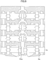
- FIG. 6 another example of the hydraulic circuit of the construction machine is illustrated.
- the bleed opening e.g., Sbo illustrated in FIG. 7
- the directional control valves e.g., Va1 or the like illustrated in FIG. 6 .
- the construction machine having the hydraulic circuit illustrated in FIG. 6 can perform the bleed-off control by changing the opening area of the bleed opening.
- the cut valve Vct and the output port Pout are provided to cause the pressurized oil to be flown out and the input port Pin is further provided to cause the pressurized oil to be flown in (merged). Therefore, there is case where the passage (for example, the passage connecting the output port Pout and the input port Pin) of the hydraulic circuit is complicated and the pressure loss of the pressurized oil increases. Further, in the hydraulic circuit illustrated in FIG. 6 , it is necessary to provide another set of the cut valve Vct and the output port Pout or the like in order to enable bi-directional merging of the pressurized oils. Said differently, the size of the hydraulic circuit in a case of FIG. 6 may become greater than the size of the hydraulic circuit of the present invention ( FIG. 4 ) because of the existence of the cut valve Vct, the output port Pout, or the like.
Landscapes
- Engineering & Computer Science (AREA)
- General Engineering & Computer Science (AREA)
- Mining & Mineral Resources (AREA)
- Civil Engineering (AREA)
- Structural Engineering (AREA)
- Physics & Mathematics (AREA)
- Fluid Mechanics (AREA)
- Mechanical Engineering (AREA)
- Fluid-Pressure Circuits (AREA)
- Operation Control Of Excavators (AREA)
Claims (8)
- Hydraulikschaltung für eine Baumaschine (100), die eine Vielzahl von zentralen Bypass- bzw. Umgehungsdurchlässen (RC, RC1, RC2) aufweist, in die ein unter Druck stehendes Öl geliefert wird, das von einer Vielzahl von hydraulischen Pumpen (P, P1, P2) ausgegeben wird, wobei die HydraulikschaltungFolgendes aufweist:eine Richtungssteuerventilgruppe (Gv), die eine Vielzahl von Richtungssteuerventilen (V, Va1, Va2, Vb1, Vb2, Vbk, Vsw, Vop, Vt1, Vt2, Vst) aufweist, die in Tandemanordnung mit den zentralen Umgehungsdurchlässen (RC, RC1, RC2) angeordnet sind;ein Überström- bzw. Entlastungsventil (Vbo), das auf einer nachgelagerten Seite jedes zentralen Umgehungsdurchlasses (RC, RC1, RC2) relativ zu der Richtungssteuerventilgruppe (Gv) angeordnet ist; undeine Zusammenführungsschaltung (RJ, RJa, RJb), die das unter Druck stehende Öl, das in einen zentralen Umgehungsdurchlass (RC, RC1, RC2) geliefert wird, und das unter Druck stehende Öl in einem anderen zentralen Umgehungsdurchlass der Vielzahl von zentralen Umgehungsdurchlässen (RC, RC1, RC2) zusammenführt,wobei jedes Richtungssteuerventil (V, Va1, Va2, Vb1, Vb2, Vbk, Vsw, Vop, Vt1, Vt2, Vst) Folgendes aufweist:einen ersten internen Durchlass (RV1), der das unter Druck stehende Öl, das in das Richtungssteuerventil geliefert wird, heraus in die zentralen Umgehungsdurchlässe (RC, RC1, RC2) strömt, undeinen zweiten internen Durchlass (RV2), der das unter Druck stehende Öl, das zu dem Richtungssteuerventil geliefert wird, an eine hydraulische Betätigungsvorrichtung der Baumaschine (100) liefert,wobei die zentralen Umgehungsdurchlässe (RC, RC1, RC2) und der erste interne Durchlass (RV1) parallele Durchlässe bilden, wobei der erste interne Durchlass (RV1) das unter Druck stehende Öl, das von der hydraulischen Pumpe (P, P1, P2) abgeführt wird, auf nachgelagerte Seiten der zentralen Umgehungsdurchlässe (RC, RC1, RC2) relativ zu dem Richtungssteuerventil herausströmt,
wobei das Entlastungsventil (Vbo) eine Entlastungssteuerung für das unter Druck stehende Öl ausführt, das durch den parallelen Durchlass geliefert wird, und zwar durch Verändern eines Öffnungsquerschnitts des Entlastungsventils (Vbo),
wobei die Zusammenführungsschaltung (RJ, RJa, RJb) ein zusammenführendes Richtungssteuerventil (Vj) aufweist, das eine Einströmrichtung des unter Druck stehenden Öls, das zusammengeführt werden soll, steuert. - Hydraulikschaltung für die Baumaschine gemäß Anspruch 1,
wobei der erste interne Durchlass (RV1) im Wesentlichen einen gleichen Durchlassquerschnitt aufweist, und zwar unabhängig von einer Position einesKolbens, der in jedem Richtungssteuerventil (V, Va1, Va2, Vb1, Vb2, Vbk, Vsw, Vop, Vt1, Vt2, Vst) enthalten ist und den parallelen Durchlass entsprechend dem Durchlassquerschnitt bildet,
wobei die Richtungssteuerventilgruppe (Gv) mit dem unter Druck stehenden Öl lediglich von dem parallelen Durchlass beliefert wird. - Hydraulikschaltung für die Baumaschine gemäß Anspruch 1,
wobei eine Anzahl der Vielzahl von hydraulischen Pumpen (P, P1, P2) zwei ist,
wobei eine Anzahl der Vielzahl von zentralen Umgehungsdurchlässen (RC, RC1, RC2) zwei ist,
wobei das zusammenführende Richtungssteuerventil (Vj) zu der Einströmrichtung umschaltet, um eines der unter Druck stehenden Öle, die jeweils an die zwei zentralen Umgehungsdurchlässe geliefert werden, an den zentralen Umgehungsdurchlass zu liefern, an den ein weiteres der unter Druck stehenden Öle geliefert wird. - Hydraulikschaltung für die Baumaschine gemäß Anspruch 1,
wobei die Zusammenführungsschaltung (RJ, RJa, RJb) ferner ein Absperr- bzw. Rückschlagventil (Vjc) zugehörig zu der Einströmrichtung aufweist, und verhindert, dass das unter Druck stehende Öl in einer umgekehrten Richtung zu der Einströmrichtung fließt. - Baumaschine (100), die eine Steuervorrichtung zur Steuerung der Hydraulikschaltung der Baumaschine (100) gemäß einem der Ansprüche 1-4 aufweist.
- Baumaschine gemäß Anspruch 5, wobei die Steuervorrichtung bewirkt, dass die Einströmrichtung ansprechend auf Betriebsinformation verändert wird, die in die Baumaschine (100) eingegeben wird.
- Baumaschine gemäß Anspruch 5 oder 6, wobei die Steuervorrichtung bewirkt, dass der Öffnungsquerschnitt des Entlastungsventils (Vbo) in einem Fall verringert wird, wo das unter Druck stehende Öl durch die Zusammenführungsschaltung (RJ, RJa, RJb) zusammengeführt wird.
- Baumaschine gemäß einem der Ansprüche 5-7, wobei die Steuervorrichtung bewirkt, dass die hydraulische Betätigungsvorrichtung zugehörig zu dem Richtungssteuerventil, in das das unter Druck stehende Öl, das zusammengeführt wird, geliefert wird, vorzugsweise betätigt wird.
Applications Claiming Priority (2)
| Application Number | Priority Date | Filing Date | Title |
|---|---|---|---|
| JP2012148928A JP5985276B2 (ja) | 2012-07-02 | 2012-07-02 | 建設機械の油圧回路及びその制御装置 |
| PCT/JP2013/060959 WO2014006950A1 (ja) | 2012-07-02 | 2013-04-11 | 建設機械の油圧回路及びその制御装置 |
Publications (3)
| Publication Number | Publication Date |
|---|---|
| EP2868930A1 EP2868930A1 (de) | 2015-05-06 |
| EP2868930A4 EP2868930A4 (de) | 2016-01-13 |
| EP2868930B1 true EP2868930B1 (de) | 2017-03-08 |
Family
ID=49881715
Family Applications (1)
| Application Number | Title | Priority Date | Filing Date |
|---|---|---|---|
| EP13813005.9A Active EP2868930B1 (de) | 2012-07-02 | 2013-04-11 | Hydraulikschaltung für eine baumaschine und steuerungsvorrichtung dafür |
Country Status (6)
| Country | Link |
|---|---|
| US (1) | US9725884B2 (de) |
| EP (1) | EP2868930B1 (de) |
| JP (1) | JP5985276B2 (de) |
| KR (1) | KR101642899B1 (de) |
| CN (1) | CN104246235B (de) |
| WO (1) | WO2014006950A1 (de) |
Families Citing this family (18)
| Publication number | Priority date | Publication date | Assignee | Title |
|---|---|---|---|---|
| EP3026181B1 (de) * | 2013-07-24 | 2018-11-14 | Volvo Construction Equipment AB | Hydraulikschaltung für eine baumaschine |
| CN106460880B (zh) * | 2014-12-16 | 2018-04-24 | Kyb株式会社 | 建筑机械的流体压控制装置 |
| KR101530886B1 (ko) * | 2015-02-09 | 2015-06-24 | 덕산네오룩스 주식회사 | 유기전기소자용 신규 화합물, 이를 이용한 유기전기소자 및 그 전자장치 |
| JP6456277B2 (ja) * | 2015-12-18 | 2019-01-23 | 日立建機株式会社 | 建設機械 |
| JP6304273B2 (ja) * | 2016-02-05 | 2018-04-04 | コベルコ建機株式会社 | 作業機械の油圧駆動装置 |
| JP6840756B2 (ja) | 2016-07-29 | 2021-03-10 | 住友建機株式会社 | ショベル、ショベル用コントロールバルブ |
| WO2017014324A1 (ja) * | 2016-07-29 | 2017-01-26 | 株式会社小松製作所 | 制御システム、作業機械、及び制御方法 |
| DE112016006779B4 (de) * | 2016-09-21 | 2022-06-09 | Komatsu Ltd. | Arbeitsfahrzeug und Hydraulik-Steuerungsverfahren |
| GB2554682B (en) * | 2016-10-03 | 2022-01-19 | Bamford Excavators Ltd | Hydraulic systems for construction machinery |
| GB2554683B (en) * | 2016-10-03 | 2022-01-26 | Bamford Excavators Ltd | Hydraulic systems for construction machinery |
| JP7034686B2 (ja) | 2017-11-30 | 2022-03-14 | キヤノンメディカルシステムズ株式会社 | 超音波診断装置、医用画像処理装置及びそのプログラム |
| CN111433465B (zh) * | 2017-12-07 | 2022-08-16 | 住友建机株式会社 | 挖土机 |
| JP7227830B2 (ja) * | 2019-03-30 | 2023-02-22 | 住友建機株式会社 | ショベル |
| US11624452B2 (en) | 2019-04-12 | 2023-04-11 | Barko Hydraulics, LLC | System for adjusting rate of spool centering in a pilot-controlled hydraulic spool valve |
| JP7182579B2 (ja) * | 2020-03-27 | 2022-12-02 | 日立建機株式会社 | 作業機械 |
| US11001989B1 (en) * | 2020-03-30 | 2021-05-11 | Caterpillar Inc. | Electrical control of a hydraulic system |
| JP7472321B2 (ja) * | 2020-12-24 | 2024-04-22 | 日立建機株式会社 | 作業機械 |
| US12352014B2 (en) | 2023-12-04 | 2025-07-08 | Caterpillar Inc. | Enhanced electrical control of a hydraulic system |
Family Cites Families (17)
| Publication number | Priority date | Publication date | Assignee | Title |
|---|---|---|---|---|
| JPS6138204A (ja) | 1984-07-30 | 1986-02-24 | Toshiba Mach Co Ltd | 多連油圧切換弁のための多連パイロツト弁 |
| JP2740223B2 (ja) | 1989-01-09 | 1998-04-15 | 日立建機株式会社 | 弁装置 |
| JPH02248706A (ja) * | 1989-03-22 | 1990-10-04 | Komatsu Ltd | 油圧回路 |
| JP3501902B2 (ja) * | 1996-06-28 | 2004-03-02 | コベルコ建機株式会社 | 建設機械の制御回路 |
| JP3643193B2 (ja) * | 1996-11-20 | 2005-04-27 | コベルコ建機株式会社 | 油圧モータの制御装置 |
| US5941155A (en) * | 1996-11-20 | 1999-08-24 | Kabushiki Kaisha Kobe Seiko Sho | Hydraulic motor control system |
| JPH11107328A (ja) * | 1997-10-02 | 1999-04-20 | Kobe Steel Ltd | 油圧ショベルの油圧制御装置 |
| JP3699587B2 (ja) * | 1998-03-06 | 2005-09-28 | 東芝機械株式会社 | 多連油圧バルブ |
| JP3948122B2 (ja) * | 1998-06-22 | 2007-07-25 | コベルコクレーン株式会社 | 油圧アクチュエータの制御装置 |
| JP3943779B2 (ja) * | 1999-01-19 | 2007-07-11 | 日立建機株式会社 | 土木・建設機械の油圧駆動装置 |
| JP4096901B2 (ja) * | 2004-03-17 | 2008-06-04 | コベルコ建機株式会社 | 作業機械の油圧制御装置 |
| JP4578207B2 (ja) | 2004-11-08 | 2010-11-10 | カヤバ工業株式会社 | 弁装置 |
| JP2007120004A (ja) * | 2005-10-24 | 2007-05-17 | Kobelco Contstruction Machinery Ltd | 作業機械の油圧制御装置 |
| JP4232784B2 (ja) * | 2006-01-20 | 2009-03-04 | コベルコ建機株式会社 | 作業機械の油圧制御装置 |
| JP4353190B2 (ja) * | 2006-02-27 | 2009-10-28 | コベルコ建機株式会社 | 建設機械の油圧回路 |
| US7614225B2 (en) * | 2006-04-18 | 2009-11-10 | Volvo Construction Equipment Holding Sweden Ab | Straight traveling hydraulic circuit |
| EP2157245B1 (de) * | 2008-08-21 | 2021-03-17 | Volvo Construction Equipment AB | Hydrauliksystem für ein Baugerät |
-
2012
- 2012-07-02 JP JP2012148928A patent/JP5985276B2/ja not_active Expired - Fee Related
-
2013
- 2013-04-11 KR KR1020147028305A patent/KR101642899B1/ko not_active Expired - Fee Related
- 2013-04-11 WO PCT/JP2013/060959 patent/WO2014006950A1/ja not_active Ceased
- 2013-04-11 EP EP13813005.9A patent/EP2868930B1/de active Active
- 2013-04-11 CN CN201380020035.5A patent/CN104246235B/zh active Active
-
2014
- 2014-10-28 US US14/525,322 patent/US9725884B2/en active Active
Non-Patent Citations (1)
| Title |
|---|
| None * |
Also Published As
| Publication number | Publication date |
|---|---|
| EP2868930A1 (de) | 2015-05-06 |
| CN104246235A (zh) | 2014-12-24 |
| US20150040552A1 (en) | 2015-02-12 |
| KR101642899B1 (ko) | 2016-07-26 |
| WO2014006950A1 (ja) | 2014-01-09 |
| JP5985276B2 (ja) | 2016-09-06 |
| CN104246235B (zh) | 2017-07-14 |
| US9725884B2 (en) | 2017-08-08 |
| EP2868930A4 (de) | 2016-01-13 |
| JP2014009794A (ja) | 2014-01-20 |
| KR20140138267A (ko) | 2014-12-03 |
Similar Documents
| Publication | Publication Date | Title |
|---|---|---|
| US9725884B2 (en) | Hydraulic circuit for construction machine and control device for same | |
| EP2863065B1 (de) | Baumaschinenhydraulikkreis und steuerungsvorrichtung dafür | |
| KR101820324B1 (ko) | 파이프 레이어용 유압회로 | |
| EP2863066B1 (de) | Hydraulikkreis für baumaschine | |
| US9657461B2 (en) | Hydraulic circuit for construction machine and control device for same | |
| CN108368691B (zh) | 工程机械的液压控制装置及液压控制方法 | |
| US9821840B2 (en) | Hydraulic control device and construction machinery including same | |
| US10001147B2 (en) | Independent metering valve priority in open center hydraulic system | |
| JP2017115992A (ja) | 作業機の油圧システム | |
| EP2602491A1 (de) | Baumaschine mit hydraulikkreislauf | |
| CN109563695B (zh) | 挖土机、挖土机用控制阀门 | |
| KR101080173B1 (ko) | 복수개의 컨트롤밸브유닛들이 결합된 굴삭기용 메인컨트롤밸브어셈블리 | |
| JP6453820B2 (ja) | 建設機械用方向制御弁グループ | |
| US12497760B2 (en) | Hydraulic drive apparatus | |
| KR102946030B1 (ko) | 유체 제어 장치, 건설 기계 및 유체 제어 장치의 제어 방법 | |
| KR20190115050A (ko) | 방향 전환 밸브 | |
| JP6763006B2 (ja) | ショベル及び建設機械用方向制御弁グループ | |
| JP2022075402A (ja) | 液圧駆動システム | |
| JP7492815B2 (ja) | 流体制御弁、流体システム、建設機械および制御方法 | |
| CN118843750A (zh) | 液压驱动装置 | |
| CN121773287A (zh) | 液压阀装置 | |
| JP5934669B2 (ja) | 建設機械の油圧駆動装置 | |
| JP2021143726A (ja) | 建設機械の油圧制御回路 |
Legal Events
| Date | Code | Title | Description |
|---|---|---|---|
| PUAI | Public reference made under article 153(3) epc to a published international application that has entered the european phase |
Free format text: ORIGINAL CODE: 0009012 |
|
| 17P | Request for examination filed |
Effective date: 20141219 |
|
| AK | Designated contracting states |
Kind code of ref document: A1 Designated state(s): AL AT BE BG CH CY CZ DE DK EE ES FI FR GB GR HR HU IE IS IT LI LT LU LV MC MK MT NL NO PL PT RO RS SE SI SK SM TR |
|
| AX | Request for extension of the european patent |
Extension state: BA ME |
|
| DAX | Request for extension of the european patent (deleted) | ||
| RA4 | Supplementary search report drawn up and despatched (corrected) |
Effective date: 20151214 |
|
| RIC1 | Information provided on ipc code assigned before grant |
Ipc: F15B 11/02 20060101AFI20151208BHEP Ipc: E02F 9/22 20060101ALI20151208BHEP Ipc: F15B 11/17 20060101ALI20151208BHEP |
|
| 17Q | First examination report despatched |
Effective date: 20160105 |
|
| GRAP | Despatch of communication of intention to grant a patent |
Free format text: ORIGINAL CODE: EPIDOSNIGR1 |
|
| INTG | Intention to grant announced |
Effective date: 20160907 |
|
| GRAS | Grant fee paid |
Free format text: ORIGINAL CODE: EPIDOSNIGR3 |
|
| GRAA | (expected) grant |
Free format text: ORIGINAL CODE: 0009210 |
|
| RIN1 | Information on inventor provided before grant (corrected) |
Inventor name: HASHIMOTO, HIROFUMI |
|
| AK | Designated contracting states |
Kind code of ref document: B1 Designated state(s): AL AT BE BG CH CY CZ DE DK EE ES FI FR GB GR HR HU IE IS IT LI LT LU LV MC MK MT NL NO PL PT RO RS SE SI SK SM TR |
|
| REG | Reference to a national code |
Ref country code: GB Ref legal event code: FG4D |
|
| REG | Reference to a national code |
Ref country code: CH Ref legal event code: EP Ref country code: AT Ref legal event code: REF Ref document number: 873796 Country of ref document: AT Kind code of ref document: T Effective date: 20170315 |
|
| REG | Reference to a national code |
Ref country code: IE Ref legal event code: FG4D |
|
| REG | Reference to a national code |
Ref country code: DE Ref legal event code: R096 Ref document number: 602013018386 Country of ref document: DE |
|
| REG | Reference to a national code |
Ref country code: LT Ref legal event code: MG4D |
|
| REG | Reference to a national code |
Ref country code: NL Ref legal event code: MP Effective date: 20170308 |
|
| PG25 | Lapsed in a contracting state [announced via postgrant information from national office to epo] |
Ref country code: GR Free format text: LAPSE BECAUSE OF FAILURE TO SUBMIT A TRANSLATION OF THE DESCRIPTION OR TO PAY THE FEE WITHIN THE PRESCRIBED TIME-LIMIT Effective date: 20170609 Ref country code: LT Free format text: LAPSE BECAUSE OF FAILURE TO SUBMIT A TRANSLATION OF THE DESCRIPTION OR TO PAY THE FEE WITHIN THE PRESCRIBED TIME-LIMIT Effective date: 20170308 Ref country code: NO Free format text: LAPSE BECAUSE OF FAILURE TO SUBMIT A TRANSLATION OF THE DESCRIPTION OR TO PAY THE FEE WITHIN THE PRESCRIBED TIME-LIMIT Effective date: 20170608 Ref country code: FI Free format text: LAPSE BECAUSE OF FAILURE TO SUBMIT A TRANSLATION OF THE DESCRIPTION OR TO PAY THE FEE WITHIN THE PRESCRIBED TIME-LIMIT Effective date: 20170308 Ref country code: HR Free format text: LAPSE BECAUSE OF FAILURE TO SUBMIT A TRANSLATION OF THE DESCRIPTION OR TO PAY THE FEE WITHIN THE PRESCRIBED TIME-LIMIT Effective date: 20170308 |
|
| REG | Reference to a national code |
Ref country code: AT Ref legal event code: MK05 Ref document number: 873796 Country of ref document: AT Kind code of ref document: T Effective date: 20170308 |
|
| PG25 | Lapsed in a contracting state [announced via postgrant information from national office to epo] |
Ref country code: BG Free format text: LAPSE BECAUSE OF FAILURE TO SUBMIT A TRANSLATION OF THE DESCRIPTION OR TO PAY THE FEE WITHIN THE PRESCRIBED TIME-LIMIT Effective date: 20170608 Ref country code: RS Free format text: LAPSE BECAUSE OF FAILURE TO SUBMIT A TRANSLATION OF THE DESCRIPTION OR TO PAY THE FEE WITHIN THE PRESCRIBED TIME-LIMIT Effective date: 20170308 Ref country code: SE Free format text: LAPSE BECAUSE OF FAILURE TO SUBMIT A TRANSLATION OF THE DESCRIPTION OR TO PAY THE FEE WITHIN THE PRESCRIBED TIME-LIMIT Effective date: 20170308 Ref country code: ES Free format text: LAPSE BECAUSE OF FAILURE TO SUBMIT A TRANSLATION OF THE DESCRIPTION OR TO PAY THE FEE WITHIN THE PRESCRIBED TIME-LIMIT Effective date: 20170308 Ref country code: LV Free format text: LAPSE BECAUSE OF FAILURE TO SUBMIT A TRANSLATION OF THE DESCRIPTION OR TO PAY THE FEE WITHIN THE PRESCRIBED TIME-LIMIT Effective date: 20170308 |
|
| PG25 | Lapsed in a contracting state [announced via postgrant information from national office to epo] |
Ref country code: NL Free format text: LAPSE BECAUSE OF FAILURE TO SUBMIT A TRANSLATION OF THE DESCRIPTION OR TO PAY THE FEE WITHIN THE PRESCRIBED TIME-LIMIT Effective date: 20170308 |
|
| PG25 | Lapsed in a contracting state [announced via postgrant information from national office to epo] |
Ref country code: RO Free format text: LAPSE BECAUSE OF FAILURE TO SUBMIT A TRANSLATION OF THE DESCRIPTION OR TO PAY THE FEE WITHIN THE PRESCRIBED TIME-LIMIT Effective date: 20170308 Ref country code: SK Free format text: LAPSE BECAUSE OF FAILURE TO SUBMIT A TRANSLATION OF THE DESCRIPTION OR TO PAY THE FEE WITHIN THE PRESCRIBED TIME-LIMIT Effective date: 20170308 Ref country code: AT Free format text: LAPSE BECAUSE OF FAILURE TO SUBMIT A TRANSLATION OF THE DESCRIPTION OR TO PAY THE FEE WITHIN THE PRESCRIBED TIME-LIMIT Effective date: 20170308 Ref country code: CZ Free format text: LAPSE BECAUSE OF FAILURE TO SUBMIT A TRANSLATION OF THE DESCRIPTION OR TO PAY THE FEE WITHIN THE PRESCRIBED TIME-LIMIT Effective date: 20170308 Ref country code: EE Free format text: LAPSE BECAUSE OF FAILURE TO SUBMIT A TRANSLATION OF THE DESCRIPTION OR TO PAY THE FEE WITHIN THE PRESCRIBED TIME-LIMIT Effective date: 20170308 |
|
| PG25 | Lapsed in a contracting state [announced via postgrant information from national office to epo] |
Ref country code: PL Free format text: LAPSE BECAUSE OF FAILURE TO SUBMIT A TRANSLATION OF THE DESCRIPTION OR TO PAY THE FEE WITHIN THE PRESCRIBED TIME-LIMIT Effective date: 20170308 Ref country code: IS Free format text: LAPSE BECAUSE OF FAILURE TO SUBMIT A TRANSLATION OF THE DESCRIPTION OR TO PAY THE FEE WITHIN THE PRESCRIBED TIME-LIMIT Effective date: 20170708 Ref country code: PT Free format text: LAPSE BECAUSE OF FAILURE TO SUBMIT A TRANSLATION OF THE DESCRIPTION OR TO PAY THE FEE WITHIN THE PRESCRIBED TIME-LIMIT Effective date: 20170710 Ref country code: SM Free format text: LAPSE BECAUSE OF FAILURE TO SUBMIT A TRANSLATION OF THE DESCRIPTION OR TO PAY THE FEE WITHIN THE PRESCRIBED TIME-LIMIT Effective date: 20170308 |
|
| REG | Reference to a national code |
Ref country code: CH Ref legal event code: PL |
|
| REG | Reference to a national code |
Ref country code: DE Ref legal event code: R097 Ref document number: 602013018386 Country of ref document: DE |
|
| PLBE | No opposition filed within time limit |
Free format text: ORIGINAL CODE: 0009261 |
|
| STAA | Information on the status of an ep patent application or granted ep patent |
Free format text: STATUS: NO OPPOSITION FILED WITHIN TIME LIMIT |
|
| REG | Reference to a national code |
Ref country code: IE Ref legal event code: MM4A |
|
| REG | Reference to a national code |
Ref country code: FR Ref legal event code: ST Effective date: 20171229 |
|
| PG25 | Lapsed in a contracting state [announced via postgrant information from national office to epo] |
Ref country code: FR Free format text: LAPSE BECAUSE OF NON-PAYMENT OF DUE FEES Effective date: 20170509 Ref country code: DK Free format text: LAPSE BECAUSE OF FAILURE TO SUBMIT A TRANSLATION OF THE DESCRIPTION OR TO PAY THE FEE WITHIN THE PRESCRIBED TIME-LIMIT Effective date: 20170308 Ref country code: MC Free format text: LAPSE BECAUSE OF FAILURE TO SUBMIT A TRANSLATION OF THE DESCRIPTION OR TO PAY THE FEE WITHIN THE PRESCRIBED TIME-LIMIT Effective date: 20170308 |
|
| 26N | No opposition filed |
Effective date: 20171211 |
|
| PG25 | Lapsed in a contracting state [announced via postgrant information from national office to epo] |
Ref country code: LU Free format text: LAPSE BECAUSE OF NON-PAYMENT OF DUE FEES Effective date: 20170411 Ref country code: LI Free format text: LAPSE BECAUSE OF NON-PAYMENT OF DUE FEES Effective date: 20170430 Ref country code: CH Free format text: LAPSE BECAUSE OF NON-PAYMENT OF DUE FEES Effective date: 20170430 Ref country code: SI Free format text: LAPSE BECAUSE OF FAILURE TO SUBMIT A TRANSLATION OF THE DESCRIPTION OR TO PAY THE FEE WITHIN THE PRESCRIBED TIME-LIMIT Effective date: 20170308 |
|
| REG | Reference to a national code |
Ref country code: BE Ref legal event code: MM Effective date: 20170430 |
|
| PG25 | Lapsed in a contracting state [announced via postgrant information from national office to epo] |
Ref country code: IE Free format text: LAPSE BECAUSE OF NON-PAYMENT OF DUE FEES Effective date: 20170411 |
|
| PG25 | Lapsed in a contracting state [announced via postgrant information from national office to epo] |
Ref country code: BE Free format text: LAPSE BECAUSE OF NON-PAYMENT OF DUE FEES Effective date: 20170430 |
|
| PG25 | Lapsed in a contracting state [announced via postgrant information from national office to epo] |
Ref country code: MT Free format text: LAPSE BECAUSE OF NON-PAYMENT OF DUE FEES Effective date: 20170411 |
|
| PG25 | Lapsed in a contracting state [announced via postgrant information from national office to epo] |
Ref country code: HU Free format text: LAPSE BECAUSE OF FAILURE TO SUBMIT A TRANSLATION OF THE DESCRIPTION OR TO PAY THE FEE WITHIN THE PRESCRIBED TIME-LIMIT; INVALID AB INITIO Effective date: 20130411 |
|
| PG25 | Lapsed in a contracting state [announced via postgrant information from national office to epo] |
Ref country code: CY Free format text: LAPSE BECAUSE OF FAILURE TO SUBMIT A TRANSLATION OF THE DESCRIPTION OR TO PAY THE FEE WITHIN THE PRESCRIBED TIME-LIMIT Effective date: 20170308 |
|
| PG25 | Lapsed in a contracting state [announced via postgrant information from national office to epo] |
Ref country code: MK Free format text: LAPSE BECAUSE OF FAILURE TO SUBMIT A TRANSLATION OF THE DESCRIPTION OR TO PAY THE FEE WITHIN THE PRESCRIBED TIME-LIMIT Effective date: 20170308 |
|
| PG25 | Lapsed in a contracting state [announced via postgrant information from national office to epo] |
Ref country code: TR Free format text: LAPSE BECAUSE OF FAILURE TO SUBMIT A TRANSLATION OF THE DESCRIPTION OR TO PAY THE FEE WITHIN THE PRESCRIBED TIME-LIMIT Effective date: 20170308 |
|
| PG25 | Lapsed in a contracting state [announced via postgrant information from national office to epo] |
Ref country code: AL Free format text: LAPSE BECAUSE OF FAILURE TO SUBMIT A TRANSLATION OF THE DESCRIPTION OR TO PAY THE FEE WITHIN THE PRESCRIBED TIME-LIMIT Effective date: 20170308 |
|
| PGFP | Annual fee paid to national office [announced via postgrant information from national office to epo] |
Ref country code: IT Payment date: 20250320 Year of fee payment: 13 Ref country code: GB Payment date: 20250227 Year of fee payment: 13 |
|
| PGFP | Annual fee paid to national office [announced via postgrant information from national office to epo] |
Ref country code: DE Payment date: 20250305 Year of fee payment: 13 |