EP2869035B1 - Système de mesure de position et procédé de régulation pour moteurs linéaires concaténés - Google Patents
Système de mesure de position et procédé de régulation pour moteurs linéaires concaténés Download PDFInfo
- Publication number
- EP2869035B1 EP2869035B1 EP13190680.2A EP13190680A EP2869035B1 EP 2869035 B1 EP2869035 B1 EP 2869035B1 EP 13190680 A EP13190680 A EP 13190680A EP 2869035 B1 EP2869035 B1 EP 2869035B1
- Authority
- EP
- European Patent Office
- Prior art keywords
- receiver
- carriage
- measuring system
- position sensor
- carriages
- Prior art date
- Legal status (The legal status is an assumption and is not a legal conclusion. Google has not performed a legal analysis and makes no representation as to the accuracy of the status listed.)
- Active
Links
Images

Classifications
-
- G—PHYSICS
- G01—MEASURING; TESTING
- G01D—MEASURING NOT SPECIALLY ADAPTED FOR A SPECIFIC VARIABLE; ARRANGEMENTS FOR MEASURING TWO OR MORE VARIABLES NOT COVERED IN A SINGLE OTHER SUBCLASS; TARIFF METERING APPARATUS; MEASURING OR TESTING NOT OTHERWISE PROVIDED FOR
- G01D5/00—Mechanical means for transferring the output of a sensing member; Means for converting the output of a sensing member to another variable where the form or nature of the sensing member does not constrain the means for converting; Transducers not specially adapted for a specific variable
- G01D5/48—Mechanical means for transferring the output of a sensing member; Means for converting the output of a sensing member to another variable where the form or nature of the sensing member does not constrain the means for converting; Transducers not specially adapted for a specific variable using wave or particle radiation means
- G01D5/485—Mechanical means for transferring the output of a sensing member; Means for converting the output of a sensing member to another variable where the form or nature of the sensing member does not constrain the means for converting; Transducers not specially adapted for a specific variable using wave or particle radiation means using magnetostrictive devices
-
- H—ELECTRICITY
- H02—GENERATION; CONVERSION OR DISTRIBUTION OF ELECTRIC POWER
- H02K—DYNAMO-ELECTRIC MACHINES
- H02K11/00—Structural association of dynamo-electric machines with electric components or with devices for shielding, monitoring or protection
- H02K11/20—Structural association of dynamo-electric machines with electric components or with devices for shielding, monitoring or protection for measuring, monitoring, testing, protecting or switching
- H02K11/21—Devices for sensing speed or position, or actuated thereby
- H02K11/215—Magnetic effect devices, e.g. Hall-effect or magneto-resistive elements
-
- H—ELECTRICITY
- H02—GENERATION; CONVERSION OR DISTRIBUTION OF ELECTRIC POWER
- H02K—DYNAMO-ELECTRIC MACHINES
- H02K41/00—Propulsion systems in which a rigid body is moved along a path due to dynamo-electric interaction between the body and a magnetic field travelling along the path
- H02K41/02—Linear motors; Sectional motors
- H02K41/03—Synchronous motors; Motors moving step by step; Reluctance motors
- H02K41/031—Synchronous motors; Motors moving step by step; Reluctance motors of the permanent magnet type
- H02K41/033—Synchronous motors; Motors moving step by step; Reluctance motors of the permanent magnet type with armature and magnets on one member, the other member being a flux distributor
Definitions
- Linear motors are known per se. Also linked linear motors are known. A typical example application of a linked linear motor are so-called sorters in which the individual motor links are mounted on carriers coupled to a chain. Typically, the carriers are closed in an infinite loop.
- a linear motor in which either the primary part or the secondary part along the respective route is divided into individual members.
- the links are mechanically interconnected, for example, via a coupling.
- the coupling creates gaps between the motor links and gaps in the magnetic pole sequence.
- encoder-based control methods For optimum control of synchronous motors with good synchronization, encoder-based control methods have, in principle, the advantage over sensorless methods, since the gaps between the links have an unfavorable effect on the motor model-based calculation of the pole position and the speed in the case of sensorless control methods.
- a method is known in which for detection in a route in each route segment a measuring rod functioning as a receiver of the local position measuring system is arranged thereon and a carriage moved along the path has at least two marking magnets as the transmitter cooperating with the receiver. Normally, the position information taken with the first front marker magnet is used. When crossing a border between two measuring rods, the rear marking magnet is used to acquire the position information at a certain distance from the front end of the measuring rod.
- the linear motor comprises at least one primary part and at least two coupled secondary parts or at least one secondary part and at least two coupled primary parts.
- the movable motor members so the coupled primary or secondary parts, each associated with a carriage of a driven with the linear motor carriage chain, the entirety of the carriage during operation of the linear motor along a driving distance is movable.
- Each car is assigned a position transmitter.
- the route is assigned a sensitive for the position sensor receiver.
- the receiver is aligned longitudinally to the route and is located, for example, next to the stationary motor part, ie movable motor links in the form of at least two chained secondary parts next to the at least one primary part or moving motor links in the form of at least two chained primary parts next to the at least one secondary part.
- a position information can be generated or output, which encodes a relative position of the position sensor to the receiver.
- the position information is formed as a numerical value number, which can be generated by the relative position of the position input (20) to the receiver (22).
- the receiver has a length of each carriage, measured in the direction of travel of the car, of at least equal length.
- the receiver has a greater length compared to a length of each carriage measured in the direction of travel of the car, it is ensured that the position transmitter of at least one carriage is always located in a detection range of the receiver.
- a suitable for controlled control of the concatenated linear motor position information is always available, which is not only independent of any fluctuating width of the gaps between the chained primary or secondary parts, but also a hitherto often observed Adding up the resulting errors due to such gaps avoids.
- two position information results, of which only the numerically smaller position information is used. This ensures mathematically simple conditions. A particular constellation in which this is exploited is described below.
- the position measuring system ensures that in more than one position information always only the numerically smallest position information is used by the position measuring system transmits only the numerically smallest position information to a control / regulating device of the concatenated linear motor. The latter minimizes the requirements for an interface between the position measuring system and the control / regulating device.
- a receiver and position sensor are a magnetostrictive transducer or a permanent magnet into consideration.
- a receiver / displacement transducer has the advantage that its generation of position information based on a position of the permanent magnet relative to its longitudinal extent is not influenced by the magnetic fields emanating from the linked linear motor.
- a receiver-position encoder combination comes into consideration, which is based on a capacitive, optical, magnetic, resistive, etc. operating principle.
- the position sensors are each arranged in the middle of a primary or secondary part associated with a car. This ensures adequate coverage of the respective moving and stationary motor links as and as long as the locator is within the detection range of the receiver.
- the abovementioned object is also achieved with a control method for a linked linear motor, which is characterized in that an actual value for a control of the linked linear motor is determined by means of a position measuring system of the type described here and below.
- a position measuring system of the type described here and below.
- the position information obtained from the position measuring system is mapped to an angle range of 0 ° to 359 ° and the motor control is like the control in a rotating synchronous motor.
- the motor control is like the control in a rotating synchronous motor.
- position information in a range of 0 ° to a multiple of 360 ° corresponding to the number of carriages is detected.
- At least one of the carriages is provided with an automatically interrogatable identifier, in particular an RFID tag, it is possible to determine an absolute position after a passage in a closed chain of the movable motor members.
- FIG. 1 schematically shows a simplified linear motor 10 with a stationary primary part 12 and a movable secondary part 14.
- a linear motor 10 may comprise a plurality of movable secondaries 14, which may be used, for example, in a sorter application as the basis for individual carriages 16 (FIG. FIG. 2 ) act.
- the primary part 12 comprises permanent magnets (not shown) in a manner known per se and is integrated in the respective driving route (travel path) 18.
- the or each secondary part 14, in a manner also known per se, has a toothed iron core (not shown) oriented in the direction of movement. The direction of movement is in FIG. 1 illustrated with the left-pointing block arrow.
- the mention of the primary part 12 as stationary is to be understood as an example only. In fact, it is irrelevant whether chained primary parts 12 or chained secondary parts 14 function as movable motor links and thus as the basis for the carriages 16.
- the description of the embodiment is - without waiving a broader generality - continued on the basis of a stationary primary part 12 and a plurality of movable and chained secondary parts 14.
- FIG. 1 acting as the basis for a carriage 16 secondary part 14 includes a position sensor 20 and that the route 18, in particular the primary part 12, an associated with the position sensor 20, elongated and along the route 18 oriented receiver 22 is associated.
- the primary part 12 and the receiver 22 are in parallel alignment next to each other.
- the receiver 22 is, for example, a basically known magnetostrictive displacement transducer.
- a cooperating with such a receiver 22 position sensor 20 is a mounted on each carriage 16 in particular centrally to the local secondary part 14 permanent magnet.
- a description of the function of a magnetostrictive transducer does not seem necessary here. Instead, reference is made to the extent relevant literature.
- a receiver 22 in the form of a magnetostrictive displacement sensor for example, a sensor offered by the company MTS Systems Corporation under the brand "Temposonics" is considered.
- the advantage of using a magnetostrictive displacement transducer as a receiver 22 is, above all, that its position evaluation is apparently independent of the magnetic field emanating from the linear motor 10, at least it has been found that stray fields emanating from the linear motor 10 are not critical due to the distance. Further advantages are a simple transmitter (position sensor 20), namely a transmitter in the form of a permanent magnet, the insensitivity of the position transmitter-receiver combination, against influences that are often to be expected in industrial use, for example, insensitivity to dust, oil and the like, as well as a greater tolerance than, for example, optical encoders with regard to the distance (air gap) between the position sensor and the receiver.
- the representation in FIG. 2 is a snapshot of the movement of the carriage 16 at a first time.
- the representation in FIG. 3 is a snapshot of the movement of the carriage 16 at a later, second time.
- the position information supplied by the receiver 22 ("pos1") to interpret as an absolute angular position in a control of a rotating synchronous motor.
- the maximum value "max” is not reached, if previously the position sensor 20 of the subsequent in the chain Car 16 enters the detection range of the receiver 22.
- a control as it is known from a rotating synchronous motor, is then particularly simple if the angular position is assigned to the minimum value 0 ° and the maximum actually achieved in each case the angular position 359 °. Then, a travel path between two position encoders 20 corresponds to a virtual encoder revolution.
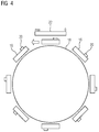
- the representation in FIG. 4 shows a situation with a plurality of carriages 16 coupled to a closed link chain.
- the carriages 16 are provided with an automatically interrogatable identifier.
- RFID tags and a corresponding reader both not shown
- any chain dimension errors can also be eliminated.
- only one of the carriages 16 is provided with an automatically interrogatable identifier.
Landscapes
- Engineering & Computer Science (AREA)
- Power Engineering (AREA)
- Physics & Mathematics (AREA)
- Microelectronics & Electronic Packaging (AREA)
- Chemical & Material Sciences (AREA)
- Combustion & Propulsion (AREA)
- Electromagnetism (AREA)
- General Physics & Mathematics (AREA)
- Control Of Linear Motors (AREA)
- Control Of Conveyors (AREA)
Claims (7)
- Système de mesure de position pour des moteurs ( 10 ) linéaires concaténés,- dans lequel le moteur ( 10 ) linéaire comprend au moins une partie ( 12 ) primaire et au moins deux parties ( 14 ) secondaires couplées ou au moins une partie ( 14 ) secondaire et au moins deux parties ( 12 ) primaires couplées,- dans lequel les parties ( 12, 14 ) primaires ou secondaires couplées sont associées respectivement à un chariot ( 16 ) d'une chaîne de chariot et dans lequel l'ensemble des chariots ( 16 ) couplés est, lorsque le moteur ( 10 ) linéaire est en fonctionnement, mobile le long d'une voie ( 18 ) de circulation,- dans lequel un indicateur ( 20 ) de position est associé à chaque chariot ( 16 ),- dans lequel un récepteur ( 22 ) sensible à l'indicateur ( 20 ) de position est associé à la voie ( 18 ) de circulation,- dans lequel le récepteur ( 22 ) est orienté en long par rapport à la voie ( 18 ) de circulation,- dans lequel il peut être créé ou émis, à l'aide du récepteur ( 22 ), une information de position, qui code une position relative de l'indicateur ( 20 ) de position par rapport au récepteur ( 22 ), et dans lequel l'information de position est constituée sous la forme d'une valeur numérique, qui peut être produite par la position relative de l'indicateur ( 20 ) de position par rapport au récepteur ( 22 ) et- dans lequel le récepteur ( 22 ) a, par rapport à une longueur de chaque chariot ( 16 ) mesurée dans le sens de marche du chariot ( 16 ), une longueur au moins aussi grande, caractérisé- en ce que, dans le cas de deux indicateurs ( 20 ) de position se trouvant en même temps dans la portée du récepteur ( 22 ), à savoir un premier indicateur ( 20 ) de position d'un premier chariot ( 16 ) et un deuxième indicateur ( 20 ) de position d'un deuxième chariot ( 16 ) couplé au premier chariot, il s'ensuit deux informations de position et seule l'information de position la plus petite numériquement est utilisée et- en ce que les informations de position obtenues par le système de mesure de position sont reproduites sur une plage angulaire de 0° à 359°.
- Système de mesure de position suivant la revendication 1, dans lequel le récepteur ( 22 ) est un capteur de déplacement magnétostrictif et l'indicateur ( 20 ) de position un aimant permanent.
- Système de mesure de position suivant l'une des revendications 1 à 2, dans lequel l'indicateur ( 20 ) de position est mis au milieu de la partie ( 12, 14 ) primaire ou secondaire associée au chariot ( 16 ).
- Procédé de régulation pour un moteur ( 10 ) linéaire concaténé, une valeur réelle pour une régulation du moteur ( 10 ) linéaire concaténé étant déterminée au moyen d'un système de mesure de position suivant l'une des revendications 1 à 3 et la régulation du moteur s'effectuant comme la régulation pour un moteur synchrone tournant.
- Procédé de régulation suivant la revendication 4, dans lequel, pour obtenir une information sur la position absolue du moteur ( 10 ) linéaire, on relève une information de position dans une plage de 0° jusqu'à un multiple de 360° correspondant au nombre des chariots ( 16 ).
- Procédé de régulation suivant l'une des revendications 4 ou 5, dans lequel au moins l'un des chariots ( 16 ) est pourvu d'une caractérisation pouvant être demandée automatiquement, notamment d'une étiquette RFID.
- Procédé de régulation suivant la revendication 5, dans lequel tous les chariots ( 16 ) sont pourvus d'une caractérisation pouvant être demandée automatiquement.
Priority Applications (1)
| Application Number | Priority Date | Filing Date | Title |
|---|---|---|---|
| EP13190680.2A EP2869035B1 (fr) | 2013-10-29 | 2013-10-29 | Système de mesure de position et procédé de régulation pour moteurs linéaires concaténés |
Applications Claiming Priority (1)
| Application Number | Priority Date | Filing Date | Title |
|---|---|---|---|
| EP13190680.2A EP2869035B1 (fr) | 2013-10-29 | 2013-10-29 | Système de mesure de position et procédé de régulation pour moteurs linéaires concaténés |
Publications (2)
| Publication Number | Publication Date |
|---|---|
| EP2869035A1 EP2869035A1 (fr) | 2015-05-06 |
| EP2869035B1 true EP2869035B1 (fr) | 2016-08-03 |
Family
ID=49552169
Family Applications (1)
| Application Number | Title | Priority Date | Filing Date |
|---|---|---|---|
| EP13190680.2A Active EP2869035B1 (fr) | 2013-10-29 | 2013-10-29 | Système de mesure de position et procédé de régulation pour moteurs linéaires concaténés |
Country Status (1)
| Country | Link |
|---|---|
| EP (1) | EP2869035B1 (fr) |
Cited By (1)
| Publication number | Priority date | Publication date | Assignee | Title |
|---|---|---|---|---|
| CN108574378A (zh) * | 2017-03-13 | 2018-09-25 | B和R工业自动化有限公司 | 用于确定直线电机的动子的绝对位置的方法 |
Families Citing this family (2)
| Publication number | Priority date | Publication date | Assignee | Title |
|---|---|---|---|---|
| CN113714113A (zh) * | 2021-01-11 | 2021-11-30 | 北京京东乾石科技有限公司 | 次级板的监测装置、系统及交叉带分拣机 |
| CN114142669A (zh) * | 2021-12-03 | 2022-03-04 | 航天科技控股集团股份有限公司 | 一种用于轨道系统的直线电机调整结构 |
Family Cites Families (5)
| Publication number | Priority date | Publication date | Assignee | Title |
|---|---|---|---|---|
| CN1791527A (zh) * | 2003-05-21 | 2006-06-21 | 希尔霍尔茨传送电梯瑞士股份公司 | 导轨装置、道岔和具有磁致伸缩的传感器的输送装置 |
| DE102008008602B4 (de) * | 2007-06-22 | 2018-03-29 | Siemens Aktiengesellschaft | Transfervorrichtung für Werkstückträger sowie Verfahren zum Transportieren von Werkstückträgern |
| EP2161826B1 (fr) * | 2008-09-09 | 2011-03-16 | Siemens Aktiengesellschaft | Appareil de transfert avec un domaine d'entraînement à changement dynamique |
| DE102009041483A1 (de) * | 2009-09-14 | 2011-03-31 | Siemens Aktiengesellschaft | Lagegebersystem |
| DE202009015916U1 (de) * | 2009-11-23 | 2010-03-11 | Noell Mobile Systems Gmbh | Sensorsystem für Förderanlagen mit Linear-Synchronmotoren-Antrieb und Förderanlage |
-
2013
- 2013-10-29 EP EP13190680.2A patent/EP2869035B1/fr active Active
Cited By (2)
| Publication number | Priority date | Publication date | Assignee | Title |
|---|---|---|---|---|
| CN108574378A (zh) * | 2017-03-13 | 2018-09-25 | B和R工业自动化有限公司 | 用于确定直线电机的动子的绝对位置的方法 |
| CN108574378B (zh) * | 2017-03-13 | 2021-08-31 | B和R工业自动化有限公司 | 用于确定直线电机的动子的绝对位置的方法 |
Also Published As
| Publication number | Publication date |
|---|---|
| EP2869035A1 (fr) | 2015-05-06 |
Similar Documents
| Publication | Publication Date | Title |
|---|---|---|
| EP2673224B1 (fr) | Dispositif de transport à fonction de reconnaissance | |
| EP3376166B1 (fr) | Procédé de détermination de la position absolue d'un rotor d'un moteur linéaire | |
| EP2115396B1 (fr) | Procédé et système a déterminer la position d'une pièce d'un moteur | |
| DE102009041483A1 (de) | Lagegebersystem | |
| EP2860496B1 (fr) | Moteur linéaire | |
| DE102010028333A1 (de) | Inkrementelles Multipositions-Erfassungssystem für ein umlaufendes elektromagnetisches Transfersystem | |
| EP2159549B1 (fr) | Dispositif de mesure de la position relative entre une mesure matérialisée et une tête de lecture | |
| DE102008046741A1 (de) | Induktiver Positionssensor, damit ausgestattetes Messsystem und Verfahren zum Betrieb eines Positionssensors | |
| DE102006016503A1 (de) | Gebervorrichtung für eine elektrische Maschine | |
| EP2568261A2 (fr) | Système de mesure de position/trajectoire | |
| WO2014086525A1 (fr) | Dispositif à capteur pour la détermination d'au moins une propriété de rotation d'un élément en rotation | |
| DE4301971A1 (fr) | ||
| EP2568582B1 (fr) | Machine électrique | |
| EP2869035B1 (fr) | Système de mesure de position et procédé de régulation pour moteurs linéaires concaténés | |
| EP3803278B1 (fr) | Codeur absolu | |
| WO2004013576A1 (fr) | Dispositif de determination de position et/ou de longueur | |
| EP2869031B1 (fr) | Dispositif de mesure de position | |
| DE102005045374A1 (de) | Messvorrichtung mit einem Messkopf zur Positionsbestimmung eines Primärteils auf einem Sekundärteil und Verfahren zur Positionsbestimmung eines Primärteils auf einem Sekundärteil mit einem Messkopf | |
| EP2116814B1 (fr) | Dispositif de mesure destiné à la détermination d'une position et/ou d'une vitesse | |
| DE102012216380A1 (de) | Anordnung, Verfahren und Computerprogramm zur Bestimmung einer Position eines Magneten, Stellantrieb und Hinterachslenkungsaktuator | |
| EP2469239A1 (fr) | Dispositif de mesure d'angle multi-tours | |
| DE102005017498A1 (de) | Synchronlinearmotor mit berührungsloser Abtastung der Zahnstruktur des Sekundärteils | |
| DE102017205267A1 (de) | Positionsmesseinrichtung und Verfahren zum Betreiben einer Positionsmesseinrichtung | |
| DE10135540A1 (de) | Meßvorrichtung und Verfahren zur Regelung von Elektromotoren | |
| WO2013026434A1 (fr) | Capteur de déplacement incrémentiel |
Legal Events
| Date | Code | Title | Description |
|---|---|---|---|
| PUAI | Public reference made under article 153(3) epc to a published international application that has entered the european phase |
Free format text: ORIGINAL CODE: 0009012 |
|
| 17P | Request for examination filed |
Effective date: 20140704 |
|
| AK | Designated contracting states |
Kind code of ref document: A1 Designated state(s): AL AT BE BG CH CY CZ DE DK EE ES FI FR GB GR HR HU IE IS IT LI LT LU LV MC MK MT NL NO PL PT RO RS SE SI SK SM TR |
|
| AX | Request for extension of the european patent |
Extension state: BA ME |
|
| 17Q | First examination report despatched |
Effective date: 20150626 |
|
| GRAP | Despatch of communication of intention to grant a patent |
Free format text: ORIGINAL CODE: EPIDOSNIGR1 |
|
| RIC1 | Information provided on ipc code assigned before grant |
Ipc: H02K 41/03 20060101ALI20160122BHEP Ipc: H02K 11/215 20160101ALI20160122BHEP Ipc: G01D 5/48 20060101AFI20160122BHEP |
|
| INTG | Intention to grant announced |
Effective date: 20160222 |
|
| GRAS | Grant fee paid |
Free format text: ORIGINAL CODE: EPIDOSNIGR3 |
|
| GRAA | (expected) grant |
Free format text: ORIGINAL CODE: 0009210 |
|
| AK | Designated contracting states |
Kind code of ref document: B1 Designated state(s): AL AT BE BG CH CY CZ DE DK EE ES FI FR GB GR HR HU IE IS IT LI LT LU LV MC MK MT NL NO PL PT RO RS SE SI SK SM TR |
|
| REG | Reference to a national code |
Ref country code: GB Ref legal event code: FG4D Free format text: NOT ENGLISH |
|
| REG | Reference to a national code |
Ref country code: CH Ref legal event code: EP Ref country code: AT Ref legal event code: REF Ref document number: 817632 Country of ref document: AT Kind code of ref document: T Effective date: 20160815 |
|
| REG | Reference to a national code |
Ref country code: IE Ref legal event code: FG4D Free format text: LANGUAGE OF EP DOCUMENT: GERMAN |
|
| REG | Reference to a national code |
Ref country code: DE Ref legal event code: R096 Ref document number: 502013003925 Country of ref document: DE |
|
| REG | Reference to a national code |
Ref country code: FR Ref legal event code: PLFP Year of fee payment: 4 |
|
| REG | Reference to a national code |
Ref country code: NL Ref legal event code: MP Effective date: 20160803 |
|
| REG | Reference to a national code |
Ref country code: LT Ref legal event code: MG4D |
|
| PG25 | Lapsed in a contracting state [announced via postgrant information from national office to epo] |
Ref country code: IS Free format text: LAPSE BECAUSE OF FAILURE TO SUBMIT A TRANSLATION OF THE DESCRIPTION OR TO PAY THE FEE WITHIN THE PRESCRIBED TIME-LIMIT Effective date: 20161203 Ref country code: HR Free format text: LAPSE BECAUSE OF FAILURE TO SUBMIT A TRANSLATION OF THE DESCRIPTION OR TO PAY THE FEE WITHIN THE PRESCRIBED TIME-LIMIT Effective date: 20160803 Ref country code: NO Free format text: LAPSE BECAUSE OF FAILURE TO SUBMIT A TRANSLATION OF THE DESCRIPTION OR TO PAY THE FEE WITHIN THE PRESCRIBED TIME-LIMIT Effective date: 20161103 Ref country code: NL Free format text: LAPSE BECAUSE OF FAILURE TO SUBMIT A TRANSLATION OF THE DESCRIPTION OR TO PAY THE FEE WITHIN THE PRESCRIBED TIME-LIMIT Effective date: 20160803 Ref country code: FI Free format text: LAPSE BECAUSE OF FAILURE TO SUBMIT A TRANSLATION OF THE DESCRIPTION OR TO PAY THE FEE WITHIN THE PRESCRIBED TIME-LIMIT Effective date: 20160803 Ref country code: LT Free format text: LAPSE BECAUSE OF FAILURE TO SUBMIT A TRANSLATION OF THE DESCRIPTION OR TO PAY THE FEE WITHIN THE PRESCRIBED TIME-LIMIT Effective date: 20160803 Ref country code: RS Free format text: LAPSE BECAUSE OF FAILURE TO SUBMIT A TRANSLATION OF THE DESCRIPTION OR TO PAY THE FEE WITHIN THE PRESCRIBED TIME-LIMIT Effective date: 20160803 |
|
| PG25 | Lapsed in a contracting state [announced via postgrant information from national office to epo] |
Ref country code: PT Free format text: LAPSE BECAUSE OF FAILURE TO SUBMIT A TRANSLATION OF THE DESCRIPTION OR TO PAY THE FEE WITHIN THE PRESCRIBED TIME-LIMIT Effective date: 20161205 Ref country code: SE Free format text: LAPSE BECAUSE OF FAILURE TO SUBMIT A TRANSLATION OF THE DESCRIPTION OR TO PAY THE FEE WITHIN THE PRESCRIBED TIME-LIMIT Effective date: 20160803 Ref country code: LV Free format text: LAPSE BECAUSE OF FAILURE TO SUBMIT A TRANSLATION OF THE DESCRIPTION OR TO PAY THE FEE WITHIN THE PRESCRIBED TIME-LIMIT Effective date: 20160803 Ref country code: GR Free format text: LAPSE BECAUSE OF FAILURE TO SUBMIT A TRANSLATION OF THE DESCRIPTION OR TO PAY THE FEE WITHIN THE PRESCRIBED TIME-LIMIT Effective date: 20161104 Ref country code: ES Free format text: LAPSE BECAUSE OF FAILURE TO SUBMIT A TRANSLATION OF THE DESCRIPTION OR TO PAY THE FEE WITHIN THE PRESCRIBED TIME-LIMIT Effective date: 20160803 Ref country code: BE Free format text: LAPSE BECAUSE OF NON-PAYMENT OF DUE FEES Effective date: 20161031 Ref country code: PL Free format text: LAPSE BECAUSE OF FAILURE TO SUBMIT A TRANSLATION OF THE DESCRIPTION OR TO PAY THE FEE WITHIN THE PRESCRIBED TIME-LIMIT Effective date: 20160803 |
|
| PG25 | Lapsed in a contracting state [announced via postgrant information from national office to epo] |
Ref country code: EE Free format text: LAPSE BECAUSE OF FAILURE TO SUBMIT A TRANSLATION OF THE DESCRIPTION OR TO PAY THE FEE WITHIN THE PRESCRIBED TIME-LIMIT Effective date: 20160803 Ref country code: RO Free format text: LAPSE BECAUSE OF FAILURE TO SUBMIT A TRANSLATION OF THE DESCRIPTION OR TO PAY THE FEE WITHIN THE PRESCRIBED TIME-LIMIT Effective date: 20160803 |
|
| REG | Reference to a national code |
Ref country code: DE Ref legal event code: R097 Ref document number: 502013003925 Country of ref document: DE |
|
| PG25 | Lapsed in a contracting state [announced via postgrant information from national office to epo] |
Ref country code: SK Free format text: LAPSE BECAUSE OF FAILURE TO SUBMIT A TRANSLATION OF THE DESCRIPTION OR TO PAY THE FEE WITHIN THE PRESCRIBED TIME-LIMIT Effective date: 20160803 Ref country code: DK Free format text: LAPSE BECAUSE OF FAILURE TO SUBMIT A TRANSLATION OF THE DESCRIPTION OR TO PAY THE FEE WITHIN THE PRESCRIBED TIME-LIMIT Effective date: 20160803 Ref country code: CZ Free format text: LAPSE BECAUSE OF FAILURE TO SUBMIT A TRANSLATION OF THE DESCRIPTION OR TO PAY THE FEE WITHIN THE PRESCRIBED TIME-LIMIT Effective date: 20160803 Ref country code: BG Free format text: LAPSE BECAUSE OF FAILURE TO SUBMIT A TRANSLATION OF THE DESCRIPTION OR TO PAY THE FEE WITHIN THE PRESCRIBED TIME-LIMIT Effective date: 20161103 Ref country code: SM Free format text: LAPSE BECAUSE OF FAILURE TO SUBMIT A TRANSLATION OF THE DESCRIPTION OR TO PAY THE FEE WITHIN THE PRESCRIBED TIME-LIMIT Effective date: 20160803 |
|
| REG | Reference to a national code |
Ref country code: CH Ref legal event code: PL |
|
| PLBE | No opposition filed within time limit |
Free format text: ORIGINAL CODE: 0009261 |
|
| STAA | Information on the status of an ep patent application or granted ep patent |
Free format text: STATUS: NO OPPOSITION FILED WITHIN TIME LIMIT |
|
| 26N | No opposition filed |
Effective date: 20170504 |
|
| REG | Reference to a national code |
Ref country code: IE Ref legal event code: MM4A |
|
| PG25 | Lapsed in a contracting state [announced via postgrant information from national office to epo] |
Ref country code: LI Free format text: LAPSE BECAUSE OF NON-PAYMENT OF DUE FEES Effective date: 20161031 Ref country code: CH Free format text: LAPSE BECAUSE OF NON-PAYMENT OF DUE FEES Effective date: 20161031 |
|
| PG25 | Lapsed in a contracting state [announced via postgrant information from national office to epo] |
Ref country code: SI Free format text: LAPSE BECAUSE OF FAILURE TO SUBMIT A TRANSLATION OF THE DESCRIPTION OR TO PAY THE FEE WITHIN THE PRESCRIBED TIME-LIMIT Effective date: 20160803 Ref country code: LU Free format text: LAPSE BECAUSE OF NON-PAYMENT OF DUE FEES Effective date: 20161029 |
|
| REG | Reference to a national code |
Ref country code: FR Ref legal event code: PLFP Year of fee payment: 5 |
|
| PG25 | Lapsed in a contracting state [announced via postgrant information from national office to epo] |
Ref country code: IE Free format text: LAPSE BECAUSE OF NON-PAYMENT OF DUE FEES Effective date: 20161029 |
|
| REG | Reference to a national code |
Ref country code: BE Ref legal event code: MM Effective date: 20161031 |
|
| PG25 | Lapsed in a contracting state [announced via postgrant information from national office to epo] |
Ref country code: HU Free format text: LAPSE BECAUSE OF FAILURE TO SUBMIT A TRANSLATION OF THE DESCRIPTION OR TO PAY THE FEE WITHIN THE PRESCRIBED TIME-LIMIT; INVALID AB INITIO Effective date: 20131029 |
|
| GBPC | Gb: european patent ceased through non-payment of renewal fee |
Effective date: 20171029 |
|
| PG25 | Lapsed in a contracting state [announced via postgrant information from national office to epo] |
Ref country code: MT Free format text: LAPSE BECAUSE OF FAILURE TO SUBMIT A TRANSLATION OF THE DESCRIPTION OR TO PAY THE FEE WITHIN THE PRESCRIBED TIME-LIMIT Effective date: 20160803 Ref country code: CY Free format text: LAPSE BECAUSE OF FAILURE TO SUBMIT A TRANSLATION OF THE DESCRIPTION OR TO PAY THE FEE WITHIN THE PRESCRIBED TIME-LIMIT Effective date: 20160803 Ref country code: MK Free format text: LAPSE BECAUSE OF FAILURE TO SUBMIT A TRANSLATION OF THE DESCRIPTION OR TO PAY THE FEE WITHIN THE PRESCRIBED TIME-LIMIT Effective date: 20160803 Ref country code: MC Free format text: LAPSE BECAUSE OF FAILURE TO SUBMIT A TRANSLATION OF THE DESCRIPTION OR TO PAY THE FEE WITHIN THE PRESCRIBED TIME-LIMIT Effective date: 20160803 |
|
| PG25 | Lapsed in a contracting state [announced via postgrant information from national office to epo] |
Ref country code: GB Free format text: LAPSE BECAUSE OF NON-PAYMENT OF DUE FEES Effective date: 20171029 |
|
| REG | Reference to a national code |
Ref country code: FR Ref legal event code: PLFP Year of fee payment: 6 |
|
| PG25 | Lapsed in a contracting state [announced via postgrant information from national office to epo] |
Ref country code: TR Free format text: LAPSE BECAUSE OF FAILURE TO SUBMIT A TRANSLATION OF THE DESCRIPTION OR TO PAY THE FEE WITHIN THE PRESCRIBED TIME-LIMIT Effective date: 20160803 Ref country code: AL Free format text: LAPSE BECAUSE OF FAILURE TO SUBMIT A TRANSLATION OF THE DESCRIPTION OR TO PAY THE FEE WITHIN THE PRESCRIBED TIME-LIMIT Effective date: 20160803 |
|
| REG | Reference to a national code |
Ref country code: AT Ref legal event code: MM01 Ref document number: 817632 Country of ref document: AT Kind code of ref document: T Effective date: 20181029 |
|
| PG25 | Lapsed in a contracting state [announced via postgrant information from national office to epo] |
Ref country code: AT Free format text: LAPSE BECAUSE OF NON-PAYMENT OF DUE FEES Effective date: 20181029 |
|
| PGFP | Annual fee paid to national office [announced via postgrant information from national office to epo] |
Ref country code: IT Payment date: 20251027 Year of fee payment: 13 |
|
| PGFP | Annual fee paid to national office [announced via postgrant information from national office to epo] |
Ref country code: FR Payment date: 20251020 Year of fee payment: 13 |
|
| PGFP | Annual fee paid to national office [announced via postgrant information from national office to epo] |
Ref country code: DE Payment date: 20251219 Year of fee payment: 13 |