EP2869747B1 - Lave-vaisselle, en particulier lave-vaisselle à usage domestique, comprenant au moins une structure de guidage permettant de dévier un fluide de séchage s'écoulant le long de la face intérieure de la porte du lave-vaisselle - Google Patents
Lave-vaisselle, en particulier lave-vaisselle à usage domestique, comprenant au moins une structure de guidage permettant de dévier un fluide de séchage s'écoulant le long de la face intérieure de la porte du lave-vaisselle Download PDFInfo
- Publication number
- EP2869747B1 EP2869747B1 EP13736797.5A EP13736797A EP2869747B1 EP 2869747 B1 EP2869747 B1 EP 2869747B1 EP 13736797 A EP13736797 A EP 13736797A EP 2869747 B1 EP2869747 B1 EP 2869747B1
- Authority
- EP
- European Patent Office
- Prior art keywords
- door
- guide
- guide elements
- front door
- dishwasher
- Prior art date
- Legal status (The legal status is an assumption and is not a legal conclusion. Google has not performed a legal analysis and makes no representation as to the accuracy of the status listed.)
- Active
Links
Images


Classifications
-
- A—HUMAN NECESSITIES
- A47—FURNITURE; DOMESTIC ARTICLES OR APPLIANCES; COFFEE MILLS; SPICE MILLS; SUCTION CLEANERS IN GENERAL
- A47L—DOMESTIC WASHING OR CLEANING; SUCTION CLEANERS IN GENERAL
- A47L15/00—Washing or rinsing machines for crockery or tableware
- A47L15/42—Details
- A47L15/48—Drying arrangements
-
- A—HUMAN NECESSITIES
- A47—FURNITURE; DOMESTIC ARTICLES OR APPLIANCES; COFFEE MILLS; SPICE MILLS; SUCTION CLEANERS IN GENERAL
- A47L—DOMESTIC WASHING OR CLEANING; SUCTION CLEANERS IN GENERAL
- A47L15/00—Washing or rinsing machines for crockery or tableware
- A47L15/42—Details
- A47L15/4251—Details of the casing
- A47L15/4257—Details of the loading door
-
- A—HUMAN NECESSITIES
- A47—FURNITURE; DOMESTIC ARTICLES OR APPLIANCES; COFFEE MILLS; SPICE MILLS; SUCTION CLEANERS IN GENERAL
- A47L—DOMESTIC WASHING OR CLEANING; SUCTION CLEANERS IN GENERAL
- A47L15/00—Washing or rinsing machines for crockery or tableware
- A47L15/42—Details
- A47L15/48—Drying arrangements
- A47L15/481—Drying arrangements by using water absorbent materials, e.g. Zeolith
-
- A—HUMAN NECESSITIES
- A47—FURNITURE; DOMESTIC ARTICLES OR APPLIANCES; COFFEE MILLS; SPICE MILLS; SUCTION CLEANERS IN GENERAL
- A47L—DOMESTIC WASHING OR CLEANING; SUCTION CLEANERS IN GENERAL
- A47L15/00—Washing or rinsing machines for crockery or tableware
- A47L15/42—Details
- A47L15/48—Drying arrangements
- A47L15/483—Drying arrangements by using condensers
-
- A—HUMAN NECESSITIES
- A47—FURNITURE; DOMESTIC ARTICLES OR APPLIANCES; COFFEE MILLS; SPICE MILLS; SUCTION CLEANERS IN GENERAL
- A47L—DOMESTIC WASHING OR CLEANING; SUCTION CLEANERS IN GENERAL
- A47L15/00—Washing or rinsing machines for crockery or tableware
- A47L15/42—Details
- A47L15/48—Drying arrangements
- A47L15/486—Blower arrangements
-
- A—HUMAN NECESSITIES
- A47—FURNITURE; DOMESTIC ARTICLES OR APPLIANCES; COFFEE MILLS; SPICE MILLS; SUCTION CLEANERS IN GENERAL
- A47L—DOMESTIC WASHING OR CLEANING; SUCTION CLEANERS IN GENERAL
- A47L15/00—Washing or rinsing machines for crockery or tableware
- A47L15/42—Details
- A47L15/48—Drying arrangements
- A47L15/488—Connections of the tub with the ambient air, e.g. air intake or venting arrangements
Definitions
- the invention relates to a dishwasher, in particular a household dishwasher, according to the preamble of claim 1.
- This comprises a washing container in which one or more washing racks serving to hold items to be washed are present.
- the dishwasher has a door, in particular a front door, by means of which the washing container can be closed.
- a dishwasher with a drying system is used in which air as the drying fluid is exposed to a flow so that it flows around the wash ware, absorbing moisture and this at a different point, for example a liquid-absorbing material such as zeolite material, or a cooling surface is present, releases again.
- the flow of the drying fluid can in particular be a convection flow or a forced flow caused, for example, by a fan.
- a deflector device is provided on the bottom of the washing compartment, which causes an air flow from an air inlet provided below the door to enter a wash ware area from below in a uniformly distributed manner.
- the dishwasher of the DE 102 57 650 A1 has an electrical heating element in a depression in the lower area of the inside of the door above the highest possible liquid level.
- its lower crockery basket has an inclined bottom, to which at least one section of the washing container bottom runs at least approximately parallel, which is pulled down with an edge zone approximately to the underside of the machine.
- the object of the invention is to provide a dishwasher, in particular a domestic dishwasher, with an improved drying performance.
- a dishwasher of the type mentioned at the outset in that, when the door is in the closed position, at least one guide structure in the form of a plurality or multiplicity of individual guide elements is raised in this way from a substantially flat or planar surface of the door inside protrudes and it is arranged that, in the drying mode of the dishwasher, a drying fluid flowing along the inside of the door is directed to a wash basket accommodated in the interior of the wash container or to wash items arranged thereon.
- the flat surface forms either the entire inside of the door or part of it.
- the former is the case with a door that is not recessed in the shape of a trough on the inside, in which the inside of the door is formed by a flat sheet metal part or blank, or a plate, for example made of glass or plastic.
- the latter applies to a door, the inside of which has a trough-shaped depression delimited by an edge bead.
- the inside of the door is formed in particular by the wall of the so-called inner door of the door facing the interior of the washing compartment (viewed in its closed position).
- the door is designed as a front door with which a front opening of the dishwasher can be closed for loading and / or unloading the interior of the washing compartment.
- the drying fluid is preferably air, but this is not saturated with water vapor and can therefore absorb moisture.
- the guide structure protruding from the flat surface of the inside of the door in the form of several protruding guide elements ensures that any free space or edge gap that may be present between the said flat surface and the front sides of one or more washing baskets arranged in the washing compartment is narrowed when the front door is closed.
- the drying fluid flow which in a preferred dishwasher, preferably through a correspondingly designed circulating device, flows along the vertical extent of the inside of the door, in particular from bottom to top, strikes several guide elements of a guide structure with which it creates a horizontal directional component in the direction of the interior, in particular is imposed on specific inner areas of the washing compartment of the washing compartment, ie the result is a flow of the drying fluid, which deviates from its flow direction originally running in the height direction of the door in the front edge gap, backwards into the interior of the washing compartment, ie inwards, specifically on the there Wash ware stored in one or more wash baskets is directed.
- a deflection of the drying fluid flow directed backwards away from the front door into the interior of the washing compartment also results, of course, in the case of guide elements that are positioned above or below the mentioned free space on the inside of the door.
- the previously essentially unused portion of the drying fluid flow flowing along the front edge gap on the inside of the door is now used according to the invention to dry the dishes, thereby improving the drying result and the drying performance of the dishwasher.
- the multiple guide elements of the guide structure are in particular already additional, ie extra to one or more, for the correct operation of the dishwasher constructively existing functional elements of the dishwasher such as their addition unit for detergent and / or rinse aid provided.
- the guide elements forming a guide structure on the inside thereof are vertically spaced from one another.
- a largely flat or planar partial surface of the inner door wall of the door facing the interior of the washing container and a guide element protruding from this flat partial surface with a component in the depth direction of the interior of the washing container alternate.
- the guide elements which are offset from one another in the height direction of the door, allow portions or portions of the drying fluid flowing on the inside of the door along its height extension, in particular from bottom to top, at different heights from the inside of the door in the direction of the interior of the washing compartment to the there in one or more wash baskets stored items to be washed are diverted in a targeted manner. This improves the drying of the items to be washed in the drying cycle of a respective dishwashing program to be carried out.
- the vertical distance between two adjacent guide elements is greater than the vertical extension of the respective guide element.
- Such a dimensioning of the change between flat partial surfaces of the inner door wall of the door and additional guide elements protruding therefrom creates a particularly effective spoiler effect or diffuser effect, with which a drying fluid flow sweeping along the inside of the door is directed in a targeted manner to predetermined areas in the interior of the washing compartment, can be distracted in particular to the respective interior of the one or more washing racks.
- guide elements are expediently provided on the inside of the door.
- the guide elements run essentially parallel to one another.
- a conductive structure can be formed into a metallic inner door wall by stamping, deep drawing or by some other mechanical forming process.
- the guide elements can also be attached to the inner door wall with a parallel alignment to one another with the help of another connection technique such as gluing. In the case of an inner door wall made of plastic, such a parallel alignment of the guide elements also favors their attachment or shaping.
- the respective guide element is advantageously designed in the form of a guide rib that extends in the width direction of the door, in particular a linear guide rib. Since the respective guide rib protruding in the depth direction lies transversely, in particular perpendicular, to the flow direction of the drying fluid flow, a deflector or spoiler is in a simple manner for deflecting the drying fluid flowing along the inside of the door, in particular rising in the vertical direction, in the direction of the interior of the washing compartment, in particular on the wash items stored there in one or more wash baskets.
- the respective guide element When the door is in the closed position, the respective guide element preferably has a vertical extension of 1 mm to 20 mm, in particular 3 mm to 12 mm.
- the one or more guide structures, in particular guide elements, when viewed in the closed position of the door each have a depth of 1 mm to 10 mm, preferably from 3 mm to 7 mm, with which they, when viewed in the closed position of the door, from the plane Surface the inside of which protrudes into the interior of the washing compartment.
- the inside of the door has a trough-shaped depression which is bordered by an edge bead.
- the depth of the one or more guide structures is preferably 2% to 20%, in particular 5% to 15%, of the depth of the edge bead of the door and / or of a protruding from the flat surface of the inside of the door serving to accommodate a functional component Recording ledge.
- the one or more guide structures, in particular guide elements extend over 50% to 90% of the width of the door.
- the one or more guide structures, in particular guide elements are arranged only in the lower two thirds of the inside of the door. This already ensures that a drying fluid flowing along the inside of the door can be deflected into the interior of the washing container in good time before it reaches the ceiling wall of the washing container.
- the drying fluid can be directed onto the bottom surface of an upper washing basket accommodated in the interior of the washing container, such as an upper crockery basket or a cutlery drawer, so that the drying fluid can flow through and flow through this upper washing basket from below.
- the one or more guide structures, in particular guide elements are only arranged on a surface area of the inside of the door which is below the height level defined by the underside of an upper or uppermost wash rack. This results in a simple improvement in the drying result for items to be washed in the upper or uppermost wash basket.
- the one or more guide structures, in particular guide elements are designed in one piece with an embossed molded part that forms the inside of the door. This simplifies the production technology.
- the dishwasher can have a circulation drying system which serves to dry the drying fluid and which in particular comprises an absorption, preferably zeolite, drying element.
- a circulation device for forced circulation of the drying fluid can be particularly advantageous.
- an outflow element is provided in the washing compartment, which is designed so that the drying fluid flowing into the washing compartment is at least partially directed towards the inside of the door with a substantially horizontal directional component. It can be particularly advantageous if the outflow element is arranged in the bottom of the washing compartment.
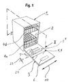
- the dishwasher 1 shown comprises a washing container 2, the front loading opening of which can be closed with a front door 3 which is hinged to a lower region of the dishwasher 1.
- the Rinsing containers 2 are one or more - two in the example shown - serving to accommodate items 30 washing baskets 4a, 4b mounted horizontally displaceably.
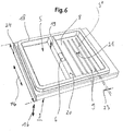
- an addition device 6 for active detergents such as detergents and / or rinse aid, for example on the upper edge of the door 3 or - as in Fig. 6 shown - in a relative to its longitudinal extent (which runs in the vertical direction when the door is closed) is arranged in the middle door area.
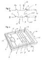
- a plurality of guide elements 9 spaced apart in the vertical direction 10 protrude from a flat surface 8 of the door inside 5. These extend horizontally or in the width direction 14 of the door 3 or the dishwasher 1. Viewed overall, they form a guide structure 9 *. If a vertical direction is spoken of here, this information relates to the operating state in which the door 3 is closed. The same applies to the depth direction mentioned below. For the sake of simplicity, these directions are retained in the drawings even when the door is open - horizontally aligned.
- the guide elements 9 can be separate components which are attached to the inside of the door 3, for example glued on. This can be useful if the inside of the door as a whole forms a flat surface 8 and is formed, for example, by a glass plate or plastic plate. If the door has on the inside, for example, a metallic embossed molded part 32, which is often also referred to as an inner door, the guide elements 9 are preferably formed in one piece with the embossed molded part 32. They are produced, for example, by embossing from the side of the embossed molded part 32 facing the door front, for example when the inner door is formed in a deep-drawing process.
- the guide elements 9 are each preferably designed in the form of ribs.
- they each have a straight longitudinal course in the width direction of the door. They therefore extend transversely, in particular perpendicularly, to the vertical flow direction of the drying fluid 11 rising along the inside of the door and, due to their raised protrusion from the inside of the door, they each form a spoiler or a deflecting element that deflects the flow of drying fluid in a horizontal direction Imprints the interior of the washing compartment.
- they can optionally have different cross-sectional shapes or contours 15, provided that these are suitable for deflecting the drying fluid in the manner described above.
- Guide elements 9 with a circular contour 15a and a triangular contour 15b are shown by way of example.
- a door can be provided with guide elements 9 of the same or different contours. It is thus conceivable to choose a different contour depending on the height level at which a guide element 9 is arranged on the door 3.
- guide elements 9 influencing the flow path are their depth 17, with which they protrude in the depth direction 16 from the door inside 5 or the flat surface 8 transversely, in particular perpendicularly to the latter.
- Guide elements 9 are preferably provided, the depth 17 of which is from 1 mm to 10 mm.
- the deflecting or guiding effect of the guiding elements is too small below 1 mm, so that a noticeable improvement in the drying effect can hardly be achieved.
- the guide element increasingly acts like a barrier, so that the guide elements 9 arranged downstream are no longer exposed to the flow of drying fluid 11, or no longer sufficiently.
- the aim is an approximately even division of the drying fluid 11 flowing along the inside of the door 5 into several partial flows directed towards the wash ware 30 or a wash basket 4a, 4b carrying the wash ware (arrows 36 in Fig. 2 ).
- Guide elements 9, which ensure this requirement with sufficient flow deflection, have a depth in the range of 3 mm to 7 mm.
- the guide elements 9 do not necessarily have to have one and the same depth 17. Rather, guide elements 9 of different depths 17 can be present. It is conceivable, for example, that the depth 17 changes as a function of the respective height or vertical position of the guide elements 9.
- the guide elements With regard to a trough-shaped recess in the inside of the door 5 or a receiving projection 20 which extends, for example, in the width direction 14 and serves to receive a functional component, such as a feed device 6 ( Fig. 6 ) the guide elements have a comparatively small depth 17. This only makes about 2% to 20%, preferably 5% to 15% the depth 19 of the edge bead 18 or a receiving projection 20 protruding from the flat surface 8 and serving to receive a functional component, for example a feed device 6.
- the guide elements 9 have a width in the vertical direction 10 or vertical extension 23 that is adapted to their depth 17. The larger this is, the less steep - for a given depth - the flank 241 of the guide elements 9 against which the drying fluid 11 flows.
- the above-mentioned depth extensions 17 Realize the guide elements 9 with sufficient deflection for the dry fluid flow.
- Another parameter that has an effect on the dry fluid flow is the density with which the guide elements 9 are arranged on the flat surface 8.
- the vertical distance 21 is therefore selected so that it is greater than the vertical extension 23 of the guide elements 9, namely 1 cm to 10 cm, preferably 2 cm to 5 cm.
- 1% to 20%, preferably 2% to 10% of the flat surface 8 is covered with guide elements 9.
- a number of 2 to 8, in particular 3 to 6, guide elements are expediently selected, which are provided on the inside of the door.
- the guide elements 9 run in the width direction 14 of the door 3, whereby they preferably extend over a range of 50% to 90% of the door width 24 in order to ensure a sufficient deflecting effect.
- a single guide element 9 can extend over the mentioned width range or rows 25 of several guide elements 9 'are provided.
- a transverse spacing 42 may be provided between two rows 25 provided next to one another in the width direction 14 can be spaced apart from one another in the height direction or vertical direction 10 arranged guide elements 9 ', each extending in the width direction 14, a transverse spacing 42 may be provided.
- guide structures 9 * specifically adapted to the respective flow and construction conditions can be provided in a simple manner.
- the intensity of the dry fluid flow decreases noticeably because of the deflection by the guide elements. It can therefore be expedient to arrange the guide elements 9 only on a surface area of the inside 5 of the door which, when the door 3 is closed, is below the height level 22 defined by the underside of the uppermost washing rack 4b. In the case of two or three washing baskets 4 arranged one above the other, it is therefore expedient to arrange guide elements 9 only in the lower two thirds of the inside 5 of the door.
- the drying fluid 11 flows through an outflow element 26 arranged on the bottom 31 of the washing container 2 into the washing container 2 and is subjected to a forced flow which is achieved, for example, by a circulating device 27, such as a fan, which is expediently positioned in the base installation space 28 of the dishwasher 1 .
- the outflow element 26 is designed in such a way that the drying fluid flow leaving it is directed towards the inside 5 of the door 3 in such a way that at least a partial flow of the drying fluid 11 hits the door inside 5 in the area of the lowermost wash basket 4a.
- the outflow element 26 is preferably arranged at the rear end 29 of the bottom 31 of the washing compartment, which is remote from the door 3. This ensures that the majority of the drying fluid 11 flows up through the underside of the lowermost wash basket 4a (arrows 39) and dries items 30 in the wash basket 4a and in the wash basket 4b located above it.
- a liquid-absorbing element, in particular a zeolite drying element 40, which removes water from the drying fluid 11, is arranged downstream of the circulating device 27.
- the drying element 40, the circulation device 27, the outflow element 26, the outlet 33 and their connecting lines are components of an air circulation system 41.
- part of the drying fluid 11 flows towards a lower area of the door inside 5 and is deflected vertically upwards, the drying fluid 11 initially flowing through a free space 35 existing between the lower washing basket 4a and the door inside 5.
- the guide elements 9 present there on the inside of the door 5 or the flat surface 8 direct the drying fluid flowing through the free space 35 onto the items to be washed 30, which are arranged closest to the door (see arrows 36).
- the uppermost guide element 9a is positioned in the area of the maximum loading height 37 of the wash basket 4a, deflecting drying fluid 11 over the wash items 30 towards the underside of the upper wash basket 4b (see arrow 38). In the free space 35 'between the upper washing rack 4b and the inside 5 of the door 3, there are preferably no guide elements 9, since this can only improve the drying result slightly.
- one or more guide elements protruding from the tub base for air deflection or air diversion are expediently provided in the flat or smooth tub base of the inner door, which is enclosed by an edge bead all around.
- the guide elements are preferably pressed in or molded in from the outside inwards, ie in the direction of the side facing the treatment room, in particular embossed (by embossing processes), or molded in by hydraulic forming. They are also provided on the otherwise flat surface of the inner door and protrude from it.
- the raised guide elements can each be designed as a linear or narrow strip-shaped rib or web that runs in the width direction of the inner door.
- a plurality of guide elements, in particular between 3 and 6, are preferably arranged one above the other at a predeterminable vertical distance. This multitude of guide elements forms a guide structure in stack form.
- a guide structure can optionally also be designed as a logo, symbol, font, etc.
- the one or the plurality of protruding structures are used for targeted air guidance and air deflection to a desired area in the interior of the washing compartment.
- the additional, one or more protruding or protruding guide elements or Profile elements are provided on the otherwise smooth, ie flat inner door surface. This ensures better ventilation of the items to be washed in the wash baskets, e.g. in the upper crockery basket and / or in a cutlery drawer above.
- the guide elements are provided in addition to the construction components that are usually present, such as an installation protrusion in the area of an upper edge zone of the door for adding detergent / rinse aid.
- the air can preferably be guided / directed to a special zone of the respective wash basket, in particular a crockery basket, which is provided for items to be washed, in particular items to be washed, which place particular demands on the drying performance.
- a special zone of the respective wash basket in particular a crockery basket, which is provided for items to be washed, in particular items to be washed, which place particular demands on the drying performance.
- This can be, for example, an area of the washing basket that is specially intended for plastic or plastic dishes, which is more difficult to dry than ceramic or porcelain due to its lack of mass.
- the guide elements or, in generalized terms, the guide structures protrude preferably between 1 mm and 10 mm, in particular between 3 and 7 mm, from the flat or planar inner surface of the inner door facing the interior of the washing compartment. (More does not make sense, as the air flow path between the inner door wall and the front of the crockery baskets must not be too narrow to avoid the air circulation in the interior of the washing container being torn off.)
- the protrusion of the one or more guide structures over the flat inner surface of the inner door is flat in relation to any existing installation protrusion for adding detergent / rinse aid.
- the respective guide structure is also much flatter than a bead that often surrounds the door pan of the door in many door constructions. When the door is completely closed in the vertical position, the respective guide structure preferably has an extension between 2% and 20% of the depth of the edge bead protruding in the depth direction relative to its door pan.
- the one or more guide structures are preferably provided on the lower 2/3 of the door inner wall.
- the upper third of the door remains free of guide structures (when the door is positioned vertically, viewed in height direction).
- An air flow that rises from below from the area of the washing container close to the floor can then be sufficiently divided up in good time before it reaches the top wall of the washing container, in particular before reaching the upper basket, and diverted into the interior of the washing container with a flow component in the depth direction. In particular, this ensures improved ventilation of the upper basket from below.
- the one or more conductive structures are preferably distributed over 1% to 20%, in particular between 2% and 10% of the inner wall surface of the door.
- guide elements running transversely on the inner door side ie extending in the width direction of the inner door
- these are preferably arranged essentially parallel and at a vertical distance from one another (based on the vertical closed position of the door).
- the height or vertical distance of any two adjacent guide elements is in particular greater than the height extension of the respective guide element (height based on the vertical closed end position of the door).
- the height distance from one guide rib to the next guide rib is preferably between 1 cm and 10 cm, in particular between 2 cm and 5 cm elected.
- the height extension of the respective guide element is preferably selected between 1 mm and 20 mm, in particular between 3 mm and 12 mm
- the width extension of the respective guide element is selected between 50% and 90% of the total width of the door.
- guide elements are expedient in order to be able to effect a sufficient deflection and redistribution of the air flow from the inside of the door into the interior of the washing compartment. It can be particularly useful if the guide elements are distributed along the height of the lower basket (from its lower edge to its upper edge) in the flat surface of the inner door in order to force the front, upward air flow into the gap between the lower basket and the upper basket can.
Landscapes
- Washing And Drying Of Tableware (AREA)
- Drying Of Solid Materials (AREA)
Claims (20)
- Lave-vaisselle (1), en particulier lave-vaisselle domestique, avec une cuve de lavage (2), avec un ou plusieurs paniers de lavage (4a, 4b) disposés dans la cuve de lavage (2) et servant à la réception de vaisselle à laver (30), et avec une porte avant (3) permettant de fermer la cuve de lavage (2), caractérisé en ce que vue dans la position de fermeture de la porte avant (3) à partir d'une surface plate (8) qui forme la face interne (5) de la porte avant (3) dans son ensemble ou une partie de celle-ci, au moins une structure de guidage (9*) sous la forme d'une pluralité d'éléments de guidage (9) individuels écartés les uns des autres verticalement fait saillie en relief dans l'espace interne de la cuve de lavage (2) et est disposée de telle sorte que lors d'une opération de séchage du lave-vaisselle (1) un fluide de séchage (11) circulant le long de la face interne (5) de la porte (3) est guidé sur la vaisselle à laver (30) disposée sur les un ou plusieurs paniers de lavage (4a, 4b) disposés dans la cuve de lavage (2) resp. sur les un ou plusieurs paniers de lavage (4a, 4b) dans la cuve de lavage (2).
- Lave-vaisselle selon la revendication 1, caractérisé en ce que la distance verticale (21) entre chacun de deux éléments de guidage (9) adjacents est plus grande que l'étendue verticale (23) de l'élément de guidage (9) respectif.
- Lave-vaisselle selon la revendication 2, caractérisé en ce qu'entre chacun de deux éléments de guidage (9) adjacents une distance verticale (23) de 1 cm à 10 cm, en particulier de 2 cm à 5 cm, est choisie.
- Lave-vaisselle selon l'une des revendications précédentes, caractérisé en ce que les plusieurs éléments de guidage (9) s'étendent pour l'essentiel parallèlement les uns par rapport aux autres.
- Lave-vaisselle selon l'une des revendications précédentes, caractérisé en ce que l'élément de guidage (9) respectif est réalisé sous la forme d'une nervure de guidage s'étendant dans la direction de la largeur (14) de la porte avant (3), en particulier sous une forme linéaire.
- Lave-vaisselle selon l'une des revendications précédentes, caractérisé en ce que l'élément de guidage (9) respectif vu dans la position de fermeture de la porte avant (3) présente une étendue verticale (23) de 1 mm à 20 mm, en particulier de 3 mm à 12 mm.
- Lave-vaisselle selon l'une des revendications précédentes, caractérisé en ce que les une ou plusieurs structures de guidage (9*) vues dans la position de fermeture de la porte avant (3) présentent respectivement une étendue en profondeur (17) de 1 mm à 10 mm, de préférence de 3 mm à 7 mm, avec laquelle vues dans la position de fermeture de la porte avant (3) elles font saillie respectivement de la surface plane (8) de la face interne (5) de celle-ci dans l'espace interne de la cuve de lavage (2).
- Lave-vaisselle selon l'une des revendications précédentes, caractérisé en ce que la face interne de porte (5) présente une cavité en forme de bassin (12) qui est délimitée par un bourrelet de bord (18).
- Lave-vaisselle selon la revendication 8, caractérisé en ce que, vue dans la position de fermeture de la porte avant (3) l'étendue en profondeur (17) des une ou plusieurs structures de guidage (9*), en particulier des éléments de guidage (9), représente respectivement 2 % à 20 %, en particulier 5 % à 15 %, de l'étendue en profondeur (17) du bourrelet de bord (18) de la porte avant (3).
- Lave-vaisselle selon l'une des revendications précédentes, caractérisé en ce que, vue dans la position de fermeture de la porte avant (3), l'étendue en profondeur (17) des une ou plusieurs structures de guidage (9*), en particulier des éléments de guidage (9), représente respectivement 2 % à 20 %, en particulier 5 % à 15 %, d'une saillie de réception (20) faisant saillie de la surface plane (8) de la face interne (5) de la porte avant (3) et servant à la réception d'un composant fonctionnel.
- Lave-vaisselle selon l'une des revendications précédentes, caractérisé en ce que 1 % à 20 %, en particulier 2 % à 10 %, de la surface plane (8) de la face interne (5) de la porte avant (3) sont recouverts par l'au moins une structure de guidage (9*), en particulier par les éléments de guidage (9).
- Lave-vaisselle selon l'une des revendications précédentes, caractérisé en ce que les une ou plusieurs structures de guidage (9*), en particulier les éléments de guidage (9), s'étendent sur 50 % à 90 % de la largeur (24) de la porte avant (3).
- Lave-vaisselle selon l'une des revendications précédentes, caractérisé en ce que les une ou plusieurs structures de guidage (9*), en particulier les éléments de guidage (9), sont disposés uniquement dans les deux tiers inférieurs de la face interne (5) de la porte avant (3).
- Lave-vaisselle selon l'une des revendications précédentes, caractérisé en ce que les une ou plusieurs structures de guidage (9*), en particulier les éléments de guidage (9), sont disposés uniquement au niveau d'une zone de surface de la face interne (5) de la porte avant (3) qui se trouve en dessous du niveau de hauteur (22) défini par la face inférieure d'un panier de lavage (4a) supérieur ou le plus élevé.
- Lave-vaisselle selon l'une des revendications précédentes, caractérisé en ce qu'entre 2 et 8, en particulier entre 3 et 6, éléments de guidage (9) sont prévus sur la face interne (5) de la porte avant (3).
- Lave-vaisselle selon l'une des revendications précédentes, caractérisé en ce que les une ou plusieurs structures de guidage (9*), en particulier les éléments de guidage (9), sont réalisées d'un seul tenant avec une pièce moulée par moulage (32) formant la face interne de porte (5).
- Lave-vaisselle selon l'une des revendications précédentes, caractérisé par un système de séchage par circulation (41) servant au séchage du fluide de séchage (11), qui comprend en particulier un élément de séchage par absorption, de préférence un élément de séchage par zéolithe (40).
- Lave-vaisselle (2) selon l'une des revendications précédentes, caractérisé par un dispositif de circulation (27) permettant une circulation forcée du fluide de séchage (11).
- Lave-vaisselle selon l'une des revendications précédentes, caractérisé par un élément de diffusion (26) présent dans la cuve de lavage (2), lequel élément de diffusion est conçu de sorte que le fluide de séchage (11) circulant dans la cuve de lavage est dirigé contre la face interne (5) de la porte avant (3) au moins en partie avec un composant de direction s'étendant pour l'essentiel horizontalement.
- Lave-vaisselle selon la revendication 19, caractérisé en ce que l'élément de diffusion (26) est disposé dans le fond (31) de la cuve de lavage (2).
Priority Applications (1)
| Application Number | Priority Date | Filing Date | Title |
|---|---|---|---|
| PL13736797T PL2869747T3 (pl) | 2012-07-04 | 2013-06-21 | Zmywarka do naczyń, zwłaszcza zmywarka do naczyń gospodarstwa domowego, z co najmniej jedną strukturą prowadzącą na wewnętrznej stronie drzwi do zmiany kierunku przepływającego tam wzdłużnie płynu suszącego |
Applications Claiming Priority (2)
| Application Number | Priority Date | Filing Date | Title |
|---|---|---|---|
| DE102012211627.3A DE102012211627B4 (de) | 2012-07-04 | 2012-07-04 | Geschirrspülmaschine, insbesondere Haushaltsgeschirrspülmaschine, mit wenigstens einer Leitstruktur an ihrer Türinnenseite zum Umlenken von dort entlang strömenden Trocknungsfluid |
| PCT/EP2013/062988 WO2014005857A2 (fr) | 2012-07-04 | 2013-06-21 | Lave-vaisselle, en particulier lave-vaisselle à usage domestique, comprenant au moins une structure de guidage permettant de dévier un fluide de séchage s'écoulant le long de la face intérieure de la porte du lave-vaisselle |
Publications (2)
| Publication Number | Publication Date |
|---|---|
| EP2869747A2 EP2869747A2 (fr) | 2015-05-13 |
| EP2869747B1 true EP2869747B1 (fr) | 2021-04-28 |
Family
ID=48790356
Family Applications (1)
| Application Number | Title | Priority Date | Filing Date |
|---|---|---|---|
| EP13736797.5A Active EP2869747B1 (fr) | 2012-07-04 | 2013-06-21 | Lave-vaisselle, en particulier lave-vaisselle à usage domestique, comprenant au moins une structure de guidage permettant de dévier un fluide de séchage s'écoulant le long de la face intérieure de la porte du lave-vaisselle |
Country Status (6)
| Country | Link |
|---|---|
| US (2) | US9901241B2 (fr) |
| EP (1) | EP2869747B1 (fr) |
| CN (1) | CN104582556B (fr) |
| DE (1) | DE102012211627B4 (fr) |
| PL (1) | PL2869747T3 (fr) |
| WO (1) | WO2014005857A2 (fr) |
Families Citing this family (4)
| Publication number | Priority date | Publication date | Assignee | Title |
|---|---|---|---|---|
| DE102012211627B4 (de) * | 2012-07-04 | 2024-11-07 | BSH Hausgeräte GmbH | Geschirrspülmaschine, insbesondere Haushaltsgeschirrspülmaschine, mit wenigstens einer Leitstruktur an ihrer Türinnenseite zum Umlenken von dort entlang strömenden Trocknungsfluid |
| CN111936026B (zh) * | 2018-04-10 | 2024-08-30 | Bsh家用电器有限公司 | 具有至少一个用于由流体穿流的管件的加热器的家用电器 |
| US10506912B2 (en) * | 2018-05-16 | 2019-12-17 | Haier Us Appliance Solutions, Inc. | Dishwasher appliance with vent duct mixing |
| CN109998438B (zh) * | 2019-04-15 | 2020-10-02 | 佛山市顺德区美的洗涤电器制造有限公司 | 洗碗机、洗碗机的使用指导装置及方法 |
Family Cites Families (13)
| Publication number | Priority date | Publication date | Assignee | Title |
|---|---|---|---|---|
| DE2610379C3 (de) * | 1976-03-12 | 1984-02-09 | Bosch-Siemens Hausgeräte GmbH, 7000 Stuttgart | Geschirrspülmaschine |
| DE19805066A1 (de) * | 1998-02-10 | 1999-08-12 | Winterhalter Gastronom Gmbh | Geschirrspülmaschine |
| DE10257650A1 (de) * | 2002-12-10 | 2004-06-24 | BSH Bosch und Siemens Hausgeräte GmbH | Heizvorrichtung zum Trocknen von Spülgut in einer Geschirrspülmaschine |
| DE102005023428A1 (de) | 2005-05-20 | 2006-11-23 | Premark Feg L.L.C. (N.D.Ges.D. Staates Delaware), Wilmington | Gewerbliche Geschirrspülmaschine |
| SI1825800T1 (sl) * | 2006-02-22 | 2013-08-30 | V-Zug Ag | Pomivalni stroj s sredstvom za odvod vlage iz kadi |
| DE102007007133A1 (de) * | 2007-02-13 | 2008-08-14 | Meiko Maschinenbau Gmbh & Co. Kg | Frontlader-Geschirrspülmaschine mit Wärmerückgewinnung |
| EP1961361B1 (fr) * | 2007-02-20 | 2011-02-16 | Electrolux Home Products Corporation N.V. | Système de séchage pour lave-vaisselle |
| DE102007008826A1 (de) | 2007-02-22 | 2008-08-28 | Premark Feg L.L.C., Wilmington | Gewerbliche Geschirrspülmaschine und Verfahren zu ihrem Betrieb |
| US20090151758A1 (en) * | 2007-12-12 | 2009-06-18 | Electrolux Home Products, Inc. | Lower rack for a dishwasher and associated apparatuses |
| RU2011104426A (ru) * | 2008-07-28 | 2012-09-10 | Бсх Бош Унд Сименс Хаусгерете Гмбх (De) | Посудомоечная машина с сорбционным сушильным устройством |
| DE102008040789A1 (de) * | 2008-07-28 | 2010-02-04 | BSH Bosch und Siemens Hausgeräte GmbH | Geschirrspülmaschine mit Sorptionstrocknungsvorrichtung |
| DE102008043548A1 (de) * | 2008-11-07 | 2010-05-12 | BSH Bosch und Siemens Hausgeräte GmbH | Verfahren zum Betreiben einer Geschirrspülmaschine |
| DE102012211627B4 (de) * | 2012-07-04 | 2024-11-07 | BSH Hausgeräte GmbH | Geschirrspülmaschine, insbesondere Haushaltsgeschirrspülmaschine, mit wenigstens einer Leitstruktur an ihrer Türinnenseite zum Umlenken von dort entlang strömenden Trocknungsfluid |
-
2012
- 2012-07-04 DE DE102012211627.3A patent/DE102012211627B4/de active Active
-
2013
- 2013-06-21 WO PCT/EP2013/062988 patent/WO2014005857A2/fr not_active Ceased
- 2013-06-21 US US14/407,082 patent/US9901241B2/en active Active
- 2013-06-21 CN CN201380035174.5A patent/CN104582556B/zh active Active
- 2013-06-21 EP EP13736797.5A patent/EP2869747B1/fr active Active
- 2013-06-21 PL PL13736797T patent/PL2869747T3/pl unknown
-
2017
- 2017-11-22 US US15/820,472 patent/US10945583B2/en active Active
Non-Patent Citations (1)
| Title |
|---|
| None * |
Also Published As
| Publication number | Publication date |
|---|---|
| DE102012211627B4 (de) | 2024-11-07 |
| EP2869747A2 (fr) | 2015-05-13 |
| DE102012211627A1 (de) | 2014-01-09 |
| US20150157186A1 (en) | 2015-06-11 |
| US9901241B2 (en) | 2018-02-27 |
| CN104582556B (zh) | 2017-10-27 |
| PL2869747T3 (pl) | 2021-11-02 |
| CN104582556A (zh) | 2015-04-29 |
| US20180103826A1 (en) | 2018-04-19 |
| US10945583B2 (en) | 2021-03-16 |
| WO2014005857A2 (fr) | 2014-01-09 |
| WO2014005857A3 (fr) | 2014-06-26 |
Similar Documents
| Publication | Publication Date | Title |
|---|---|---|
| EP2635172B1 (fr) | Lave-vaisselle équipé d'au moins un bras de pulvérisation rotatif | |
| EP2869747B1 (fr) | Lave-vaisselle, en particulier lave-vaisselle à usage domestique, comprenant au moins une structure de guidage permettant de dévier un fluide de séchage s'écoulant le long de la face intérieure de la porte du lave-vaisselle | |
| EP4248140A1 (fr) | Appareil de cuisson comprenant un système à air chaud et séparateur de chambre de cuisson de forme spécifique dans la zone d'une paroi avant du système à air chaud | |
| EP3747338B1 (fr) | Panier pour laves-vaisselles | |
| WO2002053009A1 (fr) | Recipient de rincage pour lave-vaisselle | |
| EP2271248B1 (fr) | Panier à vaisselle et lave-vaisselle | |
| EP1287780B1 (fr) | Panier pour lave-vaisselle | |
| EP1345526B2 (fr) | Dispositif destine a ameliorer la capacite de sechage d'un lave-vaisselle | |
| DE102010062780B4 (de) | Geschirrspülmaschine, insbesondere Haushaltsgeschirrspülmaschine | |
| EP1833351B1 (fr) | Lave-vaisselle comprenant un dispositif de sechage | |
| EP3337626A1 (fr) | Support d'alvéoles pour bouteilles et machine de nettoyage comportant une pluralité de supports d'alvéoles pour bouteilles | |
| EP1337178B1 (fr) | Garniture pour panier d'un lave-vaisselle | |
| AT522471B1 (de) | Spülkorb für Spülmaschinen | |
| EP3335616A1 (fr) | Lave-vaisselle à usage ménager pourvu de système de pompe à chaleur | |
| EP3431650B1 (fr) | Module de plancher pour une pompe à chaleur | |
| EP3863491B1 (fr) | Lave-vaisselle ménager | |
| DE102007030074A1 (de) | Innenbehälter für eine Geschirrspülmaschine | |
| EP2486839B1 (fr) | Lave-vaisselle doté d'un joint de porte | |
| DE102013210015B4 (de) | Führungsschiene für eine Geschirrspülmaschine | |
| DE102011010150B4 (de) | Einhängegestell für ein Gargerät | |
| EP2217126A1 (fr) | Appareil ménager | |
| DE102009000926A1 (de) | Geschirrspülmaschine mit mindestens einem Spülkorb aus einer Blechmatte | |
| EP2494907B1 (fr) | Lave-vaisselle doté d'un panier supérieur réglable | |
| EP2312990B1 (fr) | Lave-vaisselle | |
| DE20023824U1 (de) | Einsatz für einen Geschirrkorb einer Geschirrspülmaschine |
Legal Events
| Date | Code | Title | Description |
|---|---|---|---|
| PUAI | Public reference made under article 153(3) epc to a published international application that has entered the european phase |
Free format text: ORIGINAL CODE: 0009012 |
|
| 17P | Request for examination filed |
Effective date: 20150204 |
|
| AK | Designated contracting states |
Kind code of ref document: A2 Designated state(s): AL AT BE BG CH CY CZ DE DK EE ES FI FR GB GR HR HU IE IS IT LI LT LU LV MC MK MT NL NO PL PT RO RS SE SI SK SM TR |
|
| AX | Request for extension of the european patent |
Extension state: BA ME |
|
| DAX | Request for extension of the european patent (deleted) | ||
| GRAP | Despatch of communication of intention to grant a patent |
Free format text: ORIGINAL CODE: EPIDOSNIGR1 |
|
| STAA | Information on the status of an ep patent application or granted ep patent |
Free format text: STATUS: GRANT OF PATENT IS INTENDED |
|
| INTG | Intention to grant announced |
Effective date: 20201216 |
|
| RIN1 | Information on inventor provided before grant (corrected) |
Inventor name: ROSENBAUER, MICHAEL, GEORG Inventor name: NANNT, HANS-PETER Inventor name: JERG, HELMUT |
|
| GRAS | Grant fee paid |
Free format text: ORIGINAL CODE: EPIDOSNIGR3 |
|
| GRAA | (expected) grant |
Free format text: ORIGINAL CODE: 0009210 |
|
| STAA | Information on the status of an ep patent application or granted ep patent |
Free format text: STATUS: THE PATENT HAS BEEN GRANTED |
|
| AK | Designated contracting states |
Kind code of ref document: B1 Designated state(s): AL AT BE BG CH CY CZ DE DK EE ES FI FR GB GR HR HU IE IS IT LI LT LU LV MC MK MT NL NO PL PT RO RS SE SI SK SM TR |
|
| REG | Reference to a national code |
Ref country code: GB Ref legal event code: FG4D Free format text: NOT ENGLISH |
|
| REG | Reference to a national code |
Ref country code: CH Ref legal event code: EP |
|
| REG | Reference to a national code |
Ref country code: AT Ref legal event code: REF Ref document number: 1386165 Country of ref document: AT Kind code of ref document: T Effective date: 20210515 |
|
| REG | Reference to a national code |
Ref country code: DE Ref legal event code: R096 Ref document number: 502013015683 Country of ref document: DE |
|
| REG | Reference to a national code |
Ref country code: IE Ref legal event code: FG4D Free format text: LANGUAGE OF EP DOCUMENT: GERMAN |
|
| REG | Reference to a national code |
Ref country code: LT Ref legal event code: MG9D |
|
| PG25 | Lapsed in a contracting state [announced via postgrant information from national office to epo] |
Ref country code: NL Free format text: LAPSE BECAUSE OF FAILURE TO SUBMIT A TRANSLATION OF THE DESCRIPTION OR TO PAY THE FEE WITHIN THE PRESCRIBED TIME-LIMIT Effective date: 20210428 Ref country code: LT Free format text: LAPSE BECAUSE OF FAILURE TO SUBMIT A TRANSLATION OF THE DESCRIPTION OR TO PAY THE FEE WITHIN THE PRESCRIBED TIME-LIMIT Effective date: 20210428 Ref country code: FI Free format text: LAPSE BECAUSE OF FAILURE TO SUBMIT A TRANSLATION OF THE DESCRIPTION OR TO PAY THE FEE WITHIN THE PRESCRIBED TIME-LIMIT Effective date: 20210428 Ref country code: HR Free format text: LAPSE BECAUSE OF FAILURE TO SUBMIT A TRANSLATION OF THE DESCRIPTION OR TO PAY THE FEE WITHIN THE PRESCRIBED TIME-LIMIT Effective date: 20210428 Ref country code: BG Free format text: LAPSE BECAUSE OF FAILURE TO SUBMIT A TRANSLATION OF THE DESCRIPTION OR TO PAY THE FEE WITHIN THE PRESCRIBED TIME-LIMIT Effective date: 20210728 |
|
| PG25 | Lapsed in a contracting state [announced via postgrant information from national office to epo] |
Ref country code: RS Free format text: LAPSE BECAUSE OF FAILURE TO SUBMIT A TRANSLATION OF THE DESCRIPTION OR TO PAY THE FEE WITHIN THE PRESCRIBED TIME-LIMIT Effective date: 20210428 Ref country code: SE Free format text: LAPSE BECAUSE OF FAILURE TO SUBMIT A TRANSLATION OF THE DESCRIPTION OR TO PAY THE FEE WITHIN THE PRESCRIBED TIME-LIMIT Effective date: 20210428 Ref country code: LV Free format text: LAPSE BECAUSE OF FAILURE TO SUBMIT A TRANSLATION OF THE DESCRIPTION OR TO PAY THE FEE WITHIN THE PRESCRIBED TIME-LIMIT Effective date: 20210428 Ref country code: IS Free format text: LAPSE BECAUSE OF FAILURE TO SUBMIT A TRANSLATION OF THE DESCRIPTION OR TO PAY THE FEE WITHIN THE PRESCRIBED TIME-LIMIT Effective date: 20210828 Ref country code: GR Free format text: LAPSE BECAUSE OF FAILURE TO SUBMIT A TRANSLATION OF THE DESCRIPTION OR TO PAY THE FEE WITHIN THE PRESCRIBED TIME-LIMIT Effective date: 20210729 Ref country code: PT Free format text: LAPSE BECAUSE OF FAILURE TO SUBMIT A TRANSLATION OF THE DESCRIPTION OR TO PAY THE FEE WITHIN THE PRESCRIBED TIME-LIMIT Effective date: 20210830 Ref country code: NO Free format text: LAPSE BECAUSE OF FAILURE TO SUBMIT A TRANSLATION OF THE DESCRIPTION OR TO PAY THE FEE WITHIN THE PRESCRIBED TIME-LIMIT Effective date: 20210728 Ref country code: ES Free format text: LAPSE BECAUSE OF FAILURE TO SUBMIT A TRANSLATION OF THE DESCRIPTION OR TO PAY THE FEE WITHIN THE PRESCRIBED TIME-LIMIT Effective date: 20210428 |
|
| REG | Reference to a national code |
Ref country code: NL Ref legal event code: MP Effective date: 20210428 |
|
| PG25 | Lapsed in a contracting state [announced via postgrant information from national office to epo] |
Ref country code: SK Free format text: LAPSE BECAUSE OF FAILURE TO SUBMIT A TRANSLATION OF THE DESCRIPTION OR TO PAY THE FEE WITHIN THE PRESCRIBED TIME-LIMIT Effective date: 20210428 Ref country code: SM Free format text: LAPSE BECAUSE OF FAILURE TO SUBMIT A TRANSLATION OF THE DESCRIPTION OR TO PAY THE FEE WITHIN THE PRESCRIBED TIME-LIMIT Effective date: 20210428 Ref country code: CZ Free format text: LAPSE BECAUSE OF FAILURE TO SUBMIT A TRANSLATION OF THE DESCRIPTION OR TO PAY THE FEE WITHIN THE PRESCRIBED TIME-LIMIT Effective date: 20210428 Ref country code: EE Free format text: LAPSE BECAUSE OF FAILURE TO SUBMIT A TRANSLATION OF THE DESCRIPTION OR TO PAY THE FEE WITHIN THE PRESCRIBED TIME-LIMIT Effective date: 20210428 Ref country code: DK Free format text: LAPSE BECAUSE OF FAILURE TO SUBMIT A TRANSLATION OF THE DESCRIPTION OR TO PAY THE FEE WITHIN THE PRESCRIBED TIME-LIMIT Effective date: 20210428 Ref country code: MC Free format text: LAPSE BECAUSE OF FAILURE TO SUBMIT A TRANSLATION OF THE DESCRIPTION OR TO PAY THE FEE WITHIN THE PRESCRIBED TIME-LIMIT Effective date: 20210428 Ref country code: RO Free format text: LAPSE BECAUSE OF FAILURE TO SUBMIT A TRANSLATION OF THE DESCRIPTION OR TO PAY THE FEE WITHIN THE PRESCRIBED TIME-LIMIT Effective date: 20210428 |
|
| REG | Reference to a national code |
Ref country code: DE Ref legal event code: R097 Ref document number: 502013015683 Country of ref document: DE Ref country code: CH Ref legal event code: PL |
|
| PLBE | No opposition filed within time limit |
Free format text: ORIGINAL CODE: 0009261 |
|
| STAA | Information on the status of an ep patent application or granted ep patent |
Free format text: STATUS: NO OPPOSITION FILED WITHIN TIME LIMIT |
|
| REG | Reference to a national code |
Ref country code: BE Ref legal event code: MM Effective date: 20210630 |
|
| GBPC | Gb: european patent ceased through non-payment of renewal fee |
Effective date: 20210728 |
|
| PG25 | Lapsed in a contracting state [announced via postgrant information from national office to epo] |
Ref country code: LU Free format text: LAPSE BECAUSE OF NON-PAYMENT OF DUE FEES Effective date: 20210621 |
|
| 26N | No opposition filed |
Effective date: 20220131 |
|
| PG25 | Lapsed in a contracting state [announced via postgrant information from national office to epo] |
Ref country code: LI Free format text: LAPSE BECAUSE OF NON-PAYMENT OF DUE FEES Effective date: 20210630 Ref country code: IE Free format text: LAPSE BECAUSE OF NON-PAYMENT OF DUE FEES Effective date: 20210621 Ref country code: GB Free format text: LAPSE BECAUSE OF NON-PAYMENT OF DUE FEES Effective date: 20210728 Ref country code: CH Free format text: LAPSE BECAUSE OF NON-PAYMENT OF DUE FEES Effective date: 20210630 |
|
| PG25 | Lapsed in a contracting state [announced via postgrant information from national office to epo] |
Ref country code: IS Free format text: LAPSE BECAUSE OF FAILURE TO SUBMIT A TRANSLATION OF THE DESCRIPTION OR TO PAY THE FEE WITHIN THE PRESCRIBED TIME-LIMIT Effective date: 20210828 Ref country code: FR Free format text: LAPSE BECAUSE OF NON-PAYMENT OF DUE FEES Effective date: 20210628 Ref country code: AL Free format text: LAPSE BECAUSE OF FAILURE TO SUBMIT A TRANSLATION OF THE DESCRIPTION OR TO PAY THE FEE WITHIN THE PRESCRIBED TIME-LIMIT Effective date: 20210428 |
|
| PG25 | Lapsed in a contracting state [announced via postgrant information from national office to epo] |
Ref country code: IT Free format text: LAPSE BECAUSE OF FAILURE TO SUBMIT A TRANSLATION OF THE DESCRIPTION OR TO PAY THE FEE WITHIN THE PRESCRIBED TIME-LIMIT Effective date: 20210428 Ref country code: BE Free format text: LAPSE BECAUSE OF NON-PAYMENT OF DUE FEES Effective date: 20210630 |
|
| REG | Reference to a national code |
Ref country code: AT Ref legal event code: MM01 Ref document number: 1386165 Country of ref document: AT Kind code of ref document: T Effective date: 20210621 |
|
| PG25 | Lapsed in a contracting state [announced via postgrant information from national office to epo] |
Ref country code: AT Free format text: LAPSE BECAUSE OF NON-PAYMENT OF DUE FEES Effective date: 20210621 |
|
| PG25 | Lapsed in a contracting state [announced via postgrant information from national office to epo] |
Ref country code: HU Free format text: LAPSE BECAUSE OF FAILURE TO SUBMIT A TRANSLATION OF THE DESCRIPTION OR TO PAY THE FEE WITHIN THE PRESCRIBED TIME-LIMIT; INVALID AB INITIO Effective date: 20130621 |
|
| PG25 | Lapsed in a contracting state [announced via postgrant information from national office to epo] |
Ref country code: CY Free format text: LAPSE BECAUSE OF FAILURE TO SUBMIT A TRANSLATION OF THE DESCRIPTION OR TO PAY THE FEE WITHIN THE PRESCRIBED TIME-LIMIT Effective date: 20210428 |
|
| PG25 | Lapsed in a contracting state [announced via postgrant information from national office to epo] |
Ref country code: MK Free format text: LAPSE BECAUSE OF FAILURE TO SUBMIT A TRANSLATION OF THE DESCRIPTION OR TO PAY THE FEE WITHIN THE PRESCRIBED TIME-LIMIT Effective date: 20210428 |
|
| PG25 | Lapsed in a contracting state [announced via postgrant information from national office to epo] |
Ref country code: MT Free format text: LAPSE BECAUSE OF FAILURE TO SUBMIT A TRANSLATION OF THE DESCRIPTION OR TO PAY THE FEE WITHIN THE PRESCRIBED TIME-LIMIT Effective date: 20210428 |
|
| PGFP | Annual fee paid to national office [announced via postgrant information from national office to epo] |
Ref country code: PL Payment date: 20250610 Year of fee payment: 13 Ref country code: DE Payment date: 20250630 Year of fee payment: 13 |
|
| PGFP | Annual fee paid to national office [announced via postgrant information from national office to epo] |
Ref country code: TR Payment date: 20250618 Year of fee payment: 13 |