EP2870268B1 - Verfahren und vorrichtung zur vermeidung von durch zinkstaub verursachten oberflächenfehlern in einer kontinuierlichen bandverzinkung - Google Patents
Verfahren und vorrichtung zur vermeidung von durch zinkstaub verursachten oberflächenfehlern in einer kontinuierlichen bandverzinkung Download PDFInfo
- Publication number
- EP2870268B1 EP2870268B1 EP13735251.4A EP13735251A EP2870268B1 EP 2870268 B1 EP2870268 B1 EP 2870268B1 EP 13735251 A EP13735251 A EP 13735251A EP 2870268 B1 EP2870268 B1 EP 2870268B1
- Authority
- EP
- European Patent Office
- Prior art keywords
- openings
- furnace gas
- injection
- zinc
- extraction
- Prior art date
- Legal status (The legal status is an assumption and is not a legal conclusion. Google has not performed a legal analysis and makes no representation as to the accuracy of the status listed.)
- Not-in-force
Links
Images


Classifications
-
- C—CHEMISTRY; METALLURGY
- C21—METALLURGY OF IRON
- C21D—MODIFYING THE PHYSICAL STRUCTURE OF FERROUS METALS; GENERAL DEVICES FOR HEAT TREATMENT OF FERROUS OR NON-FERROUS METALS OR ALLOYS; MAKING METAL MALLEABLE, e.g. BY DECARBURISATION OR TEMPERING
- C21D1/00—General methods or devices for heat treatment, e.g. annealing, hardening, quenching or tempering
- C21D1/26—Methods of annealing
-
- C—CHEMISTRY; METALLURGY
- C21—METALLURGY OF IRON
- C21D—MODIFYING THE PHYSICAL STRUCTURE OF FERROUS METALS; GENERAL DEVICES FOR HEAT TREATMENT OF FERROUS OR NON-FERROUS METALS OR ALLOYS; MAKING METAL MALLEABLE, e.g. BY DECARBURISATION OR TEMPERING
- C21D9/00—Heat treatment, e.g. annealing, hardening, quenching or tempering, adapted for particular articles; Furnaces therefor
- C21D9/52—Heat treatment, e.g. annealing, hardening, quenching or tempering, adapted for particular articles; Furnaces therefor for wires; for strips ; for rods of unlimited length
-
- C—CHEMISTRY; METALLURGY
- C21—METALLURGY OF IRON
- C21D—MODIFYING THE PHYSICAL STRUCTURE OF FERROUS METALS; GENERAL DEVICES FOR HEAT TREATMENT OF FERROUS OR NON-FERROUS METALS OR ALLOYS; MAKING METAL MALLEABLE, e.g. BY DECARBURISATION OR TEMPERING
- C21D9/00—Heat treatment, e.g. annealing, hardening, quenching or tempering, adapted for particular articles; Furnaces therefor
- C21D9/52—Heat treatment, e.g. annealing, hardening, quenching or tempering, adapted for particular articles; Furnaces therefor for wires; for strips ; for rods of unlimited length
- C21D9/54—Furnaces for treating strips or wire
- C21D9/56—Continuous furnaces for strip or wire
- C21D9/561—Continuous furnaces for strip or wire with a controlled atmosphere or vacuum
-
- C—CHEMISTRY; METALLURGY
- C23—COATING METALLIC MATERIAL; COATING MATERIAL WITH METALLIC MATERIAL; CHEMICAL SURFACE TREATMENT; DIFFUSION TREATMENT OF METALLIC MATERIAL; COATING BY VACUUM EVAPORATION, BY SPUTTERING, BY ION IMPLANTATION OR BY CHEMICAL VAPOUR DEPOSITION, IN GENERAL; INHIBITING CORROSION OF METALLIC MATERIAL OR INCRUSTATION IN GENERAL
- C23C—COATING METALLIC MATERIAL; COATING MATERIAL WITH METALLIC MATERIAL; SURFACE TREATMENT OF METALLIC MATERIAL BY DIFFUSION INTO THE SURFACE, BY CHEMICAL CONVERSION OR SUBSTITUTION; COATING BY VACUUM EVAPORATION, BY SPUTTERING, BY ION IMPLANTATION OR BY CHEMICAL VAPOUR DEPOSITION, IN GENERAL
- C23C2/00—Hot-dipping or immersion processes for applying the coating material in the molten state without affecting the shape; Apparatus therefor
- C23C2/003—Apparatus
- C23C2/0034—Details related to elements immersed in bath
- C23C2/00342—Moving elements, e.g. pumps or mixers
- C23C2/00344—Means for moving substrates, e.g. immersed rollers or immersed bearings
-
- C—CHEMISTRY; METALLURGY
- C23—COATING METALLIC MATERIAL; COATING MATERIAL WITH METALLIC MATERIAL; CHEMICAL SURFACE TREATMENT; DIFFUSION TREATMENT OF METALLIC MATERIAL; COATING BY VACUUM EVAPORATION, BY SPUTTERING, BY ION IMPLANTATION OR BY CHEMICAL VAPOUR DEPOSITION, IN GENERAL; INHIBITING CORROSION OF METALLIC MATERIAL OR INCRUSTATION IN GENERAL
- C23C—COATING METALLIC MATERIAL; COATING MATERIAL WITH METALLIC MATERIAL; SURFACE TREATMENT OF METALLIC MATERIAL BY DIFFUSION INTO THE SURFACE, BY CHEMICAL CONVERSION OR SUBSTITUTION; COATING BY VACUUM EVAPORATION, BY SPUTTERING, BY ION IMPLANTATION OR BY CHEMICAL VAPOUR DEPOSITION, IN GENERAL
- C23C2/00—Hot-dipping or immersion processes for applying the coating material in the molten state without affecting the shape; Apparatus therefor
- C23C2/003—Apparatus
- C23C2/0038—Apparatus characterised by the pre-treatment chambers located immediately upstream of the bath or occurring locally before the dipping process
- C23C2/004—Snouts
-
- C—CHEMISTRY; METALLURGY
- C23—COATING METALLIC MATERIAL; COATING MATERIAL WITH METALLIC MATERIAL; CHEMICAL SURFACE TREATMENT; DIFFUSION TREATMENT OF METALLIC MATERIAL; COATING BY VACUUM EVAPORATION, BY SPUTTERING, BY ION IMPLANTATION OR BY CHEMICAL VAPOUR DEPOSITION, IN GENERAL; INHIBITING CORROSION OF METALLIC MATERIAL OR INCRUSTATION IN GENERAL
- C23C—COATING METALLIC MATERIAL; COATING MATERIAL WITH METALLIC MATERIAL; SURFACE TREATMENT OF METALLIC MATERIAL BY DIFFUSION INTO THE SURFACE, BY CHEMICAL CONVERSION OR SUBSTITUTION; COATING BY VACUUM EVAPORATION, BY SPUTTERING, BY ION IMPLANTATION OR BY CHEMICAL VAPOUR DEPOSITION, IN GENERAL
- C23C2/00—Hot-dipping or immersion processes for applying the coating material in the molten state without affecting the shape; Apparatus therefor
- C23C2/02—Pretreatment of the material to be coated, e.g. for coating on selected surface areas
- C23C2/022—Pretreatment of the material to be coated, e.g. for coating on selected surface areas by heating
-
- C—CHEMISTRY; METALLURGY
- C23—COATING METALLIC MATERIAL; COATING MATERIAL WITH METALLIC MATERIAL; CHEMICAL SURFACE TREATMENT; DIFFUSION TREATMENT OF METALLIC MATERIAL; COATING BY VACUUM EVAPORATION, BY SPUTTERING, BY ION IMPLANTATION OR BY CHEMICAL VAPOUR DEPOSITION, IN GENERAL; INHIBITING CORROSION OF METALLIC MATERIAL OR INCRUSTATION IN GENERAL
- C23C—COATING METALLIC MATERIAL; COATING MATERIAL WITH METALLIC MATERIAL; SURFACE TREATMENT OF METALLIC MATERIAL BY DIFFUSION INTO THE SURFACE, BY CHEMICAL CONVERSION OR SUBSTITUTION; COATING BY VACUUM EVAPORATION, BY SPUTTERING, BY ION IMPLANTATION OR BY CHEMICAL VAPOUR DEPOSITION, IN GENERAL
- C23C2/00—Hot-dipping or immersion processes for applying the coating material in the molten state without affecting the shape; Apparatus therefor
- C23C2/04—Hot-dipping or immersion processes for applying the coating material in the molten state without affecting the shape; Apparatus therefor characterised by the coating material
- C23C2/06—Zinc or cadmium or alloys based thereon
-
- C—CHEMISTRY; METALLURGY
- C23—COATING METALLIC MATERIAL; COATING MATERIAL WITH METALLIC MATERIAL; CHEMICAL SURFACE TREATMENT; DIFFUSION TREATMENT OF METALLIC MATERIAL; COATING BY VACUUM EVAPORATION, BY SPUTTERING, BY ION IMPLANTATION OR BY CHEMICAL VAPOUR DEPOSITION, IN GENERAL; INHIBITING CORROSION OF METALLIC MATERIAL OR INCRUSTATION IN GENERAL
- C23C—COATING METALLIC MATERIAL; COATING MATERIAL WITH METALLIC MATERIAL; SURFACE TREATMENT OF METALLIC MATERIAL BY DIFFUSION INTO THE SURFACE, BY CHEMICAL CONVERSION OR SUBSTITUTION; COATING BY VACUUM EVAPORATION, BY SPUTTERING, BY ION IMPLANTATION OR BY CHEMICAL VAPOUR DEPOSITION, IN GENERAL
- C23C2/00—Hot-dipping or immersion processes for applying the coating material in the molten state without affecting the shape; Apparatus therefor
- C23C2/34—Hot-dipping or immersion processes for applying the coating material in the molten state without affecting the shape; Apparatus therefor characterised by the shape of the material to be treated
- C23C2/36—Elongated material
- C23C2/40—Plates; Strips
-
- B—PERFORMING OPERATIONS; TRANSPORTING
- B05—SPRAYING OR ATOMISING IN GENERAL; APPLYING FLUENT MATERIALS TO SURFACES, IN GENERAL
- B05D—PROCESSES FOR APPLYING FLUENT MATERIALS TO SURFACES, IN GENERAL
- B05D3/00—Pretreatment of surfaces to which liquids or other fluent materials are to be applied; After-treatment of applied coatings, e.g. intermediate treating of an applied coating preparatory to subsequent applications of liquids or other fluent materials
- B05D3/002—Pretreatement
-
- B—PERFORMING OPERATIONS; TRANSPORTING
- B05—SPRAYING OR ATOMISING IN GENERAL; APPLYING FLUENT MATERIALS TO SURFACES, IN GENERAL
- B05D—PROCESSES FOR APPLYING FLUENT MATERIALS TO SURFACES, IN GENERAL
- B05D3/00—Pretreatment of surfaces to which liquids or other fluent materials are to be applied; After-treatment of applied coatings, e.g. intermediate treating of an applied coating preparatory to subsequent applications of liquids or other fluent materials
- B05D3/02—Pretreatment of surfaces to which liquids or other fluent materials are to be applied; After-treatment of applied coatings, e.g. intermediate treating of an applied coating preparatory to subsequent applications of liquids or other fluent materials by baking
- B05D3/0218—Pretreatment, e.g. heating the substrate
- B05D3/0236—Pretreatment, e.g. heating the substrate with ovens
Definitions
- the invention relates to a method for avoiding caused by zinc dust surface defects in galvanized metal strip in a continuous strip galvanizing, in which heated in a continuous furnace metal strip is moved under inert gas through a furnace proboscis and immersed in a zinc bath, according to the preamble of claim 1. Further The invention relates to a device for preventing zinc dust-induced surface defects on galvanized metal strip in a continuous strip galvanizing, according to the preamble of claim 7.
- a plant for the continuous galvanizing of steel strip consists inter alia of a continuous furnace, a zinc bath (molten bath), a device for adjusting the zinc coating thickness and a subsequent cooling device.
- the steel strip is continuously annealed. Recrystallization of the steel sets the desired mechanical properties of the base material. In addition, iron oxides formed in a preheating zone are thereby reduced.
- the strip is cooled under inert gas (HNX) to a temperature near the melt bath temperature.
- HNX inert gas
- the inert gas is intended to prevent the annealed strip from oxidizing prior to galvanizing, which would significantly degrade the adhesion of the zinc layer.
- the protective gas containing connecting piece between annealing furnace and zinc bath is called oven proboscis.
- JP 7157853 (A ) discloses a device for removing zinc vapor in a trunk of a continuous strip galvanizing plant.
- the oven trunk is provided with injection openings (circulation openings) and suction openings arranged vertically underneath.
- injection openings circulation openings
- suction openings arranged vertically underneath.
- a single injection opening is arranged in the trunk wall facing the upper side of the steel strip and a single suction opening is arranged vertically below it. Accordingly, in the underside of the steel strip facing trunk wall also a single injection opening and vertically below a single suction opening are arranged.
- a single injection opening is arranged in a side wall of the trunk, while vertically below two suction openings are provided, which are formed as longitudinal slots in tubes, which Penetrate side wall of the trunk and extend on the top and bottom of the steel strip over the entire steel strip width.
- the present invention has for its object to provide a method and an apparatus of the type mentioned, with or the recording of zinc vapor can be significantly minimized by the protective gas contained in the oven trunk and the propagation of zinc vapor in the oven trunk.
- the upper and lower sides of the metal strip to be galvanized are also subjected to protective gas in the oven trunk via injection openings.
- Protective gas laden with zinc vapor and / or zinc dust is sucked off via suction openings, which are arranged adjacent to the injection openings on both sides of the metal strip.
- a plurality of the injection openings are formed in the manner and arranged in the oven-trunk that flows from these injection openings
- the distance between the respective injection opening and at least one suction opening assigned to it are selected and the flow velocity of the protective gas emerging from the respective injection opening is controlled so that an entrainment of protective gas in the direction of the zinc bath occurring during movement of the metal or steel strip is counteracted.
- the oven-trunk is provided with injection openings, via which the upper side and the underside of the metal strip can be acted upon with inert gas, wherein adjacent to the injection openings suction openings for sucking loaded with zinc vapor and / or zinc dust protective gas are arranged.
- a plurality of the injection openings are formed in the manner and arranged in the oven trunk, that the protective gas flowing from these injection openings with an angle of incidence in the range of 70 ° to 110 °, preferably 80 ° to 100 °, particularly preferably about 90 ° is directed to the respective injection opening facing surface of the metal strip, wherein the distance between the respective injection opening and at least one associated suction opening is chosen so that at a predetermined or predetermined flow velocity of the exiting from the respective blowing gas shielding occurring during movement of the metal strip entrainment Protective gas is counteracted in the direction of the zinc bath.
- the invention is based on the idea of influencing the flow conditions of the protective gas, in particular near the belt, in such a way that the abovementioned entrainment of protective gas is minimized and / or the condensation or resublimation of zinc vapor on the walls of the trench is prevented.
- the object of the present invention to prevent the formation of protective gas loaded with zinc vapor in advance by minimizing the entrainment of the protective gas in the direction of zinc bath.
- the invention proposes an interruption or blocking of the protective gas entrained by the metal strip (protective gas flow) by application of a gas lock or gas curtain effect.
- An advantageous embodiment of the method according to the invention provides that the protective gas supplied via the injection openings is previously heated to a temperature of at least 500 ° C., preferably at least 550 ° C. This refinement makes it possible to more effectively prevent the resublimation of zinc dust in the oven trunk, since the heated protective gas stream supplied via the injection openings keeps the zinc vapor formed in the zinc bath surface in the gaseous state.
- a preferred embodiment of the device according to the invention provides that the suction openings are connected to the injection openings via a return line having at least one exhaust fan, the return line having at least one heating device for heating the protective gas to a temperature of at least 500 ° C., preferably at least 550 ° C is provided.
- the protective gas flow which is uniformly introduced into the trunk over the entire trunk width over a large area, simultaneously constitutes a heating medium for the blowing / suction device and prevents cold zones in the trunk which would lead to zinc dust precipitation. Due to the disclosed temperature control in the trunk area no sublimated zinc dust develops in the trunk. Rather, the zinc vapor contained in the protective gas is removed before it can sublime to dust grains.
- the method according to the invention is carried out in such a way that the temperature of the gas cloud in the spatially higher part of the snout is higher than the temperature in the spatially deeper immersion region of the strip. This minimizes thermal turbulence in the trunk.
- a further advantageous embodiment of the method according to the invention is characterized in that the blowing of inert gas through the injection openings and the suction of inert gas through the suction openings is performed in at least three stages, which are arranged consecutively in the strip running direction, each of the stages of a series of at least five, preferably at least seven injection openings and a series of at least five, preferably at least seven suction openings is formed.
- a particularly effective blocking of the entrained by the galvanized tape inert gas can be achieved.
- a preferred embodiment of the device according to the invention provides that the injection openings and the suction openings are formed in at least three stages, which are arranged consecutively in the strip running direction, each of the stages of a series of at least five, preferably at least seven injection openings and a Row of at least five, preferably at least seven suction openings is formed.
- a further advantageous refinement of the method according to the invention is characterized in that the protective gas volume flow supplied via the injection openings is set equal to the protective gas volume flow extracted via the suction openings or is set to a value which is at most 5% below the aspirated inert gas volume flow.
- the injection openings and the suction openings are arranged in a matrix. It is also advantageous in this context if the injection openings are offset relative to the suction openings - viewed in the strip running direction and over the strip width. Preferably, the injection openings and the suction openings of the device according to the invention are arranged uniformly spaced from one another.
- the distance between the respective injection opening (injection nozzle) and the at least one associated suction opening is preferably less than / equal to 25 cm, in particular less than 15 cm, and particularly preferably less than / equal to 10 cm.
- the protective gas stream is heated prior to injection by means of a gas heater, preferably to a temperature in the range from 450 to 600 ° C.
- the abovementioned embodiment also causes a very uniform surface temperature distribution to be established on the pipeline system composed of the comb-shaped pipe structures during operation , where the surface temperature of the trunk
- the arranged piping system is at a temperature in the range from 450 to 600 ° C. above the dew point or resublimation temperature of zinc.
- the heating of the pipeline system with heated protective gas prevents the occurrence of punctual temperature peaks and thus undesired gas convection or gas turbulence.
- a further advantageous embodiment of the device according to the invention provides that the comb-shaped Blasrohrgetrucke and the comb-shaped Saugrohrgesente are thermally insulated by a thermal insulation against the oven-trunk.
- the oven trunk is heated to a temperature of at least 400 ° C, preferably at least 450 ° C, at least in a region extending from the zinc bath to the injection openings and / or suction openings.
- this lower region of the furnace-trunk can also be provided with a thermal insulation. This makes it possible to achieve that the relevant walls or wall sections of the oven trunk are warmer than the temperature at which the condensation or resublimation of zinc vapor begins.
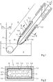
- a furnace-trunk 1 a continuous strip galvanizing (hot dip galvanizing) is outlined.
- a continuous strip galvanizing preferably steel strip
- HNX protective gas
- the band 2 dives obliquely down into the zinc bath 3 and is deflected by a arranged in a zinc bath roller 4 upwards.
- the bath temperature is typically in the range of about 440 to 470 ° C.
- the tape 2 'entrains a quantity of liquid zinc that is significantly above the desired coating thickness.
- the still liquid excess coating material is stripped by means of extending over the bandwidth air jet flat nozzles 5 from the top and bottom (front and back) of the coated strip 2 '.
- the trunk 1 In the oven trunk 1, part of the protective gas is entrained by the belt movement in the direction of the zinc bath 3. In order to prevent the entrained inert gas from absorbing zinc vapor on the zinc bath surface, which deposits on the colder inner wall surfaces of the trench 1 as zinc dust and can cause surface defects on the galvanized belt 2 'in larger pieces on the belt 2 and / or zinc bath 3 falls, the trunk 1 is provided with a special blow-suction device 6.
- the blow-suction device 6 comprises a branched line system 7.1, 7.2 with a plurality of injection and suction 7.11, 7.21, by means of which inert gas in the end of the trunk 1, ie near the zinc bath 3, is circulated so that the tape from the second entrained inert gas stream is interrupted as possible, but without causing increased band vibrations.
- the injection and suction openings 7.11, 7.21 are arranged in the direction of movement of the belt 2 so that each injection opening 7.11 is located in the vicinity of at least one suction opening 7.21, whereby injected inert gas sucked in the immediate vicinity again and thus an uncontrollable turbulence of the protective gas is prevented.
- the blowing suction device 6 comprises an upper part 6.1 and a lower part 6.2, wherein the upper part 6.1 extends over the entire width of the band top side (front side), while the lower part 6.2 extends over the entire width of the band bottom side (back side).
- the upper part 6.1 and the lower part 6.2 may each be box-shaped and accordingly be referred to as a blow-suction box or blow-suction boxes.
- the respective blower suction box (6.1, 6.2) is divided by partitions 7.3 into a branched blow chamber 7.1 'with mutually parallel injection branches 7.10 and a branched suction chamber 7.2' with mutually parallel suction branches 7.20.
- An injection branch 7.10 can lie directly next to a suction branch 7.20 in that both branches 7.10, 7.20 are separated from one another by the same partition 7.3.
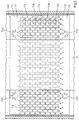
- the subdivision into a branched-off blow chamber 7.1 'and a branched suction chamber 7.2' can be realized, for example, by a meandering or folded partition 7.3 or by meandering partition walls, which are gas-tightly connected to one another at their abutting ends, as in FIG Fig. 5 outlined.
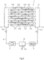
- main chamber sections 7.4 7.5 open fittings 7.41, 7.51 for connecting at least one return line 8, which is connected to a suction fan, suction fan 9 or the like and defines a gas cycle or allows (see. Fig. 3 ).
- the connecting piece 7.51 for extracting the protective gas is below the connecting piece 7.41, via which the protective gas is supplied, arranged (see also Fig. 6 ). This ensures that the flow of the injected inert gas is always or substantially only directed downwards, whereby an influx of zinc vapor from the zinc bath into the trunk 1 is effectively prevented.
- the connecting pieces 7.41 of the upper main chamber section 7.4 are arranged at a distance from each other transversely to the strip running direction.
- the connecting pieces 7.51 of the lower main chamber section 7.5 are spaced apart transversely to the strip running direction.
- the injection and suction branches 7.10, 7.20 are provided with a plurality of openings (nozzles) 7.11, 7.21, which serve as injection openings or suction openings.
- These openings (nozzles) 7.11, 7.21 are arranged or designed such that the protective gas flowing from the injection openings 7.11 at an angle of incidence in the range of 70 ° to 110 °, preferably 80 ° to 100 °, on the surface facing the respective injection opening Bandes 2 is addressed or hits.
- the injection nozzles 7.11 are designed so that the protective gas flowing out of them is directed substantially at right angles to the strip surface (cf. Fig. 2 and 4 ).
- the distance between the respective injection nozzle 7.11 and at least one associated suction opening 7.21 is selected so that at a predetermined or predetermined flow velocity of the injected protective gas occurring during movement of the belt 2 entrainment of protective gas in the direction of the zinc bath 3 is effectively interrupted or at least minimized ,
- the entrainment of protective gas caused by the belt movement contributes to a "natural gas movement".
- the natural gas movement is also driven by the usually existing temperature difference between the entrained by the band 2, relatively hot inert gas above the zinc bath 3 and the colder inert gas in the upper part of the trunk 1.
- the inventive interruption or blocking this natural gas movement is at the same time the entrainment or the transport of zinc vapor from the Zinkbadober Structure 3.1 interrupted in the upper trunk area or at least minimized.
- At least five, preferably at least seven, more preferably at least ten injection openings (nozzles) are 7.11 arranged the width of the band 2 distributed.
- each injection opening 7.11 is at least one suction opening 7.21.
- the injection openings 7.11 and the suction openings 7.21 are arranged in a matrix. The blowing and suction thus takes place in several Steps, preferably in at least three stages.
- the injection openings 7.11 are arranged offset in the strip running direction and over the strip width to the suction openings 7.21 (cf. Fig. 5 ).
- the injection openings 7.11 and the suction openings 7.21 are arranged uniformly spaced from one another.
- a large amount of inert gas can be exchanged via the gas injection channels 7.10 without a large gas transport in the direction of strip travel.
- the band 2 is not excited to vibrate.
- the unwanted transport of zinc vapor from the immersion region of the strip 2 into the upper part of the snout 1 is not supported by the gas flow.
- the trunk cross-section can be completely traversed in the transverse direction.
- Protective gas not yet loaded with zinc dust mixes with shielding gas loaded with zinc dust and is sucked off in the vicinity.
- the blowing suction device 6 or the blowing suction box 6.1, 6.2 can also be designed in such a way that the injection openings 7.11 on tine-like branches 7.10 of a comb-shaped blow pipe formation 7.1 and the suction openings 7.21 on tine-like branches 7.20 of a comb-shaped intake pipe formation 7.2 are formed. wherein the prong-like branches 7.10 of the comb-shaped Blasrohrgechanes 7.1 and the prong-like branches 7.20 of the comb-shaped Saugrohrgestorystoryes 7.2 interlock.
- This configuration allows an adjustment of the distance of the injection openings 7.11 from the suction openings 7.21 by moving the comb-shaped Blasrohrgesches 7.1 relative to the comb-shaped Saugrohrgesente 7.2.
- a zinc separation device 10 for cleaning the protective gas loaded with zinc vapor and / or zinc dust is integrated in the return line 8.
- the zinc separator 10 is preferably provided with a cooling device which effects resublimation of zinc vapor.
- the resulting zinc dust can be separated by means of a separator from the protective gas and passed into a collection container 10.1.
- the purified protective gas stream is heated before blowing by means of a gas heater 11, for example to a temperature in the range of 450 to 600 ° C.
- the trunk 1 with the Blow-suction device or the blow-suction boxes 6.1, 6.2 is heated by this gas flow so that at any point of the trunk 1, the dew point or Resublimationstemperatur of zinc vapor is exceeded.
- the Gaseinblaskanäle 7.10 run along the tape longitudinal axis or Russellssensachse and parallel to the suction lines arranged therebetween 7.20.
- the gas injection channels 7.10 cover a longitudinal section of the strip 2 completely or essentially completely both on the underside of the strip and on the upper side of the strip. This causes a uniform surface temperature of the blowing suction device or blowing suction boxes 6.1, 6.2, wherein the surface temperature is above the dew point or Resublimationstemperatur of zinc vapor.
- the device 6 is designed as a push-pull system.
- hot inert gas is injected with slight overpressure on the injection openings 7.11 in the trunk 1, to generate at the injection openings 7.11 (outlet points) cross flows.
- the injected inert gas stream is set equal to or slightly below the extracted gas flow amount.
- the protective gas flow injected per band side (blower suction box 6.1 or 6.2) is about 150 Nm 3 / h at about 600 ° C., while the protective gas flow drawn off per band side including zinc vapor is about 200 Nm 3 / h.
- the Blasdorfsch (Blaschaupt Arthur) are 7.1 and the Einblaszweige (Gaseinblaskanäle) 7.10 and preferably also the main suction chamber 7.2 and the suction branches (suction lines) 7.20 thermally insulated by a heat insulating layer of the trunk structure.
- the trunk 1 is also provided with an external heat insulation 12 to keep the inside of the trunk walls at a temperature greater than 300 ° C.
- the lowest part of the trunk 1, i. the trunk end piece 1.1 located between the blowing suction device and the zinc bath 3 is preferably provided with a heat insulation 13.
- the thermal insulation 13 ensures that the walls or wall sections of the trunk provided therewith during operation of the galvanizing plant are warmer than the dew point or resublimation temperature of the protective gas / zinc vapor mixture.
- the thermal insulation 13 is formed for example of mineral wool and / or ceramic plates and surrounds the trunk end 1.1 preferably jacket-shaped.
- a further embodiment of the invention provides that the trunk end piece 1.1 is provided with a heating device (not shown) in addition or alternatively to the heat insulation 13.
- the oven trunk 1 designed according to the invention can be divided into three areas A, B and C with respect to the protective gas (cf. Fig. 1 ).
- the area A comprises the end piece 1.1, which is preferably provided with a thermal insulation 13. In this area A occurs a relatively high zinc vapor loading at low gas movement.
- the surface temperature of the snout 1 is above 440 ° C in this area.
- the region A is followed by the region B, which is equipped with the blow-suction device according to the invention (for example in the form of blow-suction boxes 6.1, 6.2).
- the area B serves as a separation lock or gas curtain. It interrupts the "natural gas flow", in particular the entrainment of protective gas in the direction of zinc bath 3 caused by the belt movement, by blowing purified hot inert gas while simultaneously extracting zinc vapor-laden space close to the injection points 7.11.
- the multi-stage arrangement of the injection nozzles 7.11 and suction nozzles 7.21, the zinc vapor concentration is gradually reduced in the area B.
- the surface temperatures of the blower suction boxes 6.1, 6.2 and the insides of the spout 1 are above the dew point or resublimation temperature of zinc vapor, i. above 400 ° C.
- the area C is characterized by a low zinc vapor content in the protective gas.
- the surface temperature of the inside of the trunk is more than 300 ° C. in the region C, which prevents condensation or resublimation of the zinc vapor which is still slightly present there in the protective gas.
Landscapes
- Chemical & Material Sciences (AREA)
- Engineering & Computer Science (AREA)
- Materials Engineering (AREA)
- Mechanical Engineering (AREA)
- Metallurgy (AREA)
- Organic Chemistry (AREA)
- Chemical Kinetics & Catalysis (AREA)
- Physics & Mathematics (AREA)
- Thermal Sciences (AREA)
- Crystallography & Structural Chemistry (AREA)
- Coating With Molten Metal (AREA)
- Heat Treatment Of Strip Materials And Filament Materials (AREA)
Description
- Die Erfindung betrifft ein Verfahren zur Vermeidung von durch Zinkstaub verursachten Oberflächenfehlern an verzinktem Metallband in einer kontinuierlichen Bandverzinkung, bei der in einem Durchlaufofen erhitztes Metallband unter Schutzgas durch einen Ofen-Rüssel hindurchbewegt und in ein Zinkbad eingetaucht wird, gemäß dem Oberbegriff des Anspruchs 1. Ferner betrifft die Erfindung eine Vorrichtung zur Vermeidung von durch Zinkstaub verursachten Oberflächenfehlern an verzinktem Metallband in einer kontinuierlichen Bandverzinkung, gemäß dem Oberbegriff des Anspruchs 7.
- Eine Anlage zur kontinuierlichen Feuerverzinkung von Stahlband besteht unter anderem aus einem Durchlaufofen, einem Zinkbad (Schmelzbad), einer Vorrichtung zur Einstellung der Zinküberzugsdicke und einer nachfolgenden Kühleinrichtung. In dem Durchlaufofen wird das Stahlband kontinuierlich geglüht. Dabei werden durch Rekristallisation des Stahls die gewünschten mechanischen Eigenschaften des Grundwerkstoffs eingestellt. Zudem werden dabei in einer Vorwärmzone gebildete Eisenoxide reduziert. In einer auf den DurchlaufGlühofen folgenden Kühlzone wird das Band unter Schutzgas (HNX) auf eine Temperatur nahe der Schmelzbadtemperatur abgekühlt. Das Schutzgas soll verhindern, dass das geglühte Band vor dem Verzinken oxidiert, wodurch die Haftung der Zinkschicht erheblich verschlechtert würde. Das Schutzgas enthaltende Verbindungsstück zwischen Glühofen und Zinkbad wird Ofen-Rüssel genannt.
- In einem herkömmlichen Ofen-Rüssel einer kontinuierlichen Bandverzinkungsanlage kommt es üblicherweise zu Ablagerungen von Zinkstaub, der insbesondere bei in der Anlage auftretenden Erschütterungen in größeren Stücken auf das Zinkbad und/oder das Stahlband fällt und damit Oberflächenfehler (Verzinkungsfehler) verursacht. Es wurde erkannt, dass das in Richtung des Zinkbades bewegte Stahlband im Rüssel Schutzgas nach unten mitreißt, wobei das mitgerissene Schutzgas an der Zinkbadoberfläche Zinkdampf aufnimmt, welcher beim Aufsteigen des mitgerissenen Schutzgases an den kälteren Innenwänden des Rüssels kondensiert bzw. resublimiert und sich dort als Staub absetzt.
- Aus der
JP 7157853 (A - Mit der aus der
JP 7157853 (A - Der vorliegenden Erfindung liegt die Aufgabe zugrunde, ein Verfahren und eine Vorrichtung der eingangs genannten Art anzugeben, mit dem bzw. der die Aufnahme von Zinkdampf durch das im Ofen-Rüssel enthaltene Schutzgas sowie die Ausbreitung von Zinkdampf im Ofen-Rüssel deutlich minimiert werden kann.
- Gelöst wird diese Aufgabe durch ein Verfahren mit den Merkmalen des Anspruchs 1 bzw. durch eine Vorrichtung mit den Merkmalen des Anspruchs 7.
- Bei dem erfindungsgemäßen Verfahren werden im Ofen-Rüssel ebenfalls die Ober- und die Unterseite des zu verzinkenden Metallbandes (z.B. Stahlbandes) über Einblasöffnungen mit Schutzgas beaufschlagt. Mit Zinkdampf und/oder Zinkstaub beladenes Schutzgas wird über Absaugöffnungen, die beidseitig des Metallbandes benachbart den Einblasöffnungen angeordnet sind, abgesaugt. Erfindungsgemäß wird eine Vielzahl der Einblasöffnungen in der Weise ausgebildet und im Ofen-Rüssel angeordnet, dass das aus diesen Einblasöffnungen strömende Schutzgas mit einem Auftreffwinkel im Bereich von 70° bis 110°, vorzugsweise 80° bis 100°, besonders bevorzugt ca. 90° auf die der jeweiligen Einblasöffnung zugewandte Oberfläche des Metallbandes gerichtet ist. Zudem werden der Abstand zwischen der jeweiligen Einblasöffnung und wenigstens einer ihr zugeordneten Absaugöffnung so gewählt und die Strömungsgeschwindigkeit des aus der jeweiligen Einblasöffnung austretenden Schutzgases so gesteuert, dass einer bei Bewegung des Metall- bzw. Stahlbandes auftretenden Mitnahme von Schutzgas in Richtung des Zinkbades entgegenwirkt wird.
- Bei der erfindungsgemäßen Vorrichtung ist somit der Ofen-Rüssel mit Einblasöffnungen versehen, über die die Oberseite und die Unterseite des Metallbandes mit Schutzgas beaufschlagbar ist, wobei benachbart zu den Einblasöffnungen Absaugöffnungen zum Absaugen von mit Zinkdampf und/oder Zinkstaub beladenem Schutzgas angeordnet sind. Erfindungsgemäß ist dabei eine Vielzahl der Einblasöffnungen in der Weise ausgebildet und im Ofen-Rüssel angeordnet, dass das aus diesen Einblasöffnungen strömende Schutzgas mit einem Auftreffwinkel im Bereich von 70° bis 110°, vorzugsweise 80° bis 100°, besonders bevorzugt ca. 90° auf die der jeweiligen Einblasöffnung zugewandte Oberfläche des Metallbandes gerichtet ist, wobei der Abstand zwischen der jeweiligen Einblasöffnung und wenigstens einer ihr zugeordneten Absaugöffnung so gewählt ist, dass bei einer vorgegebenen oder vorgebbaren Strömungsgeschwindigkeit des aus der jeweiligen Einblasöffnung austretenden Schutzgases einer bei Bewegung des Metallbandes auftretenden Mitnahme von Schutzgas in Richtung des Zinkbades entgegenwirkt wird.
- Die Erfindung basiert auf der Idee, die Strömungsverhältnisse des Schutzgases insbesondere in Bandnähe so zu beeinflussen, dass die erwähnte Mitnahme von Schutzgas minimiert und/oder die Kondensation bzw. Resublimation von Zinkdampf an den Wänden des Rüssels verhindert wird. Im Unterschied zu der aus der
JP 7157853 (A - Eine vorteilhafte Ausgestaltung des erfindungsgemäßen Verfahrens sieht vor, dass das über die Einblasöffnungen zugeführte Schutzgas zuvor auf eine Temperatur von mindestens 500°C, vorzugsweise mindestens 550°C erwärmt wird. Durch diese Ausgestaltung kann die Resublimation von Zinkstaub im Ofen-Rüssel noch effektiver verhindert werden, da der aufgeheizte, über die Einblasöffnungen zugeführte Schutzgasstrom den an der Zinkbadoberfläche entstehenden Zinkdampf im gasförmigen Zustand hält.
- Dementsprechend sieht eine bevorzugte Ausgestaltung der erfindungsgemäßen Vorrichtung vor, dass die Absaugöffnungen über eine mindestens einen Absaugventilator aufweisende Rückführleitung mit den Einblasöffnungen verbunden sind, wobei die Rückführleitung mit mindestens einer Heizeinrichtung zum Erwärmen des Schutzgases auf eine Temperatur von mindestens 500°C, vorzugsweise mindestens 550°C versehen ist.
- Der großflächig und im Wesentlichen über die gesamte Rüsselbreite gleichmäßig in den Rüssel eingetragene Schutzgasstrom stellt dabei gleichzeitig ein Heizmedium für die Blas-/Saugvorrichtung dar und verhindert kalte Zonen im Rüssel, die zu einer Zinkstaub-Ausfällung führen würden. Durch die offenbarte Temperaturführung im Rüsselbereich entsteht erst gar kein sublimierter Zinkstaub im Rüssel. Vielmehr wird der im Schutzgas enthaltene Zinkdampf abgeführt, bevor er zu Staubkörnern sublimieren kann.
- Vorzugsweise wird das erfindungsgemäße Verfahren in der Weise ausgeführt, dass die Temperatur der Gaswolke in dem räumlich höher gelegenen Teil des Rüssels höher ist als die Temperatur im räumlich tiefer gelegenen Eintauchbereich des Bandes. Hierdurch werden thermische Turbulenzen im Rüssel minimiert.
- Eine weitere vorteilhafte Ausgestaltung des erfindungsgemäßen Verfahrens ist dadurch gekennzeichnet, dass das Einblasen von Schutzgas über die Einblasöffnungen und das Absaugen von Schutzgas über die Absaugöffnungen in mindestens drei Stufen durchgeführt wird, die in Bandlaufrichtung aufeinander folgend angeordnet sind, wobei jede der Stufen aus einer Reihe von mindestens fünf, vorzugsweise mindestens sieben Einblasöffnungen und einer Reihe von mindestens fünf, vorzugsweise mindestens sieben Absaugöffnungen gebildet ist. Auf diese Weise lässt sich eine besonders wirksame Sperrung des von dem zu verzinkenden Band mitgerissenen Schutzgases erzielen. Insbesondere lässt sich durch die relativ hohe Anzahl von Einblasöffnungen und Absaugöffnungen eine eher sanfte, turbulenzarme Schutzgas-Blasströmung erzeugen, so dass eine übermäßige, unkontrollierbare Verwirbelung des Schutzgases und erhöhte Bandschwingungen vermieden werden. Durch diese mehrstufige Anordnung der Einblasöffnungen und Absaugöffnungen lassen sich die Konzentration des Zinkdampfes im Schutzgas und damit der Partialdruck des Zinkdampfes stufenweise auf ein unkritisches Maß absenken.
- Zu diesem Zweck sieht eine bevorzugte Ausgestaltung der erfindungsgemäßen Vorrichtung vor, dass die Einblasöffnungen und die Absaugöffnungen in mindestens drei Stufen ausgebildet sind, die in Bandlaufrichtung aufeinander folgend angeordnet sind, wobei jede der Stufen aus einer Reihe von mindestens fünf, vorzugsweise mindestens sieben Einblasöffnungen und einer Reihe von mindestens fünf, vorzugsweise mindestens sieben Absaugöffnungen gebildet ist.
- Eine weitere vorteilhafte Ausgestaltung des erfindungsgemäßen Verfahrens ist dadurch gekennzeichnet, dass der über die Einblasöffnungen zugeführte Schutzgasvolumenstrom gleich dem über die Absaugöffnungen abgesaugten Schutzgasvolumenstrom eingestellt wird oder auf einen Wert eingestellt wird, der maximal 5% unterhalb des abgesaugten Schutzgasvolumenstroms liegt. Durch die gleichen bzw. nahezu gleichen Volumenströme von zugeführtem und abgesaugtem Schutzgas und der erwähnten bevorzugten gleichmäßigen Verteilung von Einblasstellen und Absaugstellen wird die Gasturbulenz im Rüssel auf ein Minimum reduziert.
- Zur Erzielung einer möglichst wirksamen Sperrung oder Unterbrechung des durch das bewegte Metallband mitgerissenen Schutzgasstroms bei gleichzeitiger Minimierung der Verwirbelung des Schutzgases ist es günstig, wenn nach einer weiteren bevorzugten Ausgestaltung der erfindungsgemäßen Vorrichtung die Einblasöffnungen und die Absaugöffnungen matrixförmig angeordnet sind. Auch ist in diesem Zusammenhang günstig, wenn die Einblasöffnungen versetzt zu den Absaugöffnungen - in Bandlaufrichtung sowie über die Bandbreite betrachtet - angeordnet sind. Vorzugsweise sind die Einblasöffnungen und die Absaugöffnungen der erfindungsgemäßen Vorrichtung gleichmäßig voneinander beabstandet angeordnet.
- Der Abstand zwischen der jeweiligen Einblasöffnung (Einblasdüse) und der mindestens einen ihr zugeordneten Absaugöffnung ist vorzugsweise kleiner/gleich 25 cm, insbesondere kleiner 15 cm, und besonders bevorzugt kleiner/gleich 10 cm.
- Zur Verwirklichung einer turbulenzarmen Unterbrechung des durch das bewegte Metallband mitgerissenen Schutzgasstroms bzw. zur Erzielung einer möglichst gleichmäßigen Verteilung der Einblasstellen und Absaugstellen sieht eine weitere bevorzugte Ausgestaltung der erfindungsgemäßen Vorrichtung vor, dass die Einblasöffnungen an zinkenartigen Zweigen eines kammförmigen Blasrohrgebildes und die Absaugöffnungen an zinkenartigen Zweigen eines kammförmigen Saugrohrgebildes ausgebildet sind, wobei die zinkenartigen Zweige des kammförmigen Blasrohrgebildes und die zinkenartigen Zweige des kammförmigen Saugrohrgebildes ineinander greifen.
- Wird dabei der Schutzgasstrom vor dem Einblasen mittels eines Gaserhitzers aufgeheizt, vorzugsweise auf eine Temperatur im Bereich von 450 bis 600°C, so bewirkt die vorstehend genannte Ausgestaltung zugleich, dass sich an dem aus den kammförmigen Rohrgebilden zusammengesetzten Rohrleitungssystem im Betrieb eine sehr gleichmäßige Oberflächentemperaturverteilung einstellt, wobei die Oberflächentemperatur des im Rüssel angeordneten Rohrleitungssystems bei Beheizung des Schutzgasstroms auf eine Temperatur im Bereich von 450 bis 600°C oberhalb der Taupunkt- bzw. Resublimationstemperatur von Zink liegt. Insbesondere verhindert die Erwärmung des Rohrleitungssystems mit aufgeheiztem Schutzgas das Auftreten punktueller Temperaturspitzen und damit eine ungewollte Gaskonvektion bzw. Gasturbulenz.
- In diesem Zusammenhang sieht eine weitere vorteilhafte Ausgestaltung der erfindungsgemäßen Vorrichtung vor, dass das kammförmige Blasrohrgebilde und das kammförmige Saugrohrgebilde durch eine Wärmeisolierung gegenüber dem Ofen-Rüssel thermisch isoliert sind.
- Nach einer weiteren bevorzugten Ausgestaltung des erfindungsgemäßen Verfahrens wird der Ofen-Rüssel zumindest in einem Bereich, der sich vom Zinkbad bis zu den Einblasöffnungen und/oder Absaugöffnungen erstreckt, auf eine Temperatur von mindestens 400°C, vorzugsweise mindestens 450°C beheizt. Ergänzend zu einer dafür vorgesehenen Heizeinrichtung, oder alternativ dazu, kann dieser untere Bereich des Ofen-Rüssels nach einer bevorzugten Ausgestaltung der erfindungsgemäßen Vorrichtung auch mit einer Wärmeisolierung versehen sein. Hierdurch lässt sich erreichen, dass die relevanten Wände oder Wandabschnitte des Ofen-Rüssels wärmer sind als die Temperatur, bei der die Kondensation bzw. Resublimation von Zinkdampf beginnt.
- Weitere bevorzugte und vorteilhafte Ausgestaltungen der Erfindung sind in den beiliegenden Ansprüchen angegeben.
- Nachfolgend wird die Erfindung anhand einer mehrere Ausführungsbeispiele darstellenden Zeichnung näher erläutert. Es zeigen schematisch:
- Fig. 1
- eine Längsschnittansicht eines Abschnitts eines erfindungsgemäß ausgeführten Ofen-Rüssels einer kontinuierlichen Bandverzinkung;
- Fig. 2
- eine Querschnittansicht des Ofen-Rüssels entlang der Schnittlinie II-II in
Fig. 1 ; - Fig. 3
- eine in einem Ofen-Rüssel gemäß
Fig. 1 angeordnete Blas-Saugvorrichtung in Draufsicht mit zugeordneter Rückführleitung, die mit einem Absaugventilator, einer Zinkabscheidevorrichtung und einer Heizeinrichtung zum Erwärmen des von Zink gereinigten, einzublasenden Schutzgases versehen ist; - Fig. 4
- eine weitere Längsschnittansicht eines Abschnitts eines erfindungsgemäß ausgeführten Ofen-Rüssels einer kontinuierlichen Bandverzinkung;
- Fig. 5
- eine Draufsicht auf einen Längsabschnitt des zu verzinkenden Metallbandes in einem Abschnitt des Ofen-Rüssels der
Fig. 4 ; und - Fig. 6
- den Abschnitt des Ofen-Rüssels gemäß
Fig. 4 in einer perspektivischen Darstellung. - In der Zeichnung ist ein Ofen-Rüssel 1 einer kontinuierlichen Bandverzinkung (Feuerverzinkung) skizziert. Ein zu verzinkendes Metallband 2, vorzugsweise Stahlband, wird in einem (nicht gezeigten) Durchlaufofen geglüht und unter Schutzgas (HNX) einem Zinkbad 3 zugeführt. Das Band 2 taucht schräg nach unten in das Zinkbad 3 ein und wird durch eine im Zinkbad angeordnete Rolle 4 nach oben umgelenkt. Die Badtemperatur liegt typischerweise im Bereich von ca. 440 bis 470°C. Beim Austritt aus dem Bad 3 reißt das Band 2' eine flüssige Zinkmenge mit, die erheblich über der gewünschten Überzugsdicke liegt. Das noch flüssige überschüssige Überzugsmaterial wird mittels sich über die Bandbreite erstreckende Luftstrahl-Flachdüsen 5 von Ober- und Unterseite (Vorder- und Rückseite) des beschichteten Bandes 2' abgestreift.
- In dem Ofen-Rüssel 1 wird ein Teil des Schutzgases durch die Bandbewegung in Richtung Zinkbad 3 mitgerissen. Um zu verhindern, dass das mitgerissene Schutzgas an der Zinkbadoberfläche Zinkdampf aufnimmt, welcher sich an den kälteren Innenwandflächen des Rüssels 1 als Zinkstaub absetzt und Oberflächenfehler an dem verzinkten Band 2' verursachen kann, wenn er in größeren Stücken auf das Band 2 und/oder Zinkbad 3 fällt, ist der Rüssel 1 mit einer besonderen Blas-Saugvorrichtung 6 versehen.
- Die erfindungsgemäße Blas-Saugvorrichtung 6 weist ein verzweigtes Leitungssystem 7.1, 7.2 mit einer Vielzahl von Einblas- und Absaugöffnungen 7.11, 7.21 auf, mittels derer Schutzgas im Endbereich des Rüssels 1, d.h. nahe des Zinkbades 3, so umgewälzt wird, dass der vom Band 2 mitgerissene Schutzgasstrom möglichst unterbrochen wird, jedoch ohne dass dadurch erhöhte Bandschwingungen verursacht werden. Zu diesem Zweck sind die Einblas- und Absauföffnungen 7.11, 7.21 in Bewegungsrichtung des Bandes 2 so angeordnet, dass jede Einblasöffnung 7.11 in der Nähe wenigstens einer Absaugöffnung 7.21 liegt, wodurch eingeblasenes Schutzgas in unmittelbarer Umgebung wieder abgesaugt und so eine unkontrollierbare Verwirbelung des Schutzgases verhindert wird.
- Die Blas-Saugvorrichtung 6 umfasst einen oberen Teil 6.1 und einen unteren Teil 6.2, wobei sich der obere Teil 6.1 über die gesamte Breite der Bandoberseite (Vorderseite) erstreckt, während sich der untere Teil 6.2 über die gesamte Breite der Bandunterseite (Rückseite) erstreckt. Der obere Teil 6.1 sowie der untere Teil 6.2 können jeweils kastenartig ausgebildet sein und dementsprechend als Blas-Saugkasten bzw. Blas-Saugkästen bezeichnet werden. Der jeweilige Blas-Saugkasten (6.1, 6.2) ist durch Trennwände 7.3 in eine verzweigte Blaskammer 7.1' mit parallel zueinander verlaufenden Einblaszweigen 7.10 und eine verzweigte Saugkammer 7.2' mit parallel zueinander verlaufenden Saugzweigen 7.20 unterteilt. Ein Einblaszweig 7.10 kann dabei unmittelbar neben einem Saugzweig 7.20 liegen, indem beide Zweige 7.10, 7.20 durch dieselbe Trennwand 7.3 voneinander getrennt sind. Die Unterteilung in eine verzweigte Blaskammer 7.1' und eine verzweigte Saugkammer 7.2' kann beispielsweise durch eine mäanderförmig verlaufende oder gefaltete Trennwand 7.3 bzw. durch mäanderförmig aneinandergesetzte Trennwände, die an ihren aneinander stoßenden Enden gasdicht miteinander verbunden sind, verwirklicht sein, wie in
Fig. 5 skizziert ist. In die quer zur Bandlaufrichtung verlaufenden Hauptkammerabschnitte 7.4, 7.5 münden Anschlussstücke 7.41, 7.51 zum Anschluss mindestens einer Rückführleitung 8, die an einem Sauggebläse, Saugventilator 9 oder dergleichen angeschlossen ist und einen Gaskreislauf definiert bzw. ermöglicht (vgl.Fig. 3 ). - Das Anschlussstück 7.51 zur Absaugung des Schutzgases ist unterhalb des Anschlussstückes 7.41, über welches das Schutzgas zugeführt wird, angeordnet (siehe auch
Fig. 6 ). Dadurch ist sichergestellt, dass die Strömung des eingeblasenen Schutzgases stets oder im Wesentlichen nur nach unten gerichtet ist, wodurch ein Aufströmen von Zinkdampf aus dem Zinkbad in den Rüssel 1 hinein wirksam verhindert wird. - Wie in den
Figuren 5 und6 dargestellt, münden in den oberen Hauptkammerabschnitt 7.4 des jeweiligen Blas-Saugkastens 6.1 bzw. 6.2 vorzugsweise mindestens zwei Anschlussstücke 7.41 zum Einblasen von Schutzgas, während der tiefer angeordnete Hauptkammerabschnitt 7.5 des Blas-Saugkastens 6.1 bzw. 6.2 vorzugsweise mit mindestens zwei Anschlussstücke 7.51 zum Absaugen von mit Zinkdampf beladenem Schutzgas vorgesehen ist. Die Anschlussstücke 7.41 des oberen Hauptkammerabschnitts 7.4 sind dabei quer zur Bandlaufrichtung voneinander beabstandet angeordnet. Ebenso sind die Anschlussstücke 7.51 des unteren Hauptkammerabschnitts 7.5 quer zur Bandlaufrichtung voneinander beabstandet. - Die Einblas- und Saugzweige 7.10, 7.20 sind mit einer Vielzahl von Öffnungen (Düsen) 7.11, 7.21 versehen, die als Einblasöffnungen bzw. Absaugöffnungen dienen. Diese Öffnungen (Düsen) 7.11, 7.21 sind so angeordnet bzw. ausgeführt, dass das aus den Einblasöffnungen 7.11 strömende Schutzgas mit einem Auftreffwinkel im Bereich von 70° bis 110°, vorzugsweise 80° bis 100°, auf die der jeweiligen Einblasöffnung zugewandte Oberfläche des Bandes 2 gerichtet ist bzw. trifft. Vorzugsweise sind die Einblasdüsen 7.11 so ausgeführt, dass das aus ihnen ausströmende Schutzgas im Wesentlichen rechtwinklig auf die Bandoberfläche gerichtet ist (vgl.
Fig. 2 und4 ). Der Abstand zwischen der jeweiligen Einblasdüse 7.11 und wenigstens einer ihr zugeordneten Absaugöffnung 7.21 ist dabei so gewählt, dass bei einer vorgegebenen oder vorgebbaren Strömungsgeschwindigkeit des eingeblasenen Schutzgases die bei Bewegung des Bandes 2 auftretende Mitnahme von Schutzgas in Richtung des Zinkbades 3 wirksam unterbrochen oder zumindest minimiert wird. - Die durch die Bandbewegung hervorgerufene Mitnahme von Schutzgas trägt zu einer "natürlichen Gasbewegung" bei. Angetrieben wird die natürliche Gasbewegung zudem durch den üblicherweise vorhandenen Temperaturunterschied zwischen dem durch das Band 2 mitgerissenen, relativ heißen Schutzgas oberhalb des Zinkbades 3 und dem kälteren Schutzgas im oberen Bereich des Rüssels 1. Durch die erfindungsgemäße Unterbrechung oder Sperrung dieser natürlichen Gasbewegung wird zugleich die Mitnahme bzw. der Transport von Zinkdampf von der Zinkbadoberfläche 3.1 in den oberen Rüsselbereich unterbrochen oder zumindest minimiert.
- Um eine möglichst gleichmäßige Sperrwirkung für die Gasbewegung in Bandlaufrichtung sowie für die aufwärtsgerichtete Gasbewegung entlang der Innenseite der Rüsselwände zu erzielen, ohne dass es dabei zu erhöhten Bandschwingungen kommt, sind mindestens fünf, vorzugsweise mindestens sieben, besonders bevorzugt mindestens zehn Einblasöffnungen (Düsen) 7.11 über die Breite des Bandes 2 verteilt angeordnet.
- In unmittelbarer Nähe zu jeder Einblasöffnung 7.11 befindet sich mindestens eine Absaugöffnung 7.21. Die Einblasöffnungen 7.11 und die Absaugöffnungen 7.21 sind matrixförmig angeordnet. Das Einblasen und Absaugen erfolgt somit in mehreren Stufen, vorzugsweise in mindestens drei Stufen. Die Einblasöffnungen 7.11 sind dabei in Bandlaufrichtung sowie über die Bandbreite betrachtet versetzt zu den Absaugöffnungen 7.21 angeordnet (vgl.
Fig. 5 ). Vorzugsweise sind die Einblasöffnungen 7.11 und die Absaugöffnungen 7.21 gleichmäßig voneinander beabstandet angeordnet. - Über die Gaseinblaskanäle 7.10 kann eine große Menge Schutzgas ausgetauscht werden, ohne dass ein großer Gastransport in Bandlaufrichtung erfolgt. In vorteilhafter Weise wird hierdurch das Band 2 nicht zu Schwingungen angeregt. Gleichzeitig wird durch die Gasströmung der unerwünschte Transport von Zinkdampf aus dem Eintauchbereich des Bandes 2 in den oberen Teil des Rüssels 1 nicht unterstützt.
- Durch die abwechselnde Anordnung von Einblasdüsen 7.11 und Saugdüsen 7.21 (
Fig. 3 ) kann der Rüsselquerschnitt vollständig in Querrichtung durchströmt werden. Noch nicht mit Zinkstaub beladenes Schutzgas mischt sich mit Zinkstaub beladenem Schutzgas und wird in räumlicher Nähe abgesaugt. - Wie in
Fig. 3 skizziert ist, kann die Blas-Saugvorrichtung 6 bzw. der Blas-Saugkasten 6.1, 6.2 auch dergestalt ausgeführt werden, dass die Einblasöffnungen 7.11 an zinkenartigen Zweigen 7.10 eines kammförmigen Blasrohrgebildes 7.1 und die Absaugöffnungen 7.21 an zinkenartigen Zweigen 7.20 eines kammförmigen Saugrohrgebildes 7.2 ausgebildet sind, wobei die zinkenartigen Zweige 7.10 des kammförmigen Blasrohrgebildes 7.1 und die zinkenartigen Zweige 7.20 des kammförmigen Saugrohrgebildes 7.2 ineinander greifen. Diese Ausgestaltung ermöglicht eine Justierung des Abstandes der Einblasöffnungen 7.11 von den Absaugöffnungen 7.21 durch Verschieben des kammförmigen Blasrohrgebildes 7.1 relativ zu dem kammförmigen Saugrohrgebilde 7.2. - In der Rückführleitung 8 ist außer dem Sauggebläse oder Saugventilator 9 eine Zinkabscheidevorrichtung 10 zur Reinigung des mit Zinkdampf und/oder Zinkstaub beladenen Schutzgases integriert. Die Zinkabscheidevorrichtung 10 ist vorzugsweise mit einer Kühleinrichtung versehen, die eine Resublimation von Zinkdampf bewirkt. Der dadurch entstehende Zinkstaub kann mittels einer Trenneinrichtung vom Schutzgas abgetrennt und in einen Sammelbehälter 10.1 geleitet werden.
- Das stufenweise Einblasen von gereinigtem bzw. unbeladenem Schutzgas und das in unmittelbarer Nähe zu den Einblasstellen erfolgende Absaugen von mit Zinkdampf und/oder Zinkstaub beladenem Schutzgas senkt die Konzentration des Zinkdampfes und/oder Zinkstaubes in dem im Rüssel 1 befindlichen Schutzgas und damit den Partialdruck des Zinkdampfes stufenweise auf ein unkritisches Maß ab. Die stufenweise Verminderung des Gehaltes an Zinkdampf und Zinkstaub in dem damit beladenen Schutzgas ist in
Fig. 4 schematisch skizziert, wobei die schlangenförmigen Pfeile Z für Zinkdampf stehen, die geradlinigen Pfeile G die Strömungsrichtung des Schutzgases im Rüssel 1 und in der Blas-Absaugvorrichtung (Blas-Saugkasten) anzeigen und die "Punktwolken" D Zinkstaub darstellen. Es ist zu erkennen, dass der Gehalt an Zinkdampf und Zinkstaub von der Zinkbadoberfläche 3.1 in Richtung Glühofen stufenweise abnimmt. - Der gereinigte Schutzgasstrom wird vor dem Einblasen mittels eines Gaserhitzers 11 aufgeheizt, beispielsweise auf eine Temperatur im Bereich von 450 bis 600°C. Der Rüssel 1 mit der Blas-Saugvorrichtung bzw. den Blas-Saugkästen 6.1, 6.2 wird durch diesen Gasstrom so aufgeheizt, dass an keiner Stelle des Rüssels 1 die Taupunkt- bzw. Resublimationstemperatur von Zinkdampf unterschritten wird.
- Die Gaseinblaskanäle 7.10 verlaufen entlang der Bandlängsachse bzw. Rüssellängsachse und parallel zu den dazwischen angeordneten Absaugleitungen 7.20. In Kombination mit den Absaugleitungen 7.20 überdecken die Gaseinblaskanäle 7.10 einen Längsabschnitt des Bandes 2 vollständig oder im Wesentlichen vollständig sowohl auf der Bandunterseite als auch auf der Bandoberseite. Dies bewirkt eine gleichmäßige Oberflächentemperatur der Blas-Saugvorrichtung bzw. Blas-Saugkästen 6.1, 6.2, wobei die Oberflächentemperatur oberhalb der Taupunkt- bzw. Resublimationstemperatur von Zinkdampf liegt.
- Die erfindungsgemäße Vorrichtung 6 ist als Druck-Zug-System (Push-Pull-System) ausgeführt. Dabei wird heißes Schutzgas mit leichtem Überdruck über die Einblasöffnungen 7.11 in den Rüssel 1 eingeblasen, um an den Einblasöffnungen 7.11 (Auslassstellen) Querströmungen zu erzeugen. Über eine Mess- und Regeleinrichtung wird der eingeblasene Schutzgasstrom gleich oder geringfügig unterhalb der abgesaugten Gasstrommenge eingestellt. Beispielsweise beträgt der pro Bandseite (Blas-Saugkasten 6.1 oder 6.2) eingeblasene Schutzgasstrom etwa 150 Nm3/h bei ca. 600°C, während der pro Bandseite abgesaugte Schutzgasstrom einschließlich Zinkdampf ca. 200 Nm3/h beträgt.
- Um Wärmeverluste zu minimieren, sind die Blashauptkammer (Blashauptleitung) 7.1 und die Einblaszweige (Gaseinblaskanäle) 7.10 und vorzugsweise auch die Absaughauptkammer 7.2 und die Saugzweige (Absaugleitungen) 7.20 durch eine Wärmeisolierschicht von der Rüsselkonstruktion thermisch isoliert. Der Rüssel 1 ist zudem mit einer äußeren Wärmeisolierung 12 versehen, um die Innenseite der Rüsselwände auf eine Temperatur größer 300°C zu halten.
- Der unterste Teil des Rüssels 1, d.h. das zwischen der Blas-Saugvorrichtung und dem Zinkbad 3 befindlich Rüsselendstück 1.1 ist vorzugsweise mit einer Wärmeisolierung 13 versehen. Die Wärmeisolierung 13 stellt sicher, dass die damit versehenen Wände bzw. Wandabschnitte des Rüssels im Betrieb der Verzinkungsanlage wärmer sind als die Taupunkt- bzw. Resublimationstemperatur des Schutzgas-Zinkdampf-Gemisches. Die Wärmeisolierung 13 ist beispielsweise aus Mineralwolle- und/oder Keramikplatten gebildet und umgibt das Rüsselendstück 1.1 vorzugsweise mantelförmig.
- Ferner sieht eine weitere Ausgestaltung der Erfindung vor, dass das Rüsselendstück 1.1 ergänzend oder alternativ zu der Wärmeisolierung 13 mit einer Heizeinrichtung (nicht gezeigt) versehen ist.
- Der erfindungsgemäß ausgeführte Ofen-Rüssel 1 lässt sich in Bezug auf das Schutzgas in drei Bereiche A, B und C gliedern (vgl.
Fig. 1 ). - Der Bereich A umfasst das Endstück 1.1, das vorzugsweise mit einer Wärmeisolierung 13 versehen ist. In diesem Bereich A tritt eine relativ hohe Zinkdampfbeladung bei geringer Gasbewegung auf. Die Oberflächentemperatur des Rüssels 1 liegt in diesem Bereich oberhalb von 440°C.
- An den Bereich A schließt sich der Bereich B an, der mit der erfindungsgemäßen Blas-Saugvorrichtung (z.B. in Form der Blas-Saugkästen 6.1, 6.2) ausgerüstet ist. Der Bereich B dient als Trennschleuse oder Gasschleier. Er unterbricht den "natürlichen Gasstrom", insbesondere die durch die Bandbewegung verursachte Mitnahme von Schutzgas in Richtung Zinkbad 3, durch Einblasung von gereinigtem heißem Schutzgas bei gleichzeitiger Absaugung von mit Zinkdampf beladenem in räumlicher Nähe zu den Einblasstellen 7.11. Durch die mehrstufige Anordnung der Einblasdüsen 7.11 und Absaugdüsen 7.21 wird die Zinkdampfkonzentration stufenweise im Bereich B reduziert. Die Oberflächentemperaturen der Blas-Saugkästen 6.1, 6.2 und der Innenseiten des Rüssels 1 liegen oberhalb der Taupunkt- bzw. Resublimationstemperatur von Zinkdampf, d.h. oberhalb von 400°C.
- Oberhalb des Bereichs B folgt der Bereich C. Der Bereich C zeichnet sich durch einen geringen Zinkdampfgehalt im Schutzgas aus. Die Oberflächentemperatur der Rüsselinnenseite beträgt im Bereich C mehr als 300°C, wodurch eine Kondensation bzw. Resublimation des dort im Schutzgas noch geringfügig vorhandenen Zinkdampfes verhindert wird.
- Die Ausführung der Erfindung ist nicht auf die vorstehend beschriebenen Ausführungsbeispiele beschränkt. Vielmehr sind zahlreiche Varianten möglich, die auch bei von den in der Zeichnung dargestellten Ausführungsbeispielen abweichender Gestaltung von der in den beiliegenden Patentansprüchen angegebenen Erfindung Gebrauch machen. So können beispielsweise die parallel zueinander verlaufenden Einblaszweige 7.10 und Saugzweige 7.20 des Blas-Saugkastens 6.1, 6.2 bzw. die "Zinken" des kammförmigen Blasrohrgebildes 7.1 sowie des kammförmigen Saugrohrgebildes 7.2 auch quer zur Bandlaufrichtung ausgerichtet werden. Welche dieser Varianten realisiert wird, hängt vom Verlauf der Hauptleitungen für die Schutzgaszufuhr und -absaugung in Bezug auf die Orientierung des Rüssels 1 bzw. den diesbezüglichen Montagemöglichkeiten ab.
Claims (16)
- Verfahren zur Vermeidung von durch Zinkstaub verursachten Oberflächenfehlern an verzinktem Metallband in einer kontinuierlichen Bandverzinkung, bei dem in einem Durchlaufglühofen erhitztes Metallband (2) unter Schutzgas durch einen Ofen-Rüssel (1) hindurchbewegt und in ein Zinkbad (3) eingetaucht wird, bei dem im Ofen-Rüssel (1) die Oberseite und die Unterseite des Metallbandes (2) über Einblasöffnungen (7.11) mit Schutzgas beaufschlagt werden, und bei dem mit Zinkdampf und/oder Zinkstaub beladenes Schutzgas über Absaugöffnungen (7.21), die beidseitig des Metallbandes (2) benachbart den Einblasöffnungen (7.11) angeordnet sind, abgesaugt wird, dadurch gekennzeichnet, dass eine Vielzahl der Einblasöffnungen (7.11) in der Weise ausgebildet und im Ofen-Rüssel (1) angeordnet wird, dass das aus diesen Einblasöffnungen (7.11) strömende Schutzgas mit einem Auftreffwinkel im Bereich von 70° bis 110°, vorzugsweise 80° bis 100°, auf die der jeweiligen Einblasöffnung (7.11) zugewandte Oberfläche des Metallbandes (2) gerichtet ist, wobei der Abstand zwischen der jeweiligen Einblasöffnung (7.11) und wenigstens einer ihr zugeordneten Absaugöffnung (7.21) so gewählt wird und die Strömungsgeschwindigkeit des aus der jeweiligen Einblasöffnung (7.11) austretenden Schutzgases so gesteuert wird, dass einer bei Bewegung des Metallbandes (2) auftretenden Mitnahme von Schutzgas in Richtung des Zinkbades (3) entgegenwirkt wird.
- Verfahren nach Anspruch 1, dadurch gekennzeichnet, dass das über die Einblasöffnungen (7.11) zugeführte Schutzgas zuvor auf eine Temperatur von mindestens 500°C, vorzugsweise mindestens 550°C erwärmt wird.
- Verfahren nach Anspruch 1 oder 2, dadurch gekennzeichnet, dass das Einblasen von Schutzgas über die Einblasöffnungen (7.11) und das Absaugen von Schutzgas über die Absaugöffnungen (7.21) in mindestens drei Stufen durchgeführt wird, die in Bandlaufrichtung aufeinander folgend angeordnet sind, wobei jede der Stufen aus einer Reihe von mindestens fünf, vorzugsweise mindestens sieben Einblasöffnungen (7.11) und einer Reihe von mindestens fünf, vorzugsweise mindestens sieben Absaugöffnungen (7.21) gebildet ist.
- Verfahren nach einem der Ansprüche 1 bis 3, dadurch gekennzeichnet, dass der Ofen-Rüssel (1) zumindest in einem Bereich, der sich vom Zinkbad (3) bis zu den Einblasöffnungen (7.11) und/oder Absaugöffnungen (7.21) erstreckt, auf eine Temperatur von mindestens 400°C beheizt wird.
- Verfahren nach einem der Ansprüche 1 bis 4, dadurch gekennzeichnet, dass der über die Einblasöffnungen (7.11) zugeführte Schutzgasvolumenstrom gleich dem über die Absaugöffnungen (7.21) abgesaugten Schutzgasvolumenstrom eingestellt wird oder auf einen Wert eingestellt wird, der maximal 5% unterhalb des abgesaugten Schutzgasvolumenstroms liegt.
- Verfahren nach einem der Ansprüche 1 bis 5, dadurch gekennzeichnet, dass das abgesaugte, mit Zinkdampf und/oder Zinkstaub beladene Schutzgas mittels einer Zinkabscheidevorrichtung (10) gereinigt wird.
- Vorrichtung zur Vermeidung von durch Zinkstaub verursachten Oberflächenfehlern an verzinktem Metallband in einer kontinuierlichen Bandverzinkung, bei der zu verzinkendes, in einem Durchlaufglühofen erhitztes Metallband (2) unter Schutzgas durch einen Ofen-Rüssel (1) hindurchbewegt und in ein Zinkbad (3) eingetaucht wird, wobei der Ofen-Rüssel (1) mit Einblasöffnungen (7.11) versehen ist, über die die Oberseite und die Unterseite des Metallbandes (2) mit Schutzgas beaufschlagbar ist, und wobei benachbart zu den Einblasöffnungen (7.11) Absaugöffnungen (7.21) zum Absaugen von mit Zinkdampf und/oder Zinkstaub beladenem Schutzgas angeordnet sind, dadurch gekennzeichnet, dass eine Vielzahl der Einblasöffnungen (7.11) in der Weise ausgebildet und im Ofen-Rüssel (1) angeordnet ist, dass das aus diesen Einblasöffnungen (7.11) strömende Schutzgas mit einem Auftreffwinkel im Bereich von 70° bis 110°, vorzugsweise 80° bis 100°, auf die der jeweiligen Einblasöffnung (7.11) zugewandte Oberfläche des Metallbandes (2) gerichtet ist, wobei der Abstand zwischen der jeweiligen Einblasöffnung (7.11) und wenigstens einer ihr zugeordneten Absaugöffnung (7.21) so gewählt ist, dass bei einer vorgegebenen oder vorgebbaren Strömungsgeschwindigkeit des aus der jeweiligen Einblasöffnung (7.11) austretenden Schutzgases einer bei Bewegung des Metallbandes (2) auftretenden Mitnahme von Schutzgas in Richtung des Zinkbades (3) entgegenwirkt wird.
- Vorrichtung nach Anspruch 7, dadurch gekennzeichnet, dass die Absaugöffnungen (7.21) über eine mindestens einen Absaugventilator (9) aufweisende Rückführleitung (8) mit den Einblasöffnungen (7.11) verbunden sind, wobei die Rückführleitung (8) mit mindestens einer Heizeinrichtung (11) zum Erwärmen des Schutzgases auf eine Temperatur von mindestens 500°C, vorzugsweise mindestens 550°C versehen ist.
- Vorrichtung nach Anspruch 8, dadurch gekennzeichnet, dass die Rückführleitung (8) mit einer Zinkabscheidevorrichtung (10) versehen ist.
- Vorrichtung nach Anspruch 7 bis 9, dadurch gekennzeichnet, dass die Einblasöffnungen (7.11) zum Einblasen von Schutzgas und die Absaugöffnungen (7.21) zum Absaugen von Schutzgas in mindestens drei Stufen ausgebildet sind, die in Bandlaufrichtung aufeinander folgend angeordnet sind, wobei jede der Stufen aus einer Reihe von mindestens fünf, vorzugsweise mindestens sieben Einblasöffnungen (7.11) und einer Reihe von mindestens fünf, vorzugsweise mindestens sieben Absaugöffnungen (7.21) gebildet ist.
- Vorrichtung nach einem der Ansprüche 7 bis 10, dadurch gekennzeichnet, dass die Einblasöffnungen (7.11) und die Absaugöffnungen (7.21) matrixförmig angeordnet sind.
- Vorrichtung nach einem der Ansprüche 7 bis 11, dadurch gekennzeichnet, dass die Einblasöffnungen (7.11) in Bandlaufrichtung und über die Bandbreite betrachtet versetzt zu den Absaugöffnungen (7.21) angeordnet sind.
- Vorrichtung nach einem der Ansprüche 7 bis 12, dadurch gekennzeichnet, dass die Einblasöffnungen (7.11) und die Absaugöffnungen (7.21) gleichmäßig voneinander beabstandet angeordnet sind.
- Vorrichtung nach einem der Ansprüche 7 bis 13, dadurch gekennzeichnet, dass die Einblasöffnungen (7.21) an zinkenartigen Zweigen (7.10) eines kammförmigen Blasrohrgebildes (7.1) und die Absaugöffnungen (7.21) an zinkenartigen Zweigen (7.20) eines kammförmigen Saugrohrgebildes (7.2) ausgebildet sind, wobei die zinkenartigen Zweige (7.10) des kammförmigen Blasrohrgebildes (7.1) und die zinkenartigen Zweige (7.20) des kammförmigen Saugrohrgebildes (7.2) ineinander greifen.
- Vorrichtung nach Anspruch 14, dadurch gekennzeichnet, dass das kammförmige Blasrohrgebilde (7.1) und das kammförmige Saugrohrgebilde (7.2) durch eine Wärmeisolierung gegenüber dem Ofen-Rüssel (1) thermisch isoliert sind.
- Vorrichtung nach einem der Ansprüche 7 bis 15, dadurch gekennzeichnet, dass der Ofen-Rüssel (1) zumindest in einem Bereich (1.1, A), der sich vom Zinkbad (3) bis zu den Einblasöffnungen (7.11) und/oder Absaugöffnungen (7.21) erstreckt, mit einer Wärmeisolierung (13) und/oder Heizeinrichtung versehen ist.
Priority Applications (1)
| Application Number | Priority Date | Filing Date | Title |
|---|---|---|---|
| PL13735251T PL2870268T3 (pl) | 2012-07-06 | 2013-07-05 | Sposób i urządzenie do zapobiegania wadom powierzchni wywoływanym przez pył cynkowy podczas cynkowania taśm metodą ciągłą |
Applications Claiming Priority (2)
| Application Number | Priority Date | Filing Date | Title |
|---|---|---|---|
| DE102012106106.8A DE102012106106A1 (de) | 2012-07-06 | 2012-07-06 | Verfahren und Vorrichtung zur Vermeidung von durch Zinkstaub verursachten Oberflächenfehlern in einer kontinuierlichen Bandverzinkung |
| PCT/EP2013/064249 WO2014006183A1 (de) | 2012-07-06 | 2013-07-05 | Verfahren und vorrichtung zur vermeidung von durch zinkstaub verursachten oberflächenfehlern in einer kontinuierlichen bandverzinkung |
Publications (3)
| Publication Number | Publication Date |
|---|---|
| EP2870268A1 EP2870268A1 (de) | 2015-05-13 |
| EP2870268B1 true EP2870268B1 (de) | 2016-09-07 |
| EP2870268B2 EP2870268B2 (de) | 2022-11-30 |
Family
ID=48782310
Family Applications (1)
| Application Number | Title | Priority Date | Filing Date |
|---|---|---|---|
| EP13735251.4A Not-in-force EP2870268B2 (de) | 2012-07-06 | 2013-07-05 | Verfahren und vorrichtung zur vermeidung von durch zinkstaub verursachten oberflächenfehlern in einer kontinuierlichen bandverzinkung |
Country Status (6)
| Country | Link |
|---|---|
| US (1) | US9695496B2 (de) |
| EP (1) | EP2870268B2 (de) |
| DE (1) | DE102012106106A1 (de) |
| ES (1) | ES2605829T5 (de) |
| PL (1) | PL2870268T3 (de) |
| WO (1) | WO2014006183A1 (de) |
Cited By (2)
| Publication number | Priority date | Publication date | Assignee | Title |
|---|---|---|---|---|
| DE202017101798U1 (de) | 2017-03-28 | 2018-06-01 | Schuh Anlagentechnik Gmbh | Mischabscheider für heiße Gase sowie Verzinkungsanlage mit wenigstens einem solchen Mischabscheider |
| DE102017106678A1 (de) | 2017-03-28 | 2018-10-04 | Schuh Anlagentechnik Gmbh | Mischabscheider für heiße Gase sowie Verzinkungsanlage mit wenigstens einem solchen Mischabscheider |
Families Citing this family (11)
| Publication number | Priority date | Publication date | Assignee | Title |
|---|---|---|---|---|
| JP6256325B2 (ja) * | 2014-12-15 | 2018-01-10 | Jfeスチール株式会社 | 連続溶融亜鉛めっき方法及び連続溶融亜鉛めっき設備 |
| DE102015108334B3 (de) * | 2015-05-27 | 2016-11-24 | Thyssenkrupp Ag | Vorrichtung und Verfahren zur verbesserten Metalldampfabsaugung bei einem kontinuierlichen Schmelztauchverfahren |
| CN105063535A (zh) * | 2015-08-04 | 2015-11-18 | 江苏捷帝机器人股份有限公司 | 一种机械人关节轴镀锌装置 |
| BE1023837B1 (fr) * | 2016-01-29 | 2017-08-09 | Centre De Recherches Metallurgiques Asbl | Dispositif pour la stabilisation hydrodynamique d'une bande metallique en defilement continu |
| WO2018228662A1 (de) | 2017-06-12 | 2018-12-20 | Thyssenkrupp Steel Europe Ag | Rüssel für eine schmelztauchbeschichtungsanlage |
| CN110832104B (zh) * | 2017-06-12 | 2021-11-23 | 蒂森克虏伯钢铁欧洲股份公司 | 用于气体气氛分离的装置和方法 |
| WO2018228661A1 (de) | 2017-06-12 | 2018-12-20 | Thyssenkrupp Steel Europe Ag | Rüssel für eine schmelztauchbeschichtungsanlage sowie verfahren für dessen betrieb |
| DE102018211182A1 (de) * | 2018-07-06 | 2020-01-09 | Thyssenkrupp Ag | Vorrichtung und Verfahren zum Schmelztauchbeschichten eines Metallbandes |
| CN110358999B (zh) * | 2019-08-15 | 2021-08-24 | 武汉钢铁有限公司 | 一种具有锌灰喷吹放散处理功能的热镀锌炉鼻子 |
| US12618132B2 (en) * | 2021-07-14 | 2026-05-05 | Jfe Steel Corporation | Method for manufacturing hot-dip galvanized steel sheet |
| WO2024088875A1 (en) * | 2022-10-25 | 2024-05-02 | Tata Steel Ijmuiden B.V. | A method for providing a hnx gas in a snout in a hot dip coating device and a snout |
Citations (5)
| Publication number | Priority date | Publication date | Assignee | Title |
|---|---|---|---|---|
| JPH07157853A (ja) | 1993-12-06 | 1995-06-20 | Nippon Steel Corp | 溶融金属めっきのスナウト内亜鉛ヒューム除去方法及び装置 |
| JPH07316760A (ja) | 1994-05-30 | 1995-12-05 | Nisshin Steel Co Ltd | 連続溶融めっきにおけるスナウト内ドロス発生防止装置 |
| JPH09228016A (ja) | 1996-02-23 | 1997-09-02 | Kawasaki Steel Corp | 溶融金属めっき方法及びその装置 |
| JPH11302811A (ja) | 1998-04-17 | 1999-11-02 | Nippon Steel Corp | 連続亜鉛メッキ設備の炉内雰囲気ガス制御装置 |
| KR20030049330A (ko) | 2001-12-14 | 2003-06-25 | 주식회사 포스코 | 소둔로 스나우트의 아연재 흡입 및 가스 분사장치 |
Family Cites Families (3)
| Publication number | Priority date | Publication date | Assignee | Title |
|---|---|---|---|---|
| JPH07157854A (ja) * | 1993-12-06 | 1995-06-20 | Nippon Steel Corp | 溶融金属めっきのスナウト内清浄化方法及び装置 |
| CA2336373C (en) * | 1999-02-22 | 2007-02-27 | Nippon Steel Corporation | High strength galvanized steel plate excellent in adhesion of plated metal and formability in press working and high strength alloy galvanized steel plate and method for production thereof |
| CN1985016B (zh) * | 2003-01-15 | 2011-09-14 | 新日本制铁株式会社 | 高强度热浸镀锌钢板及其制备方法 |
-
2012
- 2012-07-06 DE DE102012106106.8A patent/DE102012106106A1/de not_active Withdrawn
-
2013
- 2013-07-05 ES ES13735251T patent/ES2605829T5/es active Active
- 2013-07-05 US US14/412,929 patent/US9695496B2/en not_active Expired - Fee Related
- 2013-07-05 PL PL13735251T patent/PL2870268T3/pl unknown
- 2013-07-05 WO PCT/EP2013/064249 patent/WO2014006183A1/de not_active Ceased
- 2013-07-05 EP EP13735251.4A patent/EP2870268B2/de not_active Not-in-force
Patent Citations (5)
| Publication number | Priority date | Publication date | Assignee | Title |
|---|---|---|---|---|
| JPH07157853A (ja) | 1993-12-06 | 1995-06-20 | Nippon Steel Corp | 溶融金属めっきのスナウト内亜鉛ヒューム除去方法及び装置 |
| JPH07316760A (ja) | 1994-05-30 | 1995-12-05 | Nisshin Steel Co Ltd | 連続溶融めっきにおけるスナウト内ドロス発生防止装置 |
| JPH09228016A (ja) | 1996-02-23 | 1997-09-02 | Kawasaki Steel Corp | 溶融金属めっき方法及びその装置 |
| JPH11302811A (ja) | 1998-04-17 | 1999-11-02 | Nippon Steel Corp | 連続亜鉛メッキ設備の炉内雰囲気ガス制御装置 |
| KR20030049330A (ko) | 2001-12-14 | 2003-06-25 | 주식회사 포스코 | 소둔로 스나우트의 아연재 흡입 및 가스 분사장치 |
Cited By (2)
| Publication number | Priority date | Publication date | Assignee | Title |
|---|---|---|---|---|
| DE202017101798U1 (de) | 2017-03-28 | 2018-06-01 | Schuh Anlagentechnik Gmbh | Mischabscheider für heiße Gase sowie Verzinkungsanlage mit wenigstens einem solchen Mischabscheider |
| DE102017106678A1 (de) | 2017-03-28 | 2018-10-04 | Schuh Anlagentechnik Gmbh | Mischabscheider für heiße Gase sowie Verzinkungsanlage mit wenigstens einem solchen Mischabscheider |
Also Published As
| Publication number | Publication date |
|---|---|
| US20150167138A1 (en) | 2015-06-18 |
| DE102012106106A1 (de) | 2014-09-18 |
| ES2605829T5 (es) | 2023-03-16 |
| ES2605829T3 (es) | 2017-03-16 |
| EP2870268A1 (de) | 2015-05-13 |
| US9695496B2 (en) | 2017-07-04 |
| WO2014006183A1 (de) | 2014-01-09 |
| EP2870268B2 (de) | 2022-11-30 |
| PL2870268T3 (pl) | 2017-07-31 |
Similar Documents
| Publication | Publication Date | Title |
|---|---|---|
| EP2870268B2 (de) | Verfahren und vorrichtung zur vermeidung von durch zinkstaub verursachten oberflächenfehlern in einer kontinuierlichen bandverzinkung | |
| DE4336364C2 (de) | Vorrichtung zum Erhitzen oder zum Kühlen von tafelförmigem oder bandförmigem Behandlungsgut aus Glas oder keramischem Werkstoff | |
| EP3303650B1 (de) | Vorrichtung und verfahren zur verbesserten metalldampfabsaugung in einem kontinuierlichen schmelztauchverfahren | |
| DE69708482T2 (de) | Durchlaufglühverfahren von Metallband in verschiedenen Schutzgasen und Vorrichtung | |
| EP1390680B1 (de) | Reaktor mit gasabschluss mittels gasleitkörpern | |
| DE3638426C2 (de) | Verfahren und Vorrichtung zur Ausbildung eines Metalloxidüberzuges auf einem heißen Glassubstrat | |
| EP3632640B1 (de) | Behandlungsanlage für eine durch einen behandlungsofen hindurchführbare flexible materialbahn, insbesondere kunststofffolie | |
| DE2360949A1 (de) | Verfahren und vorrichtung zum abscheiden eines metalloxydfilms auf ein glasband | |
| DE1809859B2 (de) | Verfahren zum haerten von flachen glasscheiben und vorrichtung zur durchfuehrung des verfahrens | |
| AT511034B1 (de) | Verfahren zum kontrollieren einer schutzgasatmosphäre in einer schutzgaskammer zur behandlung eines metallbandes | |
| DE4234855B4 (de) | Aluminiumhartlötverfahren und Ofen dafür | |
| DE19747018A1 (de) | Vorrichtung zur Wärmebehandlung von Werkstücken | |
| DE941384C (de) | Verfahren und Vorrichtung zur Herstellung von Fasern aus faserbildenden Werkstoffen | |
| DE2618168C3 (de) | Verfahren und Vorrichtung zur Herstellung von wärmereflektierendem Glas | |
| DE102004041854B4 (de) | Verfahren und Vorrichtung zur thermischen Vakuumbeschichtung | |
| EP3638823B1 (de) | Rüssel für eine schmelztauchbeschichtungsanlage sowie verfahren für dessen betrieb | |
| DE10330196B4 (de) | Anlage zur Wärmebehandlung von Glas | |
| DE60310106T2 (de) | Abkühlvorrichtung für stahlband | |
| EP3638822B1 (de) | Vorrichtung und verfahren zur separierung von gasatmosphären | |
| EP3591088B1 (de) | Vorrichtung zum schmelztauchbeschichten eines metallbandes | |
| DE2852815C2 (de) | ||
| DE102008028592B3 (de) | Abkühleinrichtung mit Dampfsperre für eine Durchlauf-Wärmebehandlungsanlage | |
| DE2043880A1 (de) | Verfahren zur Wärmebehandlung von auf der Oberflache mit z B Farbe, Lack od dgl behandelten Gegenstanden, insbesondere aus Holz, und Vorrichtung zur Durchfuhrung des Verfahrens | |
| EP4348143B1 (de) | Vorrichtung und verfahren zur waermebehandlung eines metallbandes | |
| DE1729287C3 (de) | Vorrichtung zur Wärmebehandlung einer Warenbahn |
Legal Events
| Date | Code | Title | Description |
|---|---|---|---|
| PUAI | Public reference made under article 153(3) epc to a published international application that has entered the european phase |
Free format text: ORIGINAL CODE: 0009012 |
|
| 17P | Request for examination filed |
Effective date: 20141222 |
|
| AK | Designated contracting states |
Kind code of ref document: A1 Designated state(s): AL AT BE BG CH CY CZ DE DK EE ES FI FR GB GR HR HU IE IS IT LI LT LU LV MC MK MT NL NO PL PT RO RS SE SI SK SM TR |
|
| AX | Request for extension of the european patent |
Extension state: BA ME |
|
| DAX | Request for extension of the european patent (deleted) | ||
| GRAP | Despatch of communication of intention to grant a patent |
Free format text: ORIGINAL CODE: EPIDOSNIGR1 |
|
| RIC1 | Information provided on ipc code assigned before grant |
Ipc: C23C 2/40 20060101ALI20160129BHEP Ipc: C23C 2/00 20060101ALI20160129BHEP Ipc: C23C 2/06 20060101AFI20160129BHEP Ipc: C23C 2/02 20060101ALI20160129BHEP Ipc: C21D 1/26 20060101ALI20160129BHEP Ipc: C21D 9/52 20060101ALI20160129BHEP Ipc: C21D 9/56 20060101ALI20160129BHEP |
|
| INTG | Intention to grant announced |
Effective date: 20160222 |
|
| GRAS | Grant fee paid |
Free format text: ORIGINAL CODE: EPIDOSNIGR3 |
|
| GRAA | (expected) grant |
Free format text: ORIGINAL CODE: 0009210 |
|
| AK | Designated contracting states |
Kind code of ref document: B1 Designated state(s): AL AT BE BG CH CY CZ DE DK EE ES FI FR GB GR HR HU IE IS IT LI LT LU LV MC MK MT NL NO PL PT RO RS SE SI SK SM TR |
|
| REG | Reference to a national code |
Ref country code: GB Ref legal event code: FG4D Free format text: NOT ENGLISH |
|
| REG | Reference to a national code |
Ref country code: CH Ref legal event code: EP |
|
| REG | Reference to a national code |
Ref country code: IE Ref legal event code: FG4D Free format text: LANGUAGE OF EP DOCUMENT: GERMAN |
|
| REG | Reference to a national code |
Ref country code: AT Ref legal event code: REF Ref document number: 826941 Country of ref document: AT Kind code of ref document: T Effective date: 20161015 |
|
| REG | Reference to a national code |
Ref country code: DE Ref legal event code: R096 Ref document number: 502013004383 Country of ref document: DE |
|
| REG | Reference to a national code |
Ref country code: NL Ref legal event code: FP |
|
| REG | Reference to a national code |
Ref country code: LT Ref legal event code: MG4D |
|
| PG25 | Lapsed in a contracting state [announced via postgrant information from national office to epo] |
Ref country code: HR Free format text: LAPSE BECAUSE OF FAILURE TO SUBMIT A TRANSLATION OF THE DESCRIPTION OR TO PAY THE FEE WITHIN THE PRESCRIBED TIME-LIMIT Effective date: 20160907 Ref country code: RS Free format text: LAPSE BECAUSE OF FAILURE TO SUBMIT A TRANSLATION OF THE DESCRIPTION OR TO PAY THE FEE WITHIN THE PRESCRIBED TIME-LIMIT Effective date: 20160907 Ref country code: NO Free format text: LAPSE BECAUSE OF FAILURE TO SUBMIT A TRANSLATION OF THE DESCRIPTION OR TO PAY THE FEE WITHIN THE PRESCRIBED TIME-LIMIT Effective date: 20161207 Ref country code: LT Free format text: LAPSE BECAUSE OF FAILURE TO SUBMIT A TRANSLATION OF THE DESCRIPTION OR TO PAY THE FEE WITHIN THE PRESCRIBED TIME-LIMIT Effective date: 20160907 |
|
| PG25 | Lapsed in a contracting state [announced via postgrant information from national office to epo] |
Ref country code: GR Free format text: LAPSE BECAUSE OF FAILURE TO SUBMIT A TRANSLATION OF THE DESCRIPTION OR TO PAY THE FEE WITHIN THE PRESCRIBED TIME-LIMIT Effective date: 20161208 Ref country code: LV Free format text: LAPSE BECAUSE OF FAILURE TO SUBMIT A TRANSLATION OF THE DESCRIPTION OR TO PAY THE FEE WITHIN THE PRESCRIBED TIME-LIMIT Effective date: 20160907 Ref country code: SE Free format text: LAPSE BECAUSE OF FAILURE TO SUBMIT A TRANSLATION OF THE DESCRIPTION OR TO PAY THE FEE WITHIN THE PRESCRIBED TIME-LIMIT Effective date: 20160907 |
|
| REG | Reference to a national code |
Ref country code: ES Ref legal event code: FG2A Ref document number: 2605829 Country of ref document: ES Kind code of ref document: T3 Effective date: 20170316 |
|
| PG25 | Lapsed in a contracting state [announced via postgrant information from national office to epo] |
Ref country code: RO Free format text: LAPSE BECAUSE OF FAILURE TO SUBMIT A TRANSLATION OF THE DESCRIPTION OR TO PAY THE FEE WITHIN THE PRESCRIBED TIME-LIMIT Effective date: 20160907 Ref country code: EE Free format text: LAPSE BECAUSE OF FAILURE TO SUBMIT A TRANSLATION OF THE DESCRIPTION OR TO PAY THE FEE WITHIN THE PRESCRIBED TIME-LIMIT Effective date: 20160907 |
|
| PG25 | Lapsed in a contracting state [announced via postgrant information from national office to epo] |
Ref country code: BG Free format text: LAPSE BECAUSE OF FAILURE TO SUBMIT A TRANSLATION OF THE DESCRIPTION OR TO PAY THE FEE WITHIN THE PRESCRIBED TIME-LIMIT Effective date: 20161207 Ref country code: CZ Free format text: LAPSE BECAUSE OF FAILURE TO SUBMIT A TRANSLATION OF THE DESCRIPTION OR TO PAY THE FEE WITHIN THE PRESCRIBED TIME-LIMIT Effective date: 20160907 Ref country code: SM Free format text: LAPSE BECAUSE OF FAILURE TO SUBMIT A TRANSLATION OF THE DESCRIPTION OR TO PAY THE FEE WITHIN THE PRESCRIBED TIME-LIMIT Effective date: 20160907 Ref country code: PT Free format text: LAPSE BECAUSE OF FAILURE TO SUBMIT A TRANSLATION OF THE DESCRIPTION OR TO PAY THE FEE WITHIN THE PRESCRIBED TIME-LIMIT Effective date: 20170109 Ref country code: SK Free format text: LAPSE BECAUSE OF FAILURE TO SUBMIT A TRANSLATION OF THE DESCRIPTION OR TO PAY THE FEE WITHIN THE PRESCRIBED TIME-LIMIT Effective date: 20160907 Ref country code: IS Free format text: LAPSE BECAUSE OF FAILURE TO SUBMIT A TRANSLATION OF THE DESCRIPTION OR TO PAY THE FEE WITHIN THE PRESCRIBED TIME-LIMIT Effective date: 20170107 |
|
| REG | Reference to a national code |
Ref country code: DE Ref legal event code: R026 Ref document number: 502013004383 Country of ref document: DE |
|
| PLBI | Opposition filed |
Free format text: ORIGINAL CODE: 0009260 |
|
| 26 | Opposition filed |
Opponent name: ARCELORMITTAL Effective date: 20170602 |
|
| PLAX | Notice of opposition and request to file observation + time limit sent |
Free format text: ORIGINAL CODE: EPIDOSNOBS2 |
|
| REG | Reference to a national code |
Ref country code: FR Ref legal event code: PLFP Year of fee payment: 5 |
|
| PG25 | Lapsed in a contracting state [announced via postgrant information from national office to epo] |
Ref country code: DK Free format text: LAPSE BECAUSE OF FAILURE TO SUBMIT A TRANSLATION OF THE DESCRIPTION OR TO PAY THE FEE WITHIN THE PRESCRIBED TIME-LIMIT Effective date: 20160907 |
|
| PG25 | Lapsed in a contracting state [announced via postgrant information from national office to epo] |
Ref country code: SI Free format text: LAPSE BECAUSE OF FAILURE TO SUBMIT A TRANSLATION OF THE DESCRIPTION OR TO PAY THE FEE WITHIN THE PRESCRIBED TIME-LIMIT Effective date: 20160907 |
|
| PLBB | Reply of patent proprietor to notice(s) of opposition received |
Free format text: ORIGINAL CODE: EPIDOSNOBS3 |
|
| REG | Reference to a national code |
Ref country code: CH Ref legal event code: PL |
|
| REG | Reference to a national code |
Ref country code: IE Ref legal event code: MM4A |
|
| PG25 | Lapsed in a contracting state [announced via postgrant information from national office to epo] |
Ref country code: LI Free format text: LAPSE BECAUSE OF NON-PAYMENT OF DUE FEES Effective date: 20170731 Ref country code: CH Free format text: LAPSE BECAUSE OF NON-PAYMENT OF DUE FEES Effective date: 20170731 Ref country code: IE Free format text: LAPSE BECAUSE OF NON-PAYMENT OF DUE FEES Effective date: 20170705 |
|
| REG | Reference to a national code |
Ref country code: FR Ref legal event code: PLFP Year of fee payment: 6 |
|
| PG25 | Lapsed in a contracting state [announced via postgrant information from national office to epo] |
Ref country code: MT Free format text: LAPSE BECAUSE OF FAILURE TO SUBMIT A TRANSLATION OF THE DESCRIPTION OR TO PAY THE FEE WITHIN THE PRESCRIBED TIME-LIMIT Effective date: 20160907 |
|
| PG25 | Lapsed in a contracting state [announced via postgrant information from national office to epo] |
Ref country code: AL Free format text: LAPSE BECAUSE OF FAILURE TO SUBMIT A TRANSLATION OF THE DESCRIPTION OR TO PAY THE FEE WITHIN THE PRESCRIBED TIME-LIMIT Effective date: 20160907 |
|
| APBM | Appeal reference recorded |
Free format text: ORIGINAL CODE: EPIDOSNREFNO |
|
| APBP | Date of receipt of notice of appeal recorded |
Free format text: ORIGINAL CODE: EPIDOSNNOA2O |
|
| APAH | Appeal reference modified |
Free format text: ORIGINAL CODE: EPIDOSCREFNO |
|
| PG25 | Lapsed in a contracting state [announced via postgrant information from national office to epo] |
Ref country code: HU Free format text: LAPSE BECAUSE OF FAILURE TO SUBMIT A TRANSLATION OF THE DESCRIPTION OR TO PAY THE FEE WITHIN THE PRESCRIBED TIME-LIMIT; INVALID AB INITIO Effective date: 20130705 Ref country code: MC Free format text: LAPSE BECAUSE OF FAILURE TO SUBMIT A TRANSLATION OF THE DESCRIPTION OR TO PAY THE FEE WITHIN THE PRESCRIBED TIME-LIMIT Effective date: 20160907 |
|
| APBQ | Date of receipt of statement of grounds of appeal recorded |
Free format text: ORIGINAL CODE: EPIDOSNNOA3O |
|
| PG25 | Lapsed in a contracting state [announced via postgrant information from national office to epo] |
Ref country code: CY Free format text: LAPSE BECAUSE OF FAILURE TO SUBMIT A TRANSLATION OF THE DESCRIPTION OR TO PAY THE FEE WITHIN THE PRESCRIBED TIME-LIMIT Effective date: 20160907 |
|
| PG25 | Lapsed in a contracting state [announced via postgrant information from national office to epo] |
Ref country code: MK Free format text: LAPSE BECAUSE OF FAILURE TO SUBMIT A TRANSLATION OF THE DESCRIPTION OR TO PAY THE FEE WITHIN THE PRESCRIBED TIME-LIMIT Effective date: 20160907 |
|
| PGFP | Annual fee paid to national office [announced via postgrant information from national office to epo] |
Ref country code: PL Payment date: 20210628 Year of fee payment: 9 |
|
| PGFP | Annual fee paid to national office [announced via postgrant information from national office to epo] |
Ref country code: NL Payment date: 20210721 Year of fee payment: 9 |
|
| PGFP | Annual fee paid to national office [announced via postgrant information from national office to epo] |
Ref country code: IT Payment date: 20210727 Year of fee payment: 9 Ref country code: AT Payment date: 20210722 Year of fee payment: 9 Ref country code: FI Payment date: 20210722 Year of fee payment: 9 |
|
| PGFP | Annual fee paid to national office [announced via postgrant information from national office to epo] |
Ref country code: TR Payment date: 20210701 Year of fee payment: 9 Ref country code: GB Payment date: 20210722 Year of fee payment: 9 |
|
| APBU | Appeal procedure closed |
Free format text: ORIGINAL CODE: EPIDOSNNOA9O |
|
| PUAH | Patent maintained in amended form |
Free format text: ORIGINAL CODE: 0009272 |
|
| STAA | Information on the status of an ep patent application or granted ep patent |
Free format text: STATUS: PATENT MAINTAINED AS AMENDED |
|
| PGFP | Annual fee paid to national office [announced via postgrant information from national office to epo] |
Ref country code: LU Payment date: 20220720 Year of fee payment: 10 Ref country code: ES Payment date: 20220921 Year of fee payment: 10 Ref country code: DE Payment date: 20220620 Year of fee payment: 10 |
|
| 27A | Patent maintained in amended form |
Effective date: 20221130 |
|
| AK | Designated contracting states |
Kind code of ref document: B2 Designated state(s): AL AT BE BG CH CY CZ DE DK EE ES FI FR GB GR HR HU IE IS IT LI LT LU LV MC MK MT NL NO PL PT RO RS SE SI SK SM TR |
|
| PGFP | Annual fee paid to national office [announced via postgrant information from national office to epo] |
Ref country code: FR Payment date: 20220720 Year of fee payment: 10 Ref country code: BE Payment date: 20220720 Year of fee payment: 10 |
|
| REG | Reference to a national code |
Ref country code: DE Ref legal event code: R102 Ref document number: 502013004383 Country of ref document: DE |
|
| REG | Reference to a national code |
Ref country code: NL Ref legal event code: MM Effective date: 20220801 |
|
| REG | Reference to a national code |
Ref country code: AT Ref legal event code: MM01 Ref document number: 826941 Country of ref document: AT Kind code of ref document: T Effective date: 20220705 |
|
| REG | Reference to a national code |
Ref country code: ES Ref legal event code: DC2A Ref document number: 2605829 Country of ref document: ES Kind code of ref document: T5 Effective date: 20230316 |
|
| GBPC | Gb: european patent ceased through non-payment of renewal fee |
Effective date: 20220705 |
|
| PG25 | Lapsed in a contracting state [announced via postgrant information from national office to epo] |
Ref country code: FI Free format text: LAPSE BECAUSE OF NON-PAYMENT OF DUE FEES Effective date: 20220705 Ref country code: AT Free format text: LAPSE BECAUSE OF NON-PAYMENT OF DUE FEES Effective date: 20220705 |
|
| PG25 | Lapsed in a contracting state [announced via postgrant information from national office to epo] |
Ref country code: GB Free format text: LAPSE BECAUSE OF NON-PAYMENT OF DUE FEES Effective date: 20220705 |
|
| PG25 | Lapsed in a contracting state [announced via postgrant information from national office to epo] |
Ref country code: NL Free format text: LAPSE BECAUSE OF NON-PAYMENT OF DUE FEES Effective date: 20220801 |
|
| PG25 | Lapsed in a contracting state [announced via postgrant information from national office to epo] |
Ref country code: IT Free format text: LAPSE BECAUSE OF NON-PAYMENT OF DUE FEES Effective date: 20220705 |
|
| REG | Reference to a national code |
Ref country code: DE Ref legal event code: R119 Ref document number: 502013004383 Country of ref document: DE |
|
| REG | Reference to a national code |
Ref country code: BE Ref legal event code: MM Effective date: 20230731 |
|
| PG25 | Lapsed in a contracting state [announced via postgrant information from national office to epo] |
Ref country code: LU Free format text: LAPSE BECAUSE OF NON-PAYMENT OF DUE FEES Effective date: 20230705 |
|
| PG25 | Lapsed in a contracting state [announced via postgrant information from national office to epo] |
Ref country code: LU Free format text: LAPSE BECAUSE OF NON-PAYMENT OF DUE FEES Effective date: 20230705 |
|
| PG25 | Lapsed in a contracting state [announced via postgrant information from national office to epo] |
Ref country code: DE Free format text: LAPSE BECAUSE OF NON-PAYMENT OF DUE FEES Effective date: 20240201 |
|
| PG25 | Lapsed in a contracting state [announced via postgrant information from national office to epo] |
Ref country code: FR Free format text: LAPSE BECAUSE OF NON-PAYMENT OF DUE FEES Effective date: 20230731 Ref country code: BE Free format text: LAPSE BECAUSE OF NON-PAYMENT OF DUE FEES Effective date: 20230731 |
|
| REG | Reference to a national code |
Ref country code: ES Ref legal event code: FD2A Effective date: 20240828 |
|
| PG25 | Lapsed in a contracting state [announced via postgrant information from national office to epo] |
Ref country code: TR Free format text: LAPSE BECAUSE OF NON-PAYMENT OF DUE FEES Effective date: 20220705 |
|
| PG25 | Lapsed in a contracting state [announced via postgrant information from national office to epo] |
Ref country code: ES Free format text: LAPSE BECAUSE OF NON-PAYMENT OF DUE FEES Effective date: 20230706 |
|
| PG25 | Lapsed in a contracting state [announced via postgrant information from national office to epo] |
Ref country code: ES Free format text: LAPSE BECAUSE OF NON-PAYMENT OF DUE FEES Effective date: 20230706 |
|
| PG25 | Lapsed in a contracting state [announced via postgrant information from national office to epo] |
Ref country code: PL Free format text: LAPSE BECAUSE OF NON-PAYMENT OF DUE FEES Effective date: 20220705 |
|
| PG25 | Lapsed in a contracting state [announced via postgrant information from national office to epo] |
Ref country code: PL Free format text: LAPSE BECAUSE OF NON-PAYMENT OF DUE FEES Effective date: 20220705 |