EP2870268B2 - Procédé et dispositif servant à éviter les défauts de surface dus à la poussière de zinc dans une installation de galvanisation de feuillards en continu - Google Patents
Procédé et dispositif servant à éviter les défauts de surface dus à la poussière de zinc dans une installation de galvanisation de feuillards en continu Download PDFInfo
- Publication number
- EP2870268B2 EP2870268B2 EP13735251.4A EP13735251A EP2870268B2 EP 2870268 B2 EP2870268 B2 EP 2870268B2 EP 13735251 A EP13735251 A EP 13735251A EP 2870268 B2 EP2870268 B2 EP 2870268B2
- Authority
- EP
- European Patent Office
- Prior art keywords
- openings
- injection
- furnace gas
- zinc
- extraction
- Prior art date
- Legal status (The legal status is an assumption and is not a legal conclusion. Google has not performed a legal analysis and makes no representation as to the accuracy of the status listed.)
- Not-in-force
Links
Images


Classifications
-
- C—CHEMISTRY; METALLURGY
- C21—METALLURGY OF IRON
- C21D—MODIFYING THE PHYSICAL STRUCTURE OF FERROUS METALS; GENERAL DEVICES FOR HEAT TREATMENT OF FERROUS OR NON-FERROUS METALS OR ALLOYS; MAKING METAL MALLEABLE, e.g. BY DECARBURISATION OR TEMPERING
- C21D1/00—General methods or devices for heat treatment, e.g. annealing, hardening, quenching or tempering
- C21D1/26—Methods of annealing
-
- C—CHEMISTRY; METALLURGY
- C21—METALLURGY OF IRON
- C21D—MODIFYING THE PHYSICAL STRUCTURE OF FERROUS METALS; GENERAL DEVICES FOR HEAT TREATMENT OF FERROUS OR NON-FERROUS METALS OR ALLOYS; MAKING METAL MALLEABLE, e.g. BY DECARBURISATION OR TEMPERING
- C21D9/00—Heat treatment, e.g. annealing, hardening, quenching or tempering, adapted for particular articles; Furnaces therefor
- C21D9/52—Heat treatment, e.g. annealing, hardening, quenching or tempering, adapted for particular articles; Furnaces therefor for wires; for strips ; for rods of unlimited length
-
- C—CHEMISTRY; METALLURGY
- C21—METALLURGY OF IRON
- C21D—MODIFYING THE PHYSICAL STRUCTURE OF FERROUS METALS; GENERAL DEVICES FOR HEAT TREATMENT OF FERROUS OR NON-FERROUS METALS OR ALLOYS; MAKING METAL MALLEABLE, e.g. BY DECARBURISATION OR TEMPERING
- C21D9/00—Heat treatment, e.g. annealing, hardening, quenching or tempering, adapted for particular articles; Furnaces therefor
- C21D9/52—Heat treatment, e.g. annealing, hardening, quenching or tempering, adapted for particular articles; Furnaces therefor for wires; for strips ; for rods of unlimited length
- C21D9/54—Furnaces for treating strips or wire
- C21D9/56—Continuous furnaces for strip or wire
- C21D9/561—Continuous furnaces for strip or wire with a controlled atmosphere or vacuum
-
- C—CHEMISTRY; METALLURGY
- C23—COATING METALLIC MATERIAL; COATING MATERIAL WITH METALLIC MATERIAL; CHEMICAL SURFACE TREATMENT; DIFFUSION TREATMENT OF METALLIC MATERIAL; COATING BY VACUUM EVAPORATION, BY SPUTTERING, BY ION IMPLANTATION OR BY CHEMICAL VAPOUR DEPOSITION, IN GENERAL; INHIBITING CORROSION OF METALLIC MATERIAL OR INCRUSTATION IN GENERAL
- C23C—COATING METALLIC MATERIAL; COATING MATERIAL WITH METALLIC MATERIAL; SURFACE TREATMENT OF METALLIC MATERIAL BY DIFFUSION INTO THE SURFACE, BY CHEMICAL CONVERSION OR SUBSTITUTION; COATING BY VACUUM EVAPORATION, BY SPUTTERING, BY ION IMPLANTATION OR BY CHEMICAL VAPOUR DEPOSITION, IN GENERAL
- C23C2/00—Hot-dipping or immersion processes for applying the coating material in the molten state without affecting the shape; Apparatus therefor
- C23C2/003—Apparatus
- C23C2/0034—Details related to elements immersed in bath
- C23C2/00342—Moving elements, e.g. pumps or mixers
- C23C2/00344—Means for moving substrates, e.g. immersed rollers or immersed bearings
-
- C—CHEMISTRY; METALLURGY
- C23—COATING METALLIC MATERIAL; COATING MATERIAL WITH METALLIC MATERIAL; CHEMICAL SURFACE TREATMENT; DIFFUSION TREATMENT OF METALLIC MATERIAL; COATING BY VACUUM EVAPORATION, BY SPUTTERING, BY ION IMPLANTATION OR BY CHEMICAL VAPOUR DEPOSITION, IN GENERAL; INHIBITING CORROSION OF METALLIC MATERIAL OR INCRUSTATION IN GENERAL
- C23C—COATING METALLIC MATERIAL; COATING MATERIAL WITH METALLIC MATERIAL; SURFACE TREATMENT OF METALLIC MATERIAL BY DIFFUSION INTO THE SURFACE, BY CHEMICAL CONVERSION OR SUBSTITUTION; COATING BY VACUUM EVAPORATION, BY SPUTTERING, BY ION IMPLANTATION OR BY CHEMICAL VAPOUR DEPOSITION, IN GENERAL
- C23C2/00—Hot-dipping or immersion processes for applying the coating material in the molten state without affecting the shape; Apparatus therefor
- C23C2/003—Apparatus
- C23C2/0038—Apparatus characterised by the pre-treatment chambers located immediately upstream of the bath or occurring locally before the dipping process
- C23C2/004—Snouts
-
- C—CHEMISTRY; METALLURGY
- C23—COATING METALLIC MATERIAL; COATING MATERIAL WITH METALLIC MATERIAL; CHEMICAL SURFACE TREATMENT; DIFFUSION TREATMENT OF METALLIC MATERIAL; COATING BY VACUUM EVAPORATION, BY SPUTTERING, BY ION IMPLANTATION OR BY CHEMICAL VAPOUR DEPOSITION, IN GENERAL; INHIBITING CORROSION OF METALLIC MATERIAL OR INCRUSTATION IN GENERAL
- C23C—COATING METALLIC MATERIAL; COATING MATERIAL WITH METALLIC MATERIAL; SURFACE TREATMENT OF METALLIC MATERIAL BY DIFFUSION INTO THE SURFACE, BY CHEMICAL CONVERSION OR SUBSTITUTION; COATING BY VACUUM EVAPORATION, BY SPUTTERING, BY ION IMPLANTATION OR BY CHEMICAL VAPOUR DEPOSITION, IN GENERAL
- C23C2/00—Hot-dipping or immersion processes for applying the coating material in the molten state without affecting the shape; Apparatus therefor
- C23C2/02—Pretreatment of the material to be coated, e.g. for coating on selected surface areas
- C23C2/022—Pretreatment of the material to be coated, e.g. for coating on selected surface areas by heating
-
- C—CHEMISTRY; METALLURGY
- C23—COATING METALLIC MATERIAL; COATING MATERIAL WITH METALLIC MATERIAL; CHEMICAL SURFACE TREATMENT; DIFFUSION TREATMENT OF METALLIC MATERIAL; COATING BY VACUUM EVAPORATION, BY SPUTTERING, BY ION IMPLANTATION OR BY CHEMICAL VAPOUR DEPOSITION, IN GENERAL; INHIBITING CORROSION OF METALLIC MATERIAL OR INCRUSTATION IN GENERAL
- C23C—COATING METALLIC MATERIAL; COATING MATERIAL WITH METALLIC MATERIAL; SURFACE TREATMENT OF METALLIC MATERIAL BY DIFFUSION INTO THE SURFACE, BY CHEMICAL CONVERSION OR SUBSTITUTION; COATING BY VACUUM EVAPORATION, BY SPUTTERING, BY ION IMPLANTATION OR BY CHEMICAL VAPOUR DEPOSITION, IN GENERAL
- C23C2/00—Hot-dipping or immersion processes for applying the coating material in the molten state without affecting the shape; Apparatus therefor
- C23C2/04—Hot-dipping or immersion processes for applying the coating material in the molten state without affecting the shape; Apparatus therefor characterised by the coating material
- C23C2/06—Zinc or cadmium or alloys based thereon
-
- C—CHEMISTRY; METALLURGY
- C23—COATING METALLIC MATERIAL; COATING MATERIAL WITH METALLIC MATERIAL; CHEMICAL SURFACE TREATMENT; DIFFUSION TREATMENT OF METALLIC MATERIAL; COATING BY VACUUM EVAPORATION, BY SPUTTERING, BY ION IMPLANTATION OR BY CHEMICAL VAPOUR DEPOSITION, IN GENERAL; INHIBITING CORROSION OF METALLIC MATERIAL OR INCRUSTATION IN GENERAL
- C23C—COATING METALLIC MATERIAL; COATING MATERIAL WITH METALLIC MATERIAL; SURFACE TREATMENT OF METALLIC MATERIAL BY DIFFUSION INTO THE SURFACE, BY CHEMICAL CONVERSION OR SUBSTITUTION; COATING BY VACUUM EVAPORATION, BY SPUTTERING, BY ION IMPLANTATION OR BY CHEMICAL VAPOUR DEPOSITION, IN GENERAL
- C23C2/00—Hot-dipping or immersion processes for applying the coating material in the molten state without affecting the shape; Apparatus therefor
- C23C2/34—Hot-dipping or immersion processes for applying the coating material in the molten state without affecting the shape; Apparatus therefor characterised by the shape of the material to be treated
- C23C2/36—Elongated material
- C23C2/40—Plates; Strips
-
- B—PERFORMING OPERATIONS; TRANSPORTING
- B05—SPRAYING OR ATOMISING IN GENERAL; APPLYING FLUENT MATERIALS TO SURFACES, IN GENERAL
- B05D—PROCESSES FOR APPLYING FLUENT MATERIALS TO SURFACES, IN GENERAL
- B05D3/00—Pretreatment of surfaces to which liquids or other fluent materials are to be applied; After-treatment of applied coatings, e.g. intermediate treating of an applied coating preparatory to subsequent applications of liquids or other fluent materials
- B05D3/002—Pretreatement
-
- B—PERFORMING OPERATIONS; TRANSPORTING
- B05—SPRAYING OR ATOMISING IN GENERAL; APPLYING FLUENT MATERIALS TO SURFACES, IN GENERAL
- B05D—PROCESSES FOR APPLYING FLUENT MATERIALS TO SURFACES, IN GENERAL
- B05D3/00—Pretreatment of surfaces to which liquids or other fluent materials are to be applied; After-treatment of applied coatings, e.g. intermediate treating of an applied coating preparatory to subsequent applications of liquids or other fluent materials
- B05D3/02—Pretreatment of surfaces to which liquids or other fluent materials are to be applied; After-treatment of applied coatings, e.g. intermediate treating of an applied coating preparatory to subsequent applications of liquids or other fluent materials by baking
- B05D3/0218—Pretreatment, e.g. heating the substrate
- B05D3/0236—Pretreatment, e.g. heating the substrate with ovens
Definitions
- the invention relates to a method for avoiding surface defects on galvanized metal strip caused by zinc dust in continuous strip galvanizing, in which metal strip heated in a continuous furnace is moved under protective gas through a furnace nozzle and immersed in a zinc bath, according to the preamble of claim 1. Furthermore the invention relates to a device for avoiding surface defects on galvanized metal strip caused by zinc dust in continuous strip galvanizing, according to the preamble of claim 7.
- a plant for the continuous hot-dip galvanizing of steel strip consists, among other things, of a continuous furnace, a zinc bath (melt bath), a device for adjusting the zinc coating thickness and a subsequent cooling device.
- the steel strip is continuously annealed in the continuous furnace.
- the desired mechanical properties of the base material are set by recrystallization of the steel.
- iron oxides formed in a preheating zone are reduced.
- the strip is cooled under protective gas (HNX) to a temperature close to the melt bath temperature.
- the protective gas is intended to prevent the annealed strip from oxidizing before galvanizing, which would significantly impair the adhesion of the zinc layer.
- the protective gas The connecting piece between the annealing furnace and the zinc bath is called the furnace trunk.
- a device for removing zinc vapor in a snout of a continuous strip galvanizing line is known.
- the furnace nozzle is provided with injection openings (circulation openings) and suction openings arranged vertically underneath.
- injection openings circulation openings
- suction openings arranged vertically underneath.
- a single injection opening is arranged in the nozzle wall facing the upper side of the steel strip, and a single suction opening is arranged vertically below it. Accordingly, in the nozzle wall facing the underside of the steel strip, there is also a single blow-in opening and a single suction opening vertically underneath.
- a single injection opening is arranged in a side wall of the snout, while two suction openings are provided vertically below them, which are designed as longitudinal slots in tubes, which the Penetrate the side wall of the snout and extend across the entire width of the steel strip on the top and bottom of the steel strip.
- the present invention is based on the object of specifying a method and a device of the type mentioned at the outset with which the absorption of zinc vapor by the protective gas contained in the furnace snout and the propagation of zinc vapor in the furnace snout can be significantly minimized.
- the upper and lower sides of the metal strip to be galvanized are also exposed to protective gas via injection openings in the furnace nozzle.
- Shielding gas loaded with zinc vapor and/or zinc dust is sucked off via suction openings which are arranged on both sides of the metal strip adjacent to the injection openings.
- a large number of injection openings are formed and arranged in the furnace nozzle in such a way that the air flowing out of these injection openings Shielding gas with an impact angle in the range of 70° to 110°, preferably 80° to 100°, particularly preferably about 90°, is directed onto the surface of the metal strip facing the respective injection opening.
- the distance between the respective injection opening of the plurality of injection openings and at least one suction opening assigned to it from the plurality of suction openings is selected and the flow rate of the protective gas exiting from the respective injection opening is controlled in such a way that entrainment occurs when the metal or steel strip moves is counteracted by protective gas in the direction of the zinc bath.
- the distance between the respective injection opening and the at least one suction opening assigned to it is selected to be less than or equal to 25 cm.
- the furnace nozzle is therefore provided with blow-in openings through which protective gas can be applied to the top and bottom of the metal strip, suction openings for sucking off protective gas laden with zinc vapor and/or zinc dust being arranged adjacent to the blow-in openings.
- a large number of injection openings are designed and arranged in the furnace nozzle in such a way that the protective gas flowing out of these injection openings is sprayed at an angle of incidence in the range from 70° to 110°, preferably 80° to 100°, particularly preferably approx.
- the distance between the respective blowing-in opening of the plurality of blowing-in openings and at least one suction opening assigned to it from the plurality of suction openings being selected in such a way that at a predetermined or specifiable flow rate of the protective gas emerging from the respective injection opening counteracts any entrainment of protective gas in the direction of the zinc bath that occurs when the metal strip moves.
- the distance between the respective injection opening and the at least one suction opening assigned to it is less than or equal to 25 cm.
- the invention is based on the idea of influencing the flow conditions of the protective gas, particularly near the strip, in such a way that the aforementioned entrainment of protective gas is minimized and/or the condensation or resublimation of zinc vapor on the walls of the nozzle is prevented.
- the aim of the present invention is to prevent the formation of protective gas laden with zinc vapor in advance by minimizing the entrainment of the protective gas in the direction of the zinc bath.
- the invention proposes an interruption or blocking of the protective gas (current of protective gas) entrained by the metal strip by using a gas lock or gas curtain effect.
- An advantageous embodiment of the method according to the invention provides that the inert gas supplied via the injection openings is previously heated to a temperature of at least 500°C, preferably at least 550°C. With this configuration, the re-sublimation of zinc dust in the furnace nozzle can be prevented even more effectively, since the heated protective gas flow supplied via the injection openings keeps the zinc vapor produced on the zinc bath surface in the gaseous state.
- a preferred embodiment of the device according to the invention provides that the suction openings are connected to the injection openings via a return line having at least one suction fan, the return line having at least one heating device for heating the protective gas to a temperature of at least 500° C., preferably at least 550° C is provided.
- the method according to the invention is preferably carried out in such a way that the temperature of the gas cloud in the spatially higher part of the nozzle is higher than the temperature in the spatially lower immersion region of the strip. This minimizes thermal turbulence in the trunk.
- a further advantageous embodiment of the method according to the invention is characterized in that the protective gas is blown in via the injection openings and the protective gas is sucked off via the suction openings in at least three stages, which are arranged one after the other in the direction of strip travel, with each of the stages consisting of a series of at least five, preferably at least seven Injection openings and a row of at least five, preferably at least seven suction openings is formed.
- the protective gas is blown in via the injection openings and the protective gas is sucked off via the suction openings in at least three stages, which are arranged one after the other in the direction of strip travel, with each of the stages consisting of a series of at least five, preferably at least seven Injection openings and a row of at least five, preferably at least seven suction openings is formed.
- a preferred embodiment of the device according to the invention provides that the injection openings and the suction openings are formed in at least three stages, which are arranged one after the other in the direction of strip travel, with each of the stages consisting of a row of at least five, preferably at least seven, injection openings and one Row of at least five, preferably at least seven suction openings is formed.
- a further advantageous embodiment of the method according to the invention is characterized in that the protective gas volume flow supplied via the injection openings is set equal to the protective gas volume flow sucked off via the suction openings or is set to a value which is at most 5% below the sucked protective gas volume flow. Due to the same or almost the same volume flows of supplied and extracted inert gas and the mentioned preferred uniform distribution of injection points and The gas turbulence in the nozzle is reduced to a minimum.
- the injection openings and the suction openings are arranged in a matrix.
- the injection openings are offset relative to the suction openings—viewed in the direction of strip travel and over the strip width.
- the injection openings and the suction openings of the device according to the invention are preferably arranged at equal distances from one another.
- the distance between the respective injection opening (injection nozzle) and the at least one suction opening assigned to it is preferably less than 15 cm, and particularly preferably less than or equal to 10 cm.
- a further preferred embodiment of the device according to the invention provides that the injection openings are on prong-like branches of a comb-shaped blowpipe structure and the suction openings on prong-like branches of a Comb-shaped suction tube structure are formed, the prong-like branches of the comb-shaped blower tube structure and the prong-like branches of the comb-shaped suction tube structure intermesh.
- the above-mentioned configuration also has the effect that a very uniform surface temperature distribution is established on the pipeline system composed of the comb-shaped pipe structures during operation , wherein the surface temperature of the pipe system arranged in the nozzle when the protective gas flow is heated to a temperature in the range from 450 to 600° C. above the dew point or resublimation temperature of zinc.
- the heating of the piping system with heated protective gas prevents the occurrence of temperature peaks and thus unwanted gas convection or gas turbulence.
- a further advantageous embodiment of the device according to the invention provides that the comb-shaped blowing tube structure and the comb-shaped suction tube structure are thermally insulated from the furnace nozzle by thermal insulation.
- the furnace nozzle is heated to a temperature of at least 400° C., preferably at least 450° C., at least in a region which extends from the zinc bath to the injection openings and/or suction openings.
- this lower region of the furnace nozzle can also be provided with thermal insulation according to a preferred embodiment of the device according to the invention. This makes it possible to achieve that the relevant walls or wall sections of the furnace nozzle are warmer than the temperature at which the condensation or resublimation of zinc vapor begins.
- a furnace trunk 1 of a continuous strip galvanizing is outlined.
- a metal strip 2 to be galvanized preferably steel strip, is annealed in a continuous furnace (not shown) and fed to a zinc bath 3 under protective gas (HNX).
- the strip 2 dips diagonally downwards into the zinc bath 3 and is deflected upwards by a roller 4 arranged in the zinc bath.
- the bath temperature is typically in the range of about 440 to 470°C.
- the strip 2' entrains a quantity of liquid zinc well in excess of the desired coating thickness.
- the excess coating material that is still liquid is scraped off the top and bottom (front and back) of the coated strip 2' by means of flat air jet nozzles 5 extending across the strip width.
- part of the protective gas is entrained in the direction of the zinc bath 3 by the movement of the strip.
- the trunk 1 is provided with a special blowing-suction device 6.
- the blowing suction device 6 has a branched line system 7.1, 7.2 with a large number of Injection and suction openings 7.11, 7.21, by means of which protective gas is circulated in the end area of the nozzle 1, ie near the zinc bath 3, in such a way that the protective gas flow entrained by the strip 2 is interrupted as far as possible, but without causing increased strip vibrations.
- blowing-in and suction openings 7.11, 7.21 are arranged in the direction of movement of the belt 2 in such a way that each blowing-in opening 7.11 is close to at least one suction opening 7.21, whereby the protective gas that has been blown in is sucked off again in the immediate vicinity, thus preventing uncontrollable turbulence of the protective gas .
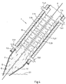
- the blow-suction device 6 comprises an upper part 6.1 and a lower part 6.2, with the upper part 6.1 extending across the entire width of the upper side of the belt (front side), while the lower part 6.2 extends across the entire width of the lower side of the belt (back side).
- the upper part 6.1 and the lower part 6.2 can each have a box-like design and are accordingly referred to as a blower/suction box or blower/suction box.
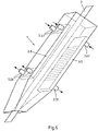
- the respective blowing and suction box (6.1, 6.2) is divided by partitions 7.3 into a branched blowing chamber 7.1' with blowing branches 7.10 running parallel to one another and a branched suction chamber 7.2' with suction branches 7.20 running parallel to one another.
- An injection branch 7.10 can be located directly next to a suction branch 7.20, in that both branches 7.10, 7.20 are separated from one another by the same partition wall 7.3.
- the subdivision into a branched blowing chamber 7.1' and a branched suction chamber 7.2' can be realized, for example, by a meandering or folded partition 7.3 or by meandering partitions that are joined together in a gas-tight manner at their abutting ends be as in figure 5 is sketched.
- connection piece 7.51 for suction of the protective gas is arranged below the connection piece 7.41, through which the protective gas is supplied (see also 6 ). This ensures that the flow of the inert gas that is blown in is always or essentially only directed downwards, as a result of which a flow of zinc vapor from the zinc bath into the nozzle 1 is effectively prevented.
- the lower main chamber section 7.5 of the blower/suction box 6.1 or 6.2 preferably has at least two connection pieces 7.51 for sucking off inert gas loaded with zinc vapor is provided.
- the connecting pieces 7.41 of the upper main chamber section 7.4 are arranged at a distance from one another transversely to the direction of travel of the belt.
- the connecting pieces 7.51 of the lower main chamber section 7.5 are spaced apart from one another transversely to the direction of travel of the belt.
- the injection and suction branches 7.10, 7.20 are provided with a large number of openings (nozzles) 7.11, 7.21, which serve as injection openings and suction openings, respectively.
- These openings (nozzles) 7.11, 7.21 are arranged or designed in such a way that the protective gas flowing out of the blow-in openings 7.11 is directed or hits the surface of the strip 2 facing the blow-in opening at an angle of incidence in the range of 70° to 110°, preferably 80° to 100°.
- the injection nozzles 7.11 are preferably designed in such a way that the protective gas flowing out of them is directed essentially at right angles to the surface of the strip (cf. 2 and 4 ).
- the distance between the respective injection nozzle 7.11 and at least one suction opening 7.21 assigned to it is selected in such a way that at a predetermined or specifiable flow rate of the injected protective gas, the entrainment of protective gas in the direction of the zinc bath 3 that occurs when the strip 2 is moving is effectively interrupted or at least minimized .
- the entrainment of protective gas caused by the strip movement contributes to a "natural gas movement".
- the natural gas movement is also driven by the usually existing temperature difference between the relatively hot protective gas entrained by the strip 2 above the zinc bath 3 and the colder protective gas in the upper area of the nozzle 1.
- the interruption or blocking of this natural gas movement according to the invention also means that it is carried along or the transport of zinc vapor from the zinc bath surface 3.1 to the upper nozzle area is interrupted or at least minimized.
- At least one suction opening 7.21 is located in the immediate vicinity of each injection opening 7.11.
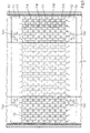
- the injection openings 7.11 and the suction openings 7.21 are arranged in a matrix. The blowing in and sucking off thus takes place in several stages, preferably in at least three stages.
- the injection openings 7.11 are arranged offset to the suction openings 7.21 in the direction of strip travel and across the strip width (cf. figure 5 ).
- the injection openings 7.11 and the suction openings 7.21 are preferably arranged at an equal distance from one another.
- a large amount of protective gas can be exchanged via the gas injection channels 7.10 without a large amount of gas being transported in the direction of strip travel.
- the band 2 is not excited to vibrate as a result.
- the undesired transport of zinc vapor from the immersion region of the strip 2 into the upper part of the snout 1 is not supported by the gas flow.
- the alternating arrangement of injection nozzles 7.11 and suction nozzles 7.21 ( 3 ) the nozzle cross-section can be completely flowed through in the transverse direction. Shielding gas not yet loaded with zinc dust mixes with shielding gas loaded with zinc dust and is extracted in close proximity.
- the blowing-suction device 6 or the blowing-suction box 6.1, 6.2 can also be designed in such a way that the injection openings 7.11 on prong-like branches 7.10 of a comb-shaped blowpipe structure 7.1 and the Suction openings 7.21 are formed on prong-like branches 7.20 of a comb-shaped suction tube structure 7.2, the prong-like branches 7.10 of the comb-shaped blower tube structure 7.1 and the prong-like branches 7.20 of the comb-shaped suction tube structure 7.2 interlocking.
- This configuration enables the distance between the injection openings 7.11 and the suction openings 7.21 to be adjusted by shifting the comb-shaped blowing tube structure 7.1 relative to the comb-shaped suction tube structure 7.2.
- a zinc separation device 10 for cleaning the protective gas loaded with zinc vapor and/or zinc dust is integrated in the return line 8.
- the zinc separating device 10 is preferably provided with a cooling device which effects a re-sublimation of zinc vapor.
- the resulting zinc dust can be separated from the protective gas by means of a separating device and fed into a collection container 10.1.
- the gradual blowing in of cleaned or unloaded inert gas and the extraction of inert gas laden with zinc vapor and/or zinc dust in the immediate vicinity of the injection points reduces the concentration of zinc vapor and/or zinc dust in the inert gas in nozzle 1 and thus the partial pressure of the zinc vapor gradually down to an uncritical level.
- the gradual reduction of the content of zinc vapor and zinc dust in the protective gas laden with it is in 4 schematically sketched, with the serpentine arrows Z for zinc vapor, the straight arrows G indicate the flow direction of the protective gas in the trunk 1 and in the blowing suction device (blasting suction box) and the "point clouds" D represent zinc dust. It is to see that the content of zinc vapor and zinc dust gradually decreases from the zinc bath surface 3.1 in the direction of the annealing furnace.
- the cleaned inert gas stream is heated by means of a gas heater 11, for example to a temperature in the range from 450 to 600.degree.
- the snout 1 with the blowing and suction device or the blowing and suction boxes 6.1, 6.2 is heated by this gas flow in such a way that at no point in the snout 1 does the dew point or resublimation temperature of zinc vapor fall below.
- the gas injection channels 7.10 run along the longitudinal axis of the strip or longitudinal axis of the nozzle and parallel to the suction lines 7.20 arranged between them. In combination with the suction lines 7.20, the gas injection channels 7.10 cover a longitudinal section of the strip 2 completely or essentially completely both on the underside of the strip and on the upper side of the strip. This causes a uniform surface temperature of the blower/suction device or blower/suction boxes 6.1, 6.2, the surface temperature being above the dew point or resublimation temperature of zinc vapor.
- the device 6 is designed as a push-pull system. Hot protective gas is blown into the nozzle 1 at a slight overpressure via the injection openings 7.11 in order to generate cross-flows at the injection openings 7.11 (outlet points).
- the flow of inert gas blown in is adjusted to be equal to or slightly below the amount of gas flow extracted by means of a measuring and control device. For example, per hinge side (blow-suction box 6.1 or 6.2) the inert gas flow blown in is about 150 Nm 3 /h at approx. 600°C, while the inert gas flow extracted per strip side including zinc vapor is approx. 200 Nm 3 /h.
- the main blowing chamber (main blowing line) 7.1 and the injection branches (gas injection channels) 7.10 and preferably also the main suction chamber 7.2 and the suction branches (suction lines) 7.20 are thermally insulated from the trunk construction by a heat insulating layer.
- the snout 1 is also provided with an outer thermal insulation 12 in order to keep the inside of the snout walls at a temperature greater than 300°C.
- the lowermost part of the snout 1, i.e. the snout end piece 1.1 located between the blowing suction device and the zinc bath 3, is preferably provided with thermal insulation 13.
- the thermal insulation 13 ensures that the walls or wall sections of the trunk provided with it are warmer than the dew point or resublimation temperature of the protective gas-zinc vapor mixture during operation of the galvanizing plant.
- the thermal insulation 13 is formed, for example, from mineral wool and/or ceramic plates and surrounds the trunk end piece 1.1, preferably in the form of a jacket.
- a further embodiment of the invention provides that the snout end piece 1.1 is provided with a heating device (not shown) in addition to or as an alternative to the heat insulation 13.
- the furnace nozzle 1 designed according to the invention can be divided into three areas A, B and C with regard to the protective gas (cf. 1 ).
- the area A includes the end piece 1.1, which is preferably provided with thermal insulation 13. In this area A there is a relatively high zinc vapor load with little gas movement.
- the surface temperature of the trunk 1 is above 440° C. in this area.
- Area A is followed by area B, which is equipped with the blowing and suction device according to the invention (e.g. in the form of blowing and suction boxes 6.1, 6.2).
- Area B serves as a separation lock or gas curtain. It interrupts the "natural gas flow", in particular the entrainment of protective gas caused by the strip movement in the direction of the zinc bath 3, by blowing in cleaned hot protective gas while at the same time sucking off gas laden with zinc vapor in close proximity to the injection points 7.11. Due to the multi-stage arrangement of the injection nozzles 7.11 and suction nozzles 7.21, the concentration of zinc vapor is gradually reduced in area B.
- the surface temperatures of the blow and suction boxes 6.1, 6.2 and the insides of the trunk 1 are above the dew point or resublimation temperature of zinc vapor, i.e. above 400°C.
- Area C follows above area B.
- Area C is characterized by a low zinc vapor content in the protective gas.
- the surface temperature of the inside of the nozzle is more than 300°C in area C, which prevents condensation or resublimation of the zinc vapor that is still present in the protective gas to a small extent.
- the implementation of the invention is not limited to the exemplary embodiments described above. Rather, numerous variants are possible, which also make use of the invention specified in the attached patent claims in the case of designs that deviate from the exemplary embodiments illustrated in the drawing.
- the mutually parallel injection branches 7.10 and suction branches 7.20 of the blowing suction box 6.1, 6.2 or the "tines" of the comb-shaped blowing tube structure 7.1 and the comb-shaped suction tube structure 7.2 can also be aligned transversely to the direction of belt travel. Which of these variants is implemented depends on the course of the main lines for the protective gas supply and suction in relation to the orientation of the trunk 1 and the relevant mounting options.
Landscapes
- Chemical & Material Sciences (AREA)
- Engineering & Computer Science (AREA)
- Materials Engineering (AREA)
- Mechanical Engineering (AREA)
- Metallurgy (AREA)
- Organic Chemistry (AREA)
- Chemical Kinetics & Catalysis (AREA)
- Physics & Mathematics (AREA)
- Thermal Sciences (AREA)
- Crystallography & Structural Chemistry (AREA)
- Coating With Molten Metal (AREA)
- Heat Treatment Of Strip Materials And Filament Materials (AREA)
Claims (16)
- Procédé servant à éviter les défauts de surface dus à la poussière de zinc sur une bande métallique galvanisée dans une installation de galvanisation de bandes en continu, selon lequel une bande métallique (2) chauffée dans un four de recuit à passage est déplacée sous gaz protecteur par une buse de four (1) et immergée dans un bain de zinc (3), selon lequel le côté supérieur et le côté inférieur de la bande métallique (2) sont exposés au gaz protecteur par des ouvertures d'injection (7.11) dans la buse de four (1), et selon lequel le gaz protecteur chargé avec de la vapeur de zinc et/ou de la poussière de zinc est aspiré par des ouvertures d'aspiration (7.21), qui sont agencées des deux côtés de la bande métallique (2) à côté des ouvertures d'injection (7.11), caractérisé en ce qu'une pluralité des ouvertures d'injection (7.11) sont configurées et agencées dans la buse de four (1) de sorte que le gaz protecteur qui s'écoule de ces ouvertures d'injection (7.11) soit orienté à un angle d'impact dans la plage allant de 70° à 110°, de préférence de 80° à 100°, sur la surface de la bande métallique (2) opposée à l'ouverture d'injection (7.11) respective, la distance entre l'ouverture d'injection (7.11) respective de la pluralité des ouvertures d'injection (7.11) et au moins une ouverture d'aspiration (7.21) attribuée à celle-ci parmi la pluralité d'ouvertures d'aspiration (7.21) étant choisie et la vitesse d'écoulement du gaz protecteur sortant de l'ouverture d'injection (7.11) respective étant ajustée de sorte qu'un entraînement de gaz protecteur dans la direction du bain de zinc (3) qui a lieu lors du mouvement de la bande métallique (2) soit contré, la distance entre l'ouverture d'injection (7.11) respectif et l'au moins une ouverture d'aspiration (7.21) qui lui est affecté étant inférieur ou égal à 25 cm.
- Procédé selon la revendication 1, caractérisé en ce que le gaz protecteur introduit par les ouvertures d'injection (7.11) est porté auparavant à une température d'au moins 500 °C, de préférence d'au moins 550 °C.
- Procédé selon la revendication 1 ou 2, caractérisé en ce que l'injection de gaz protecteur par les ouvertures d'injection (7.11) et l'aspiration de gaz protecteur par les ouvertures d'aspiration (7.21) sont réalisées en au moins trois étapes, qui sont agencées les unes après les autres dans la direction de déplacement de la bande, chacune des étapes étant constituée par une série d'au moins cinq, de préférence d'au moins sept ouvertures d'injection (7.11) et une série d'au moins cinq, de préférence d'au moins sept, ouvertures d'aspiration (7.21).
- Procédé selon l'une quelconque des revendications 1 à 3, caractérisé en ce que la buse de four (1) est portée à une température d'au moins 400 °C au moins dans une zone qui s'étend depuis le bain de zinc (3) jusqu'aux ouvertures d'injection (7.11) et/ou aux ouvertures d'aspiration (7.21).
- Procédé selon l'une quelconque des revendications 1 à 4, caractérisé en ce que le débit volumique de gaz protecteur introduit par les ouvertures d'injection (7.11) est ajusté identique au débit volumique de gaz protecteur aspiré par les ouvertures d'aspiration (7.21) ou est ajusté à une valeur située au plus 5 % en dessous du débit volumique de gaz protecteur aspiré.
- Procédé selon l'une quelconque des revendications 1 à 5, caractérisé en ce que le gaz protecteur aspiré, chargé avec de la vapeur de zinc et/ou de la poussière de zinc, est purifié au moyen d'un dispositif de séparation de zinc (10).
- Dispositif servant à éviter les défauts de surface dus à la poussière de zinc sur une bande métallique galvanisée dans une installation de galvanisation de bandes en continu, dans lequel une bande métallique (2) chauffée dans un four de recuit à passage à galvaniser est déplacée sous gaz protecteur par une buse de four (1) et immergée dans un bain de zinc (3), la buse de four (1) étant munie d'ouvertures d'injection (7.11) par lesquelles le côté supérieur et le côté inférieur de la bande métallique (2) peuvent être exposés à un gaz protecteur, et des ouvertures d'aspiration (7.21) pour l'aspiration du gaz protecteur chargé avec de la vapeur de zinc et/ou de la poussière de zinc étant agencées à côté des ouvertures d'injection (7.11), caractérisé en ce qu'une pluralité des ouvertures d'injection (7.11) sont configurées et agencées dans la buse de four (1) de sorte que le gaz protecteur qui s'écoule de ces ouvertures d'injection (7.11) soit orienté à un angle d'impact dans la plage allant de 70° à 110°, de préférence de 80° à 100°, sur la surface de la bande métallique (2) opposée à l'ouverture d'injection (7.11) respective, la distance entre l'ouverture d'injection (7.11) respective de la pluralité des ouvertures d'injection (7.11) et au moins une ouverture d'aspiration (7.21) attribuée à celle-ci parmi la pluralité d'ouvertures d'aspiration (7.21) étant choisie de sorte qu'à une vitesse d'écoulement fixée ou pouvant être fixée du gaz protecteur sortant de l'ouverture d'injection (7.11) respective, un entraînement de gaz protecteur dans la direction du bain de zinc (3) qui a lieu lors du mouvement de la bande métallique (2) soit contré, la distance entre l'ouverture d'injection (7.11) respectif et l'au moins une ouverture d'aspiration (7.21) qui lui est affecté étant inférieur ou égal à 25 cm.
- Dispositif selon la revendication 7, caractérisé en ce que les ouvertures d'aspiration (7.21) sont raccordées aux ouvertures d'injection (7.11) par une conduite de recyclage (8) munie d'au moins un ventilateur d'aspiration (9), la conduite de recyclage (8) étant munie d'au moins un dispositif de chauffage (11) pour le chauffage du gaz protecteur à une température d'au moins 500 °C, de préférence d'au moins 550 °C.
- Dispositif selon la revendication 8, caractérisé en ce que la conduite de recyclage (8) est munie d'un dispositif de séparation du zinc (10).
- Dispositif selon les revendications 7 à 9, caractérisé en ce que les ouvertures d'injection (7.11) pour l'injection d'un gaz protecteur et les ouvertures d'aspiration (7.21) pour l'aspiration du gaz protecteur sont configurées en au moins trois étapes, qui sont agencées les unes après les autres dans la direction de déplacement de la bande, chacune des étapes étant constituée par une série d'au moins cinq, de préférence d'au moins sept ouvertures d'injection (7.11) et une série d'au moins cinq, de préférence d'au moins sept, ouvertures d'aspiration (7.21).
- Dispositif selon l'une quelconque des revendications 7 à 10, caractérisé en ce que les ouvertures d'injection (7.11) et les ouvertures d'aspiration (7.21) sont agencées en forme de matrice.
- Dispositif selon l'une quelconque des revendications 7 à 11, caractérisé en ce que les ouvertures d'injection (7.11) sont agencées dans la direction de déplacement de la bande et sur la largeur de la bande en décalage par rapport aux ouvertures d'aspiration (7.21).
- Dispositif selon l'une quelconque des revendications 7 à 12, caractérisé en ce que les ouvertures d'injection (7.11) et les ouvertures d'aspiration (7.21) sont agencées espacées les unes des autres de manière uniforme.
- Dispositif selon l'une quelconque des revendications 7 à 13, caractérisé en ce que les ouvertures d'injection (7.21) sont configurées sur des branches en forme de dents (7.10) d'une structure de tube d'injection en forme de peigne (7.1) et les ouvertures d'aspiration (7.21) sur des branches en forme de dents (7.20) d'une structure de tube d'aspiration en forme de peigne (7.2), les branches en forme de dents (7.10) de la structure de tube d'injection en forme de peigne (7.1) et les branches en forme de dents (7.20) de la structure de tube d'aspiration en forme de peigne (7.2) étant imbriquées.
- Dispositif selon la revendication 14, caractérisé en ce que la structure de tube d'injection en forme de peigne (7.1) et la structure de tube d'aspiration en forme de peigne (7.2) sont isolées thermiquement par un isolement thermique contre la buse de four (1).
- Dispositif selon l'une quelconque des revendications 7 à 15, caractérisé en ce que la buse de four (1) est muni d'un isolement thermique (13) et/ou d'un dispositif de chauffage au moins dans une zone (1.1, A) qui s'étend depuis le bain de zinc (3) jusqu'aux ouvertures d'injection (7.11) et/ou aux ouvertures d'aspiration (7.21).
Priority Applications (1)
| Application Number | Priority Date | Filing Date | Title |
|---|---|---|---|
| PL13735251T PL2870268T3 (pl) | 2012-07-06 | 2013-07-05 | Sposób i urządzenie do zapobiegania wadom powierzchni wywoływanym przez pył cynkowy podczas cynkowania taśm metodą ciągłą |
Applications Claiming Priority (2)
| Application Number | Priority Date | Filing Date | Title |
|---|---|---|---|
| DE102012106106.8A DE102012106106A1 (de) | 2012-07-06 | 2012-07-06 | Verfahren und Vorrichtung zur Vermeidung von durch Zinkstaub verursachten Oberflächenfehlern in einer kontinuierlichen Bandverzinkung |
| PCT/EP2013/064249 WO2014006183A1 (fr) | 2012-07-06 | 2013-07-05 | Procédé et dispositif servant à éviter les défauts de surface dus à la poussière de zinc dans une installation de galvanisation de feuillards en continu |
Publications (3)
| Publication Number | Publication Date |
|---|---|
| EP2870268A1 EP2870268A1 (fr) | 2015-05-13 |
| EP2870268B1 EP2870268B1 (fr) | 2016-09-07 |
| EP2870268B2 true EP2870268B2 (fr) | 2022-11-30 |
Family
ID=48782310
Family Applications (1)
| Application Number | Title | Priority Date | Filing Date |
|---|---|---|---|
| EP13735251.4A Not-in-force EP2870268B2 (fr) | 2012-07-06 | 2013-07-05 | Procédé et dispositif servant à éviter les défauts de surface dus à la poussière de zinc dans une installation de galvanisation de feuillards en continu |
Country Status (6)
| Country | Link |
|---|---|
| US (1) | US9695496B2 (fr) |
| EP (1) | EP2870268B2 (fr) |
| DE (1) | DE102012106106A1 (fr) |
| ES (1) | ES2605829T5 (fr) |
| PL (1) | PL2870268T3 (fr) |
| WO (1) | WO2014006183A1 (fr) |
Families Citing this family (12)
| Publication number | Priority date | Publication date | Assignee | Title |
|---|---|---|---|---|
| JP6256325B2 (ja) * | 2014-12-15 | 2018-01-10 | Jfeスチール株式会社 | 連続溶融亜鉛めっき方法及び連続溶融亜鉛めっき設備 |
| DE102015108334B3 (de) * | 2015-05-27 | 2016-11-24 | Thyssenkrupp Ag | Vorrichtung und Verfahren zur verbesserten Metalldampfabsaugung bei einem kontinuierlichen Schmelztauchverfahren |
| CN105063535A (zh) * | 2015-08-04 | 2015-11-18 | 江苏捷帝机器人股份有限公司 | 一种机械人关节轴镀锌装置 |
| BE1023837B1 (fr) * | 2016-01-29 | 2017-08-09 | Centre De Recherches Metallurgiques Asbl | Dispositif pour la stabilisation hydrodynamique d'une bande metallique en defilement continu |
| DE202017101798U1 (de) | 2017-03-28 | 2018-06-01 | Schuh Anlagentechnik Gmbh | Mischabscheider für heiße Gase sowie Verzinkungsanlage mit wenigstens einem solchen Mischabscheider |
| DE102017106678A1 (de) | 2017-03-28 | 2018-10-04 | Schuh Anlagentechnik Gmbh | Mischabscheider für heiße Gase sowie Verzinkungsanlage mit wenigstens einem solchen Mischabscheider |
| CN110832104B (zh) * | 2017-06-12 | 2021-11-23 | 蒂森克虏伯钢铁欧洲股份公司 | 用于气体气氛分离的装置和方法 |
| EP3638821B1 (fr) | 2017-06-12 | 2021-01-13 | ThyssenKrupp Steel Europe AG | Pièce en forme de trompe pour une installation de revêtement par galvanisation à chaud |
| CN110741104B (zh) | 2017-06-12 | 2021-06-11 | 蒂森克虏伯钢铁欧洲股份公司 | 用于热浸镀层设备的风口支管及其运行方法 |
| DE102018211182A1 (de) * | 2018-07-06 | 2020-01-09 | Thyssenkrupp Ag | Vorrichtung und Verfahren zum Schmelztauchbeschichten eines Metallbandes |
| CN110358999B (zh) * | 2019-08-15 | 2021-08-24 | 武汉钢铁有限公司 | 一种具有锌灰喷吹放散处理功能的热镀锌炉鼻子 |
| WO2024088875A1 (fr) * | 2022-10-25 | 2024-05-02 | Tata Steel Ijmuiden B.V. | Procédé pour fournir un gaz hnx dans une trompe dans un dispositif de revêtement par dépôt en bain fondu et une trompe |
Citations (2)
| Publication number | Priority date | Publication date | Assignee | Title |
|---|---|---|---|---|
| JPH07316760A (ja) † | 1994-05-30 | 1995-12-05 | Nisshin Steel Co Ltd | 連続溶融めっきにおけるスナウト内ドロス発生防止装置 |
| KR20030049330A (ko) † | 2001-12-14 | 2003-06-25 | 주식회사 포스코 | 소둔로 스나우트의 아연재 흡입 및 가스 분사장치 |
Family Cites Families (6)
| Publication number | Priority date | Publication date | Assignee | Title |
|---|---|---|---|---|
| JPH07157853A (ja) | 1993-12-06 | 1995-06-20 | Nippon Steel Corp | 溶融金属めっきのスナウト内亜鉛ヒューム除去方法及び装置 |
| JPH07157854A (ja) * | 1993-12-06 | 1995-06-20 | Nippon Steel Corp | 溶融金属めっきのスナウト内清浄化方法及び装置 |
| JPH09228016A (ja) | 1996-02-23 | 1997-09-02 | Kawasaki Steel Corp | 溶融金属めっき方法及びその装置 |
| JPH11302811A (ja) | 1998-04-17 | 1999-11-02 | Nippon Steel Corp | 連続亜鉛メッキ設備の炉内雰囲気ガス制御装置 |
| US6517955B1 (en) * | 1999-02-22 | 2003-02-11 | Nippon Steel Corporation | High strength galvanized steel plate excellent in adhesion of plated metal and formability in press working and high strength alloy galvanized steel plate and method for production thereof |
| EP1587966B1 (fr) * | 2003-01-15 | 2017-05-17 | Nippon Steel & Sumitomo Metal Corporation | Feuille d'acier galvanise a chaud presentant une resistance elevee et methode de production de cette feuille |
-
2012
- 2012-07-06 DE DE102012106106.8A patent/DE102012106106A1/de not_active Withdrawn
-
2013
- 2013-07-05 ES ES13735251T patent/ES2605829T5/es active Active
- 2013-07-05 WO PCT/EP2013/064249 patent/WO2014006183A1/fr not_active Ceased
- 2013-07-05 PL PL13735251T patent/PL2870268T3/pl unknown
- 2013-07-05 US US14/412,929 patent/US9695496B2/en not_active Expired - Fee Related
- 2013-07-05 EP EP13735251.4A patent/EP2870268B2/fr not_active Not-in-force
Patent Citations (2)
| Publication number | Priority date | Publication date | Assignee | Title |
|---|---|---|---|---|
| JPH07316760A (ja) † | 1994-05-30 | 1995-12-05 | Nisshin Steel Co Ltd | 連続溶融めっきにおけるスナウト内ドロス発生防止装置 |
| KR20030049330A (ko) † | 2001-12-14 | 2003-06-25 | 주식회사 포스코 | 소둔로 스나우트의 아연재 흡입 및 가스 분사장치 |
Also Published As
| Publication number | Publication date |
|---|---|
| ES2605829T3 (es) | 2017-03-16 |
| EP2870268B1 (fr) | 2016-09-07 |
| US9695496B2 (en) | 2017-07-04 |
| ES2605829T5 (es) | 2023-03-16 |
| US20150167138A1 (en) | 2015-06-18 |
| DE102012106106A1 (de) | 2014-09-18 |
| EP2870268A1 (fr) | 2015-05-13 |
| WO2014006183A1 (fr) | 2014-01-09 |
| PL2870268T3 (pl) | 2017-07-31 |
Similar Documents
| Publication | Publication Date | Title |
|---|---|---|
| EP2870268B2 (fr) | Procédé et dispositif servant à éviter les défauts de surface dus à la poussière de zinc dans une installation de galvanisation de feuillards en continu | |
| DE4336364C2 (de) | Vorrichtung zum Erhitzen oder zum Kühlen von tafelförmigem oder bandförmigem Behandlungsgut aus Glas oder keramischem Werkstoff | |
| EP3303650B1 (fr) | Dispositif et procédé pour une aspiration améliorée de vapeurs métalliques dans un procédé d'immersion à chaud continu | |
| DE60025269T2 (de) | Verfahren und vorrichtung zum erwärmen von glass | |
| DE3638426C2 (de) | Verfahren und Vorrichtung zur Ausbildung eines Metalloxidüberzuges auf einem heißen Glassubstrat | |
| DE69708482T2 (de) | Durchlaufglühverfahren von Metallband in verschiedenen Schutzgasen und Vorrichtung | |
| EP1390680B1 (fr) | Reacteur avec arret de gaz faisant intervenir des canalisations de gaz | |
| EP3632640B1 (fr) | Installation de traitement pour une bande de matière flexible pouvant être guidée vers un four de traitement, en particulier feuille en matière plastique | |
| DE102005033776B4 (de) | Flachglasofen | |
| AT396927B (de) | Vorrichtung und verfahren zum ausbilden eines überzuges auf einem glassubstrat | |
| AT396928B (de) | Verfahren und vorrichtung zum pyrolytischen überziehen von glas | |
| AT511034B1 (de) | Verfahren zum kontrollieren einer schutzgasatmosphäre in einer schutzgaskammer zur behandlung eines metallbandes | |
| DE2618168C3 (de) | Verfahren und Vorrichtung zur Herstellung von wärmereflektierendem Glas | |
| EP3638823B1 (fr) | Trompe pour une installation de revêtement par immersion à chaud ainsi que son procédé de fonctionnement | |
| DE60310106T2 (de) | Abkühlvorrichtung für stahlband | |
| DE10330196B4 (de) | Anlage zur Wärmebehandlung von Glas | |
| EP3638822B1 (fr) | Dispositif et procédé de séparation d'atmosphères de gaz | |
| DE102017111991B4 (de) | Vorrichtung zum Kühlen von heißen, planen Gegenständen | |
| EP3591088B1 (fr) | Dispositif de revêtement par immersion à chaud d'une bande métallique | |
| DE2852815C2 (fr) | ||
| AT526925B1 (de) | Temperiereinrichtung | |
| DE2043880A1 (de) | Verfahren zur Wärmebehandlung von auf der Oberflache mit z B Farbe, Lack od dgl behandelten Gegenstanden, insbesondere aus Holz, und Vorrichtung zur Durchfuhrung des Verfahrens | |
| DE102008028592B3 (de) | Abkühleinrichtung mit Dampfsperre für eine Durchlauf-Wärmebehandlungsanlage | |
| DE1729287C3 (de) | Vorrichtung zur Wärmebehandlung einer Warenbahn | |
| DE9104693U1 (de) | Ofen zum Erwärmen von Metallgut |
Legal Events
| Date | Code | Title | Description |
|---|---|---|---|
| PUAI | Public reference made under article 153(3) epc to a published international application that has entered the european phase |
Free format text: ORIGINAL CODE: 0009012 |
|
| 17P | Request for examination filed |
Effective date: 20141222 |
|
| AK | Designated contracting states |
Kind code of ref document: A1 Designated state(s): AL AT BE BG CH CY CZ DE DK EE ES FI FR GB GR HR HU IE IS IT LI LT LU LV MC MK MT NL NO PL PT RO RS SE SI SK SM TR |
|
| AX | Request for extension of the european patent |
Extension state: BA ME |
|
| DAX | Request for extension of the european patent (deleted) | ||
| GRAP | Despatch of communication of intention to grant a patent |
Free format text: ORIGINAL CODE: EPIDOSNIGR1 |
|
| RIC1 | Information provided on ipc code assigned before grant |
Ipc: C23C 2/40 20060101ALI20160129BHEP Ipc: C23C 2/00 20060101ALI20160129BHEP Ipc: C23C 2/06 20060101AFI20160129BHEP Ipc: C23C 2/02 20060101ALI20160129BHEP Ipc: C21D 1/26 20060101ALI20160129BHEP Ipc: C21D 9/52 20060101ALI20160129BHEP Ipc: C21D 9/56 20060101ALI20160129BHEP |
|
| INTG | Intention to grant announced |
Effective date: 20160222 |
|
| GRAS | Grant fee paid |
Free format text: ORIGINAL CODE: EPIDOSNIGR3 |
|
| GRAA | (expected) grant |
Free format text: ORIGINAL CODE: 0009210 |
|
| AK | Designated contracting states |
Kind code of ref document: B1 Designated state(s): AL AT BE BG CH CY CZ DE DK EE ES FI FR GB GR HR HU IE IS IT LI LT LU LV MC MK MT NL NO PL PT RO RS SE SI SK SM TR |
|
| REG | Reference to a national code |
Ref country code: GB Ref legal event code: FG4D Free format text: NOT ENGLISH |
|
| REG | Reference to a national code |
Ref country code: CH Ref legal event code: EP |
|
| REG | Reference to a national code |
Ref country code: IE Ref legal event code: FG4D Free format text: LANGUAGE OF EP DOCUMENT: GERMAN |
|
| REG | Reference to a national code |
Ref country code: AT Ref legal event code: REF Ref document number: 826941 Country of ref document: AT Kind code of ref document: T Effective date: 20161015 |
|
| REG | Reference to a national code |
Ref country code: DE Ref legal event code: R096 Ref document number: 502013004383 Country of ref document: DE |
|
| REG | Reference to a national code |
Ref country code: NL Ref legal event code: FP |
|
| REG | Reference to a national code |
Ref country code: LT Ref legal event code: MG4D |
|
| PG25 | Lapsed in a contracting state [announced via postgrant information from national office to epo] |
Ref country code: HR Free format text: LAPSE BECAUSE OF FAILURE TO SUBMIT A TRANSLATION OF THE DESCRIPTION OR TO PAY THE FEE WITHIN THE PRESCRIBED TIME-LIMIT Effective date: 20160907 Ref country code: RS Free format text: LAPSE BECAUSE OF FAILURE TO SUBMIT A TRANSLATION OF THE DESCRIPTION OR TO PAY THE FEE WITHIN THE PRESCRIBED TIME-LIMIT Effective date: 20160907 Ref country code: NO Free format text: LAPSE BECAUSE OF FAILURE TO SUBMIT A TRANSLATION OF THE DESCRIPTION OR TO PAY THE FEE WITHIN THE PRESCRIBED TIME-LIMIT Effective date: 20161207 Ref country code: LT Free format text: LAPSE BECAUSE OF FAILURE TO SUBMIT A TRANSLATION OF THE DESCRIPTION OR TO PAY THE FEE WITHIN THE PRESCRIBED TIME-LIMIT Effective date: 20160907 |
|
| PG25 | Lapsed in a contracting state [announced via postgrant information from national office to epo] |
Ref country code: GR Free format text: LAPSE BECAUSE OF FAILURE TO SUBMIT A TRANSLATION OF THE DESCRIPTION OR TO PAY THE FEE WITHIN THE PRESCRIBED TIME-LIMIT Effective date: 20161208 Ref country code: LV Free format text: LAPSE BECAUSE OF FAILURE TO SUBMIT A TRANSLATION OF THE DESCRIPTION OR TO PAY THE FEE WITHIN THE PRESCRIBED TIME-LIMIT Effective date: 20160907 Ref country code: SE Free format text: LAPSE BECAUSE OF FAILURE TO SUBMIT A TRANSLATION OF THE DESCRIPTION OR TO PAY THE FEE WITHIN THE PRESCRIBED TIME-LIMIT Effective date: 20160907 |
|
| REG | Reference to a national code |
Ref country code: ES Ref legal event code: FG2A Ref document number: 2605829 Country of ref document: ES Kind code of ref document: T3 Effective date: 20170316 |
|
| PG25 | Lapsed in a contracting state [announced via postgrant information from national office to epo] |
Ref country code: RO Free format text: LAPSE BECAUSE OF FAILURE TO SUBMIT A TRANSLATION OF THE DESCRIPTION OR TO PAY THE FEE WITHIN THE PRESCRIBED TIME-LIMIT Effective date: 20160907 Ref country code: EE Free format text: LAPSE BECAUSE OF FAILURE TO SUBMIT A TRANSLATION OF THE DESCRIPTION OR TO PAY THE FEE WITHIN THE PRESCRIBED TIME-LIMIT Effective date: 20160907 |
|
| PG25 | Lapsed in a contracting state [announced via postgrant information from national office to epo] |
Ref country code: BG Free format text: LAPSE BECAUSE OF FAILURE TO SUBMIT A TRANSLATION OF THE DESCRIPTION OR TO PAY THE FEE WITHIN THE PRESCRIBED TIME-LIMIT Effective date: 20161207 Ref country code: CZ Free format text: LAPSE BECAUSE OF FAILURE TO SUBMIT A TRANSLATION OF THE DESCRIPTION OR TO PAY THE FEE WITHIN THE PRESCRIBED TIME-LIMIT Effective date: 20160907 Ref country code: SM Free format text: LAPSE BECAUSE OF FAILURE TO SUBMIT A TRANSLATION OF THE DESCRIPTION OR TO PAY THE FEE WITHIN THE PRESCRIBED TIME-LIMIT Effective date: 20160907 Ref country code: PT Free format text: LAPSE BECAUSE OF FAILURE TO SUBMIT A TRANSLATION OF THE DESCRIPTION OR TO PAY THE FEE WITHIN THE PRESCRIBED TIME-LIMIT Effective date: 20170109 Ref country code: SK Free format text: LAPSE BECAUSE OF FAILURE TO SUBMIT A TRANSLATION OF THE DESCRIPTION OR TO PAY THE FEE WITHIN THE PRESCRIBED TIME-LIMIT Effective date: 20160907 Ref country code: IS Free format text: LAPSE BECAUSE OF FAILURE TO SUBMIT A TRANSLATION OF THE DESCRIPTION OR TO PAY THE FEE WITHIN THE PRESCRIBED TIME-LIMIT Effective date: 20170107 |
|
| REG | Reference to a national code |
Ref country code: DE Ref legal event code: R026 Ref document number: 502013004383 Country of ref document: DE |
|
| PLBI | Opposition filed |
Free format text: ORIGINAL CODE: 0009260 |
|
| 26 | Opposition filed |
Opponent name: ARCELORMITTAL Effective date: 20170602 |
|
| PLAX | Notice of opposition and request to file observation + time limit sent |
Free format text: ORIGINAL CODE: EPIDOSNOBS2 |
|
| REG | Reference to a national code |
Ref country code: FR Ref legal event code: PLFP Year of fee payment: 5 |
|
| PG25 | Lapsed in a contracting state [announced via postgrant information from national office to epo] |
Ref country code: DK Free format text: LAPSE BECAUSE OF FAILURE TO SUBMIT A TRANSLATION OF THE DESCRIPTION OR TO PAY THE FEE WITHIN THE PRESCRIBED TIME-LIMIT Effective date: 20160907 |
|
| PG25 | Lapsed in a contracting state [announced via postgrant information from national office to epo] |
Ref country code: SI Free format text: LAPSE BECAUSE OF FAILURE TO SUBMIT A TRANSLATION OF THE DESCRIPTION OR TO PAY THE FEE WITHIN THE PRESCRIBED TIME-LIMIT Effective date: 20160907 |
|
| PLBB | Reply of patent proprietor to notice(s) of opposition received |
Free format text: ORIGINAL CODE: EPIDOSNOBS3 |
|
| REG | Reference to a national code |
Ref country code: CH Ref legal event code: PL |
|
| REG | Reference to a national code |
Ref country code: IE Ref legal event code: MM4A |
|
| PG25 | Lapsed in a contracting state [announced via postgrant information from national office to epo] |
Ref country code: LI Free format text: LAPSE BECAUSE OF NON-PAYMENT OF DUE FEES Effective date: 20170731 Ref country code: CH Free format text: LAPSE BECAUSE OF NON-PAYMENT OF DUE FEES Effective date: 20170731 Ref country code: IE Free format text: LAPSE BECAUSE OF NON-PAYMENT OF DUE FEES Effective date: 20170705 |
|
| REG | Reference to a national code |
Ref country code: FR Ref legal event code: PLFP Year of fee payment: 6 |
|
| PG25 | Lapsed in a contracting state [announced via postgrant information from national office to epo] |
Ref country code: MT Free format text: LAPSE BECAUSE OF FAILURE TO SUBMIT A TRANSLATION OF THE DESCRIPTION OR TO PAY THE FEE WITHIN THE PRESCRIBED TIME-LIMIT Effective date: 20160907 |
|
| PG25 | Lapsed in a contracting state [announced via postgrant information from national office to epo] |
Ref country code: AL Free format text: LAPSE BECAUSE OF FAILURE TO SUBMIT A TRANSLATION OF THE DESCRIPTION OR TO PAY THE FEE WITHIN THE PRESCRIBED TIME-LIMIT Effective date: 20160907 |
|
| APBM | Appeal reference recorded |
Free format text: ORIGINAL CODE: EPIDOSNREFNO |
|
| APBP | Date of receipt of notice of appeal recorded |
Free format text: ORIGINAL CODE: EPIDOSNNOA2O |
|
| APAH | Appeal reference modified |
Free format text: ORIGINAL CODE: EPIDOSCREFNO |
|
| PG25 | Lapsed in a contracting state [announced via postgrant information from national office to epo] |
Ref country code: HU Free format text: LAPSE BECAUSE OF FAILURE TO SUBMIT A TRANSLATION OF THE DESCRIPTION OR TO PAY THE FEE WITHIN THE PRESCRIBED TIME-LIMIT; INVALID AB INITIO Effective date: 20130705 Ref country code: MC Free format text: LAPSE BECAUSE OF FAILURE TO SUBMIT A TRANSLATION OF THE DESCRIPTION OR TO PAY THE FEE WITHIN THE PRESCRIBED TIME-LIMIT Effective date: 20160907 |
|
| APBQ | Date of receipt of statement of grounds of appeal recorded |
Free format text: ORIGINAL CODE: EPIDOSNNOA3O |
|
| PG25 | Lapsed in a contracting state [announced via postgrant information from national office to epo] |
Ref country code: CY Free format text: LAPSE BECAUSE OF FAILURE TO SUBMIT A TRANSLATION OF THE DESCRIPTION OR TO PAY THE FEE WITHIN THE PRESCRIBED TIME-LIMIT Effective date: 20160907 |
|
| PG25 | Lapsed in a contracting state [announced via postgrant information from national office to epo] |
Ref country code: MK Free format text: LAPSE BECAUSE OF FAILURE TO SUBMIT A TRANSLATION OF THE DESCRIPTION OR TO PAY THE FEE WITHIN THE PRESCRIBED TIME-LIMIT Effective date: 20160907 |
|
| PGFP | Annual fee paid to national office [announced via postgrant information from national office to epo] |
Ref country code: PL Payment date: 20210628 Year of fee payment: 9 |
|
| PGFP | Annual fee paid to national office [announced via postgrant information from national office to epo] |
Ref country code: NL Payment date: 20210721 Year of fee payment: 9 |
|
| PGFP | Annual fee paid to national office [announced via postgrant information from national office to epo] |
Ref country code: IT Payment date: 20210727 Year of fee payment: 9 Ref country code: AT Payment date: 20210722 Year of fee payment: 9 Ref country code: FI Payment date: 20210722 Year of fee payment: 9 |
|
| PGFP | Annual fee paid to national office [announced via postgrant information from national office to epo] |
Ref country code: TR Payment date: 20210701 Year of fee payment: 9 Ref country code: GB Payment date: 20210722 Year of fee payment: 9 |
|
| APBU | Appeal procedure closed |
Free format text: ORIGINAL CODE: EPIDOSNNOA9O |
|
| PUAH | Patent maintained in amended form |
Free format text: ORIGINAL CODE: 0009272 |
|
| STAA | Information on the status of an ep patent application or granted ep patent |
Free format text: STATUS: PATENT MAINTAINED AS AMENDED |
|
| PGFP | Annual fee paid to national office [announced via postgrant information from national office to epo] |
Ref country code: LU Payment date: 20220720 Year of fee payment: 10 Ref country code: ES Payment date: 20220921 Year of fee payment: 10 Ref country code: DE Payment date: 20220620 Year of fee payment: 10 |
|
| 27A | Patent maintained in amended form |
Effective date: 20221130 |
|
| AK | Designated contracting states |
Kind code of ref document: B2 Designated state(s): AL AT BE BG CH CY CZ DE DK EE ES FI FR GB GR HR HU IE IS IT LI LT LU LV MC MK MT NL NO PL PT RO RS SE SI SK SM TR |
|
| PGFP | Annual fee paid to national office [announced via postgrant information from national office to epo] |
Ref country code: FR Payment date: 20220720 Year of fee payment: 10 Ref country code: BE Payment date: 20220720 Year of fee payment: 10 |
|
| REG | Reference to a national code |
Ref country code: DE Ref legal event code: R102 Ref document number: 502013004383 Country of ref document: DE |
|
| REG | Reference to a national code |
Ref country code: NL Ref legal event code: MM Effective date: 20220801 |
|
| REG | Reference to a national code |
Ref country code: AT Ref legal event code: MM01 Ref document number: 826941 Country of ref document: AT Kind code of ref document: T Effective date: 20220705 |
|
| REG | Reference to a national code |
Ref country code: ES Ref legal event code: DC2A Ref document number: 2605829 Country of ref document: ES Kind code of ref document: T5 Effective date: 20230316 |
|
| GBPC | Gb: european patent ceased through non-payment of renewal fee |
Effective date: 20220705 |
|
| PG25 | Lapsed in a contracting state [announced via postgrant information from national office to epo] |
Ref country code: FI Free format text: LAPSE BECAUSE OF NON-PAYMENT OF DUE FEES Effective date: 20220705 Ref country code: AT Free format text: LAPSE BECAUSE OF NON-PAYMENT OF DUE FEES Effective date: 20220705 |
|
| PG25 | Lapsed in a contracting state [announced via postgrant information from national office to epo] |
Ref country code: GB Free format text: LAPSE BECAUSE OF NON-PAYMENT OF DUE FEES Effective date: 20220705 |
|
| PG25 | Lapsed in a contracting state [announced via postgrant information from national office to epo] |
Ref country code: NL Free format text: LAPSE BECAUSE OF NON-PAYMENT OF DUE FEES Effective date: 20220801 |
|
| PG25 | Lapsed in a contracting state [announced via postgrant information from national office to epo] |
Ref country code: IT Free format text: LAPSE BECAUSE OF NON-PAYMENT OF DUE FEES Effective date: 20220705 |
|
| REG | Reference to a national code |
Ref country code: DE Ref legal event code: R119 Ref document number: 502013004383 Country of ref document: DE |
|
| REG | Reference to a national code |
Ref country code: BE Ref legal event code: MM Effective date: 20230731 |
|
| PG25 | Lapsed in a contracting state [announced via postgrant information from national office to epo] |
Ref country code: LU Free format text: LAPSE BECAUSE OF NON-PAYMENT OF DUE FEES Effective date: 20230705 |
|
| PG25 | Lapsed in a contracting state [announced via postgrant information from national office to epo] |
Ref country code: LU Free format text: LAPSE BECAUSE OF NON-PAYMENT OF DUE FEES Effective date: 20230705 |
|
| PG25 | Lapsed in a contracting state [announced via postgrant information from national office to epo] |
Ref country code: DE Free format text: LAPSE BECAUSE OF NON-PAYMENT OF DUE FEES Effective date: 20240201 |
|
| PG25 | Lapsed in a contracting state [announced via postgrant information from national office to epo] |
Ref country code: FR Free format text: LAPSE BECAUSE OF NON-PAYMENT OF DUE FEES Effective date: 20230731 Ref country code: BE Free format text: LAPSE BECAUSE OF NON-PAYMENT OF DUE FEES Effective date: 20230731 |
|
| REG | Reference to a national code |
Ref country code: ES Ref legal event code: FD2A Effective date: 20240828 |
|
| PG25 | Lapsed in a contracting state [announced via postgrant information from national office to epo] |
Ref country code: TR Free format text: LAPSE BECAUSE OF NON-PAYMENT OF DUE FEES Effective date: 20220705 |
|
| PG25 | Lapsed in a contracting state [announced via postgrant information from national office to epo] |
Ref country code: ES Free format text: LAPSE BECAUSE OF NON-PAYMENT OF DUE FEES Effective date: 20230706 |
|
| PG25 | Lapsed in a contracting state [announced via postgrant information from national office to epo] |
Ref country code: ES Free format text: LAPSE BECAUSE OF NON-PAYMENT OF DUE FEES Effective date: 20230706 |
|
| PG25 | Lapsed in a contracting state [announced via postgrant information from national office to epo] |
Ref country code: PL Free format text: LAPSE BECAUSE OF NON-PAYMENT OF DUE FEES Effective date: 20220705 |
|
| PG25 | Lapsed in a contracting state [announced via postgrant information from national office to epo] |
Ref country code: PL Free format text: LAPSE BECAUSE OF NON-PAYMENT OF DUE FEES Effective date: 20220705 |