EP2871121B1 - Véhicule de type à selle - Google Patents
Véhicule de type à selle Download PDFInfo
- Publication number
- EP2871121B1 EP2871121B1 EP14182251.0A EP14182251A EP2871121B1 EP 2871121 B1 EP2871121 B1 EP 2871121B1 EP 14182251 A EP14182251 A EP 14182251A EP 2871121 B1 EP2871121 B1 EP 2871121B1
- Authority
- EP
- European Patent Office
- Prior art keywords
- fuel
- riding type
- type vehicle
- saddle riding
- seat
- Prior art date
- Legal status (The legal status is an assumption and is not a legal conclusion. Google has not performed a legal analysis and makes no representation as to the accuracy of the status listed.)
- Active
Links
Images




Classifications
-
- B—PERFORMING OPERATIONS; TRANSPORTING
- B62—LAND VEHICLES FOR TRAVELLING OTHERWISE THAN ON RAILS
- B62J—CYCLE SADDLES OR SEATS; AUXILIARY DEVICES OR ACCESSORIES SPECIALLY ADAPTED TO CYCLES AND NOT OTHERWISE PROVIDED FOR, e.g. ARTICLE CARRIERS OR CYCLE PROTECTORS
- B62J35/00—Fuel tanks specially adapted for motorcycles or engine-assisted cycles; Arrangements thereof
-
- B—PERFORMING OPERATIONS; TRANSPORTING
- B62—LAND VEHICLES FOR TRAVELLING OTHERWISE THAN ON RAILS
- B62J—CYCLE SADDLES OR SEATS; AUXILIARY DEVICES OR ACCESSORIES SPECIALLY ADAPTED TO CYCLES AND NOT OTHERWISE PROVIDED FOR, e.g. ARTICLE CARRIERS OR CYCLE PROTECTORS
- B62J17/00—Weather guards for riders; Fairings or stream-lining parts not otherwise provided for
- B62J17/02—Weather guards for riders; Fairings or stream-lining parts not otherwise provided for shielding only the rider's front
- B62J17/06—Leg guards
-
- B—PERFORMING OPERATIONS; TRANSPORTING
- B62—LAND VEHICLES FOR TRAVELLING OTHERWISE THAN ON RAILS
- B62K—CYCLES; CYCLE FRAMES; CYCLE STEERING DEVICES; RIDER-OPERATED TERMINAL CONTROLS SPECIALLY ADAPTED FOR CYCLES; CYCLE AXLE SUSPENSIONS; CYCLE SIDECARS, FORECARS, OR THE LIKE
- B62K2202/00—Motorised scooters
Definitions
- the present invention relates to a saddle riding type vehicle according to the preamble of independent claim 1.
- a saddle riding type vehicle can be taken from the prior art document JP S62-83282 A .
- a saddle riding type vehicle is provided with a fuel tank.
- a fuel tank is provided ahead of and below a seat and covered with a vehicle body cover from above.
- prior art document JP H03-21578 A discloses a saddle riding type vehicle with handles and a vehicle body cover having a front cover portion provided below the handles to store a steering shaft and a head pipe portion.
- a seat is provided behind the handles, wherein a distance between rear ends of the handles and a front end of the seat in the front-back direction is much larger than a distance between an upper end of a rear edge of the front cover portion and the rear ends of the handles in the front-back direction in a side view.
- a portion of the vehicle body cover is provided to extend in a front-back direction between the front cover portion and the seat and cover a fuel tank from above.
- a foot board portion is provided to each of left and right of the portion and connected to a lower end of the portion.
- the portion is provided with an arc shaped front section having an upper edge inclined backward and downward and a straight shaped rear section having an upper edge inclined backward and upward in a side view.
- the fuel tank is provided with a fuel inlet and a fuel cap used to cover the fuel inlet, wherein the fuel cap is being exposed at an upper surface of the straight shaped rear section of the cover portion.
- a straddling portion is provided in a relatively low position between handles and a seat.
- the straddling portion is provided with a center tunnel portion that extends in a front-back direction and has a rear part inclined obliquely downward.
- the center tunnel portion has an upwardly raised shape in a front cross section and stores a fuel tank therein.
- the center tunnel portion is provided with a lid and a tray opened/closed by the lid. A fuel inlet and a fuel cap of the fuel tank are provided in the tray of the center tunnel portion. When the lid of the center tunnel portion is opened and the fuel cap of the fuel tank is removed, the fuel inlet of the fuel tank is exposed.
- a distance between rear ends of the handles and a front end of the seat in the front-back direction is smaller than a distance between an upper end of a rear edge of a front cover portion that stores a steering mechanism and the rear ends of the handles in the front-back direction in a side view. Therefore, the scooter type vehicle has a compact vehicle body having a short wheelbase.
- the fuel tank is provided in the center tunnel portion positioned ahead of the seat and therefore a wide storage space is provided under the seat.
- a battery storage box and an item storage box are provided in the storage space.
- the scooter type vehicle described above can secure a fuel tank capacity and a storage space by arranging the fuel tank and these storage boxes in the described manner.
- the scooter type vehicle disclosed by JP-A 2012-62055 allows the fuel tank capacity and the storage space to be secured while keeping its body compact and therefore the center tunnel portion at the straddling portion is relatively high. Therefore, in the above described scooter type vehicle, a rider may feel inconvenience in straddling the straddling portion, which degrades comfort in getting on and off from the vehicle.
- a saddle riding type vehicle includes handles, a steering shaft that extends downward from the handles, a head pipe having the steering shaft inserted therein, a seat provided behind the handles, a storage space provided under the seat, a fuel tank having a fuel inlet and a fuel cap used to cover the fuel inlet, and a vehicle body cover.
- the vehicle body cover includes a front cover portion provided below the handles to store at least a part of the steering shaft and the head pipe, an arch portion provided to extend in a front-back direction between the front cover portion and the seat and cover the fuel tank from above and having a convex front sectional shape, and a foot board portion provided to each of left and right of the arch portion and connected to a lower end of the arch portion.
- the front cover portion has a rear edge that extends in an up-down direction in a side view.
- a distance between rear ends of the handles and a front end of the seat in the front-back direction is smaller than a distance between an upper end of the rear edge of the front cover portion and the rear ends of the handles in the front-back direction in the side view.
- the arch portion has a front part having an upper edge inclined backward and downward and a rear part having an upper edge inclined backward and upward in the side view.
- the fuel cap is exposed at an upper surface of the rear part of the arch portion.
- the saddle riding type vehicle described above has a compact vehicle body in which the distance between the rear ends of the handles and the front end of the seat in the front-back direction is smaller than the distance between the upper end of the rear edge of the front cover portion and the rear ends of the handles in the front-back direction in a side view.
- the saddle riding type vehicle described above has the compact vehicle body and can secure a sufficient capacity for the fuel tank and a sufficient storage space and provide increased comfort in getting on and off from the vehicle.
- a saddle riding type vehicle in which an arch portion having an upward raised front section is formed between a front cover portion and a seat, a fuel tank is provided in the arch portion, and a storage space is secured under the seat.
- the fuel tank and the storage space are provided in the arch portion and under the seat, respectively, so that the vehicle body can be compact in the front-back direction while a sufficient capacity for the fuel tank and a sufficient storage space are secured.
- a part of a vehicle body cover between the front cover portion that stores a steering mechanism and the seat usually has an increased height. Therefore, a rider may feel inconvenience in straddling a part of the vehicle body cover between the handles and the seat, which degrades comfort in getting on and off from the vehicle.
- a front part of the arch portion has its upper edge inclined backward and downward from a lower end of a rear edge of the front cover portion in a side view.
- a rear part of the arch portion has its upper edge inclined forward and downward from a front end part of the seat in a side view.
- the front end part of the seat is positioned below the lower end of the rear edge of the front cover portion.
- the arch portion having the above-described structure the low level part is extended as the rear part is prolonged in the front-back direction and the height of the arch portion as a whole is reduced.
- the inventor took notice of the point and had the fuel cap of the fuel tank exposed at an upper surface of the rear part of the arch portion so that the rear part of the arch portion had a greater length in the front-back direction than in a conventional saddle riding type vehicle. In this way, the height of the arch portion as a whole can be kept from increasing, and increased comfort in getting on and off from the vehicle can be provided.
- a fuel cap C1 of a fuel tank is exposed at an upper surface of a rear part B1 of an arch portion A1, so that a sufficient length L1 is secured for the rear part B1 of the arch portion A1 in the front-back direction.
- a rear part B2 of an arch portion A2 has a shorter length L2 in the front-back direction than the length L1 in the vehicle V1.
- a storage space should be secured under the arch portion A2. Therefore, a person skilled in the art would not set a lower end BE of an upper edge of the arch portion A2 in a side view to a lower position than that shown in Fig. 8B .
- the position of a front end FE of the upper edge of the arch portion A2 in a side view depends on the shape of the vehicle body frame and therefore the position of the front end FE would not be changed from the position shown in Fig. 8B .
- the rear part B1 has a greater length, so that the position of a front part F1 is lower, while in the vehicle V2, the rear part B2 has a shorter length and therefore a front part F2 has a greater height. More specifically, the height of the arch portion as a whole is lower in the vehicle V1 than in the vehicle V2. In this way, in the vehicle V1, the height of the arch portion A1 is kept from increasing, which provides increased comfort in getting on and off from the vehicle.
- a fuel cap of a fuel tank is exposed at an upper surface of a rear part of an arch portion, so that a lid used to cover the fuel cap is not necessary. Therefore, the arch portion can be further kept from increasing in height, which provides more comfort in getting on and off from the vehicle.
- the saddle riding type vehicle conceived by the inventor can provide increased comfort in getting on and off from the vehicle despite its compact vehicle body.
- front-back, left-right, and up-down directions refer to these directions as viewed from a rider on a saddle riding type vehicle.
- the arrow F indicates a forward direction and the arrow B indicates a backward direction.
- the arrow R indicates a rightward direction and the arrow L indicates a leftward direction.
- the arrow U indicates an upward direction and the arrow D indicates a downward direction.
- the same or corresponding portions are designated by the same reference characters and their description will not be repeated.
- Fig. 1 is a left side view of a saddle riding type vehicle 1 according to the embodiment.
- the saddle riding type vehicle 1 is a scooter type vehicle that includes a vehicle main body 10, a front wheel 20 provided at a front part of the vehicle main body 10, and a rear wheel 30 provided at a rear part of the vehicle main body 10.
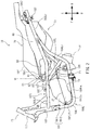
- Fig. 2 is a left side view of a part of the vehicle main body 10 removed of the vehicle body cover 17.
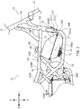
- Fig. 3 is a right side view of a part of the vehicle main body 10 removed of the vehicle body cover 17.
- the vehicle main body 10 includes left and right handles 11, a steering shaft 12, a front fork 13, a power unit 14, rear suspensions 15, a seat 16, and a vehicle body cover 17. As shown in Figs. 2 and 3 , the vehicle main body 10 further includes a vehicle body frame 18 and a fuel tank 19.
- the steering shaft 12 extends downward from the handles 11.
- the front fork 13 is connected to a lower part of the steering shaft 12 through a bracket which is not shown.
- a lower end part of the front fork 13 supports the front wheel 20 in a rotatable manner. As the handles 11 are operated, the direction of the front wheel 20 changes.
- the power unit 14 is provided below the seat 16 and swings in the up-down direction.
- the power unit 14 includes an engine and a transmission case provided behind the engine to store a transmission, though not specifically shown.
- the transmission case supports the rear wheel 30 in a rotatable manner.
- the engine is supported by the vehicle body frame 18.
- the rear suspensions 15 are provided on the right and left of the rear wheel 30 at the rear part of the vehicle main body 10. An upper end part of each of the rear suspensions 15 is supported by the vehicle body frame 18. The rear suspensions 15 each has a lower end part coupled to a rear end part of the power unit 14.
- the seat 16 is provided behind the handles 11.
- a front part 16f of the seat 16 has an upper edge that extends backward and obliquely upward in a side view.
- the hinge 40 includes a support member 41 and a movable member 42.
- the support member 41 is supported by the vehicle body frame 18.
- the support member 41 includes a rotation shaft P1.
- the movable member 42 has its front end part supported by the support member 41 so that the movable member 42 rotates around the rotation shaft P1 in the up-down direction.
- the movable member 42 has its rear end part attached to the front part 16f of the seat 16. The seat 16 rotates in the up-down direction as the movable member 42 rotates.
- a part of the hinge 40 is provided ahead of a front end E1 of the seat 16.
- a vertical line VL passing through a center of the rotation shaft P1 is substantially in the same position as the front end E1 of the seat 16 in the front-back direction. In this way, the part of the hinge 40 ahead of the vertical line VL is provided ahead of the front end E1 of the seat 16.
- a storage space S1 is provided under the seat 16.
- a battery storage box 50 that stores a battery and an item storage box 60 that stores an item such as a helmet are provided in the storage space S1.
- the battery storage box 50 is positioned behind the hinge 40 and substantially immediately under the front part 16f of the seat 16 in the storage space S1.
- the battery storage box 50 is supported by the vehicle body frame 18.
- the item storage box 60 is provided behind the battery storage box 50.
- a front end part of the item storage box 60 is supported by the battery storage box 50.
- a rear end part of the item storage box 60 is supported by the vehicle body frame 18.
- the item storage box 60 has a concave shape so that an item can be stored therein.
- Fig. 2 shows the state in which the battery storage box 50 and the item storage box 60 are covered with the seat 16. When the seat 16 is rotated upward, the battery storage box 50 and the item storage box 60 are exposed.
- the vehicle body frame 18 includes a head pipe portion 181, a front frame 182, an upper left frame 183L, a lower left frame 184L, and a left reinforcement frame 185L.
- the vehicle body frame 18 further includes an upper right frame 183R, a lower right frame 184R, and a right reinforcement frame 185R.
- the upper left frame 183L, the lower left frame 184L, and the left reinforcement frame 185L will generically be referred to as “left frames” and the upper right frame 183R, the lower right frame 184R, and the right reinforcement frame 185R will generically be referred to as "right frames” in some cases.
- the head pipe portion 181 is provided at a front part of the vehicle main body 10.
- the head pipe portion 181 has the steering shaft 12 inserted therein.
- the front frame 182 extends downward from the head pipe portion 181.
- the right frames have substantially the same structure as those of the left frames, and therefore the elements of the right frames corresponding to those of the left frames will be designated by similar reference characters and will not be described in detail. Note that as for reference characters for the right frames, "L" for the left frames is replaced by "R.” Note that the left and right frames may be symmetric or asymmetric with respect to a vertical plane through a vehicle center in a vehicle-widthwise direction.
- the upper left frame 183L extends backward and obliquely upward from the front frame 182.
- a part of the upper frame 183L is provided in an arch portion 174 of the vehicle body cover 17 that will be described.
- a front part 183Lf of the upper left frame 183L extends outward in the vehicle-widthwise direction from the front frame 182.
- a rear part 183Lr of the upper left frame 183L extends backward from a rear end of the front part 183Lf.
- a rear suspension support 187 is provided at a rear end part of the rear part 183Lr of the upper left frame 183L.
- the rear suspension support 187 supports an upper end part of a rear suspension 15 ( Fig. 1 ) provided to the left of the rear wheel 30.
- An upper end part of the rear suspension 15 provided to the right of the rear wheel 30 is supported by a rear suspension support (not shown) provided at a rear end part of a rear part 183Rr ( Fig. 3 ) of the upper right frame
- the lower left frame 184L is provided below the upper left frame 183L.
- the lower left frame 184L includes a front part 184Lf that extends downward and outward in the vehicle-widthwise direction from the front frame 182, an intermediate part 184Lm that extends backward from a lower end of the front part 184Lf, and a rear part 184Lr that extends backward and upward from a rear end of the intermediate part 184Lm.
- the rear part 184Lr is attached to the upper left frame 183L.
- the left reinforcement frame 185L is provided in front of a rear end of the rear part 184Lr of the lower left frame 184L.
- the left reinforcement frame 185L has an upper end connected to the upper left frame 183L and a lower end connected to the lower left frame 184L.
- the front part 184Lf of the lower left frame 184L, the left reinforcement frame 185L, the front part 184Rf of the lower right frame 184R, and the right reinforcement frame 185R are each provided with a fuel tank support 186 that supports the fuel tank 19.
- the vehicle body frame 18 is provided with bridges 1881 and 1882 that couple the upper left frame 183L and the upper right frame 183R.
- the bridge 1881 supports the hinge 40.
- the fuel tank 19 is provided in front of the seat 16.
- the fuel tank 19 includes a tank main body 191, a filler portion 192, and a fuel cap 193.
- the tank main body 191 is provided below the upper left frame 183L and the upper right frame 183R and above the lower left frame 184L and the lower right frame 184R.
- the tank main body 191 is provided as it is inclined forward. Note that "the tank 191 being inclined forward” refers to the state in which a joint J1 between an upper half body 1911 and a lower half body 1912 (that will be described) is inclined backward and upward in a side view.
- the tank main body 191 is supported by the four fuel tank supports 186 of the vehicle body frame 18.
- the tank main body 191 is supported by the two fuel tank supports 186 on the left and right provided at the upper left frame 183L and the upper right frame 183R and the two fuel tank supports 186 on the left and right provided at the left reinforcement frame 185L and the right reinforcement frame 185R.
- the tank main body 191 is protected against irregularities, obstacles, jumping stones, and the like on a road surface by the upper left frame 184L and the lower right frame 184R positioned below the tank main body 191.
- the inlet of a pump main body 71 (that will be described) is provided at front and lower parts of the tank main body 191.
- the arrangement of the inlet of the pump main body 71 allows fuel in the tank main body 191 to be fully used because the tank main body 191 is inclined forward.
- the tank main body 191 includes the upper half body 1911 in a convex shape and the lower half body 1912 in a concave shape.
- a lower end circumferential edge of the upper half body 1911 is connected to an upper end circumferential edge of the lower half body 1912.
- a flange that is not shown is formed along the entire periphery of the lower end of the upper half body 1911.
- a flange that is not shown is formed along the entire periphery of the upper end part of the lower half body 1912.
- the flange for the upper half body 1911 and the flange for the lower half body 1912 are joined by welding.
- the joint J1 between the flange for the upper half body 1911 and the flange for the lower half body 1912 are inclined backward and upward in a side view.
- a part of the flange for the lower half body 1912 positioned at a rear surface of the lower half body 1219 preferably has its rear edge bent upward. In this way, the flange for the lower half body 1912 becomes less bendable, which improves the strength of the tank main body 191.
- a lower surface of the lower half body 1912 includes a projection 1912a that projects downward.
- the projection 1912a is provided at a front part of the lower half body 1912.
- the projection 1912a is provided from a left end to a right end of the lower half body 1912.
- a fuel pump unit 70 is attached to the lower surface of the lower half body 1912.
- the fuel pump unit 70 includes a pump main body 71 and a support 72 that supports the pump main body 71.
- the pump main body 71 and the support 72 are integrally formed.
- the support 72 is attached at the lower surface of the lower half body 1912 behind the projection 1912a.
- the pump main body 71 is provided in the tank main body 191.
- the support 72 has a discharge outlet (not shown) used to discharge fuel from the tank main body 191.
- One end of a fuel hose 80 is connected to an injector 90 used to inject fuel to the engine in the power unit 14.
- the other end of the fuel hose 80 is connected to the discharge outlet (not shown) of the support 72 of the fuel pump unit 70.
- the fuel hose 80 extends toward the injector 90 from under the fuel tank 19.
- the support 72 of the fuel pump unit 70 and at least a part of the fuel hose 80 are provided behind the projection 1912a and overlap the projection 1912a in a front view. Therefore, the support 72 and the fuel hose 80 can be protected by the projection 1912a against jumping stones or the like.
- the filler portion 192 is connected to the upper half body 1911 of the tank main body 191 to project upward from the upper half body 1911.
- the filler portion 192 is inclined so that its upper end is positioned in front of its lower end.
- the filler portion 192 overlaps the front part 183Lf of the upper left frame 183L and the front part 183Rf of the upper right frame 183R in a side view.
- the filler portion 192 is tubular shaped.
- a fuel inlet 1921 (that will be described) is provided at an upper end of the filler portion 192.
- the fuel inlet 1921 is sealed by the fuel cap 193.
- the vehicle body cover 17 includes a front cover portion 171, the arch portion 174, and left and right foot boards 175.
- the front cover portion 171 is provided below the handles 11.
- the front cover portion 171 stores a part of the steering shaft 12 and the head pipe portion 181 ( Fig. 2 ).
- a rear edge B1 of the front cover portion 171 extends in the up-down direction in a side view.
- the arch portion 174 has a convex front sectional shape and covers the fuel tank 19 ( Fig. 2 ) from above.
- the arch portion 174 extends in the front-back direction between the front cover portion 171 and the seat 16.
- the arch portion 174 includes left and right upper side cover portions 172, left and right lower side cover portions 173, and an upper cover portion 176.
- the left and right upper side cover portions 172 are provided below the seat 16 and cover the vehicle body frame 18 from the left and right.
- the left and right lower side cover portions 173 are provided under the left and right upper side cover portions 172. Parts of the left and right upper side cover portions 172 and the left and right lower side cover portions 173 positioned between the front cover portion 171 and the seat 16 form left and right parts of the arch portion 174.
- the upper cover portion 176 forms an upper part of the arch portion 174.
- the upper cover portion 176 is provided between the left and right upper side cover portions 172 and above the fuel tank 19.
- the upper cover portion 176 is continuous with upper ends of the left and right upper side cover portions 172.
- the upper cover portion 176 is formed to have a front section in an upward rounded arch shape. Note however that the front sectional shape of the upper cover portion 176 is not particularly limited and may be any of various shapes.
- a front part 174f of the arch portion 174 has an upper edge that extends backward and obliquely downward from a lower end E2 of the rear edge B1 of the front cover portion 171 in a side view.
- a rear part 174r of the arch portion 174 has an upper edge that extends backward and obliquely upward from a rear end of the front part 174f in a side view.
- the upper edge of the rear part 174r of the arch portion 174 is continuous with an upper edge of the front part 16f of the seat 16 in a side view. More specifically, the upper edge of the rear part 174r of the arch portion 174 and the upper edge of the front part 16f of the seat 16 form a substantially stepless smooth slope line in a side view. In a side view, the upper edge of the rear part 174r is substantially parallel to the joint J1 ( Fig. 2 ) of the fuel tank 19.
- the foot board portions 175 are provided to the left and right of the arch portion 174 and connected to a lower end of the arch portion 174. A rider puts the feet through the space above the arch portion 174 and places the feet on the foot board portions 175 to ride the saddle riding type vehicle 1.
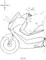
- Fig. 4 is a left side view of a front part of the saddle riding type vehicle 1.
- a distance D1 in the front-back direction between the rear ends E3 of the handles 11 and the front end E1 of the seat 16 is smaller than a distance D2 in the front-back direction between an upper end E4 of the rear edge B1 of the front cover portion 171 and the rear ends E3 of the handle 11.
- the saddle riding type vehicle 1 has a compact vehicle body in the front-back direction.
- the rear ends E3 of the handles 11 here refer to the rear ends of the handles 11 when the handles 11 are not rotated, in other words, when the rear ends of the left and right handles 11 are in the same position in the front-back direction.
- Fig. 5 is a plan view of a periphery of the arch portion 174 of the saddle riding type vehicle 1.
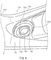
- Fig. 6 is a perspective view of the rear part 174r of the arch portion 174 as seen from the upper left.
- Fig. 7 is a front sectional view of the rear part 174r of the arch portion 174 and the fuel tank 19. In Figs. 6 and 7 , the fuel cap 193 of the fuel tank 19 is not shown.
- the fuel cap 193 of the fuel tank 19 is exposed at an upper surface of the rear part 174r of the arch portion 174.
- the fuel cap 193 is in a position that overlaps a straight line HL passing through the rear ends E3 of the handles 11 in a plan view.
- the rear part 174r of the arch portion 174 is provided with a cap arrangement portion 1741, a filler hole 1742, and two plates 1743.
- the cap arrangement portion 1741 has a circular concave shape.
- the fuel cap 193 is fitted to the fuel inlet 1921 of the filler portion 192, the fuel cap 193 is positioned inside the cap arrangement portion 1741.
- a gap is preferably generated between an inner wall surface of the cap arrangement portion 1741 and a side surface of the fuel cap 193. This makes it easy to remove the fuel cap 193.
- the filler hole 1742 is formed inside the cap arrangement portion 1741.
- the filler hole 1742 is a long hole whose length in the front-back direction is greater than that in the left-right direction according to the embodiment, but the shape of the filler hole 1742 is not particularly limited.
- the two plates 1743 extend downward from a periphery of the filler hole 1742. According to the embodiment, the two plates 1743 are symmetric with respect to a vertical plane VS through a center of the filler hole 1742 and extending in the front-back direction. However, the number and position of the plates 1743 are not particularly limited. The shape of each of the plates 1743 is not particularly limited.
- the filler portion 192 When the fuel tank 19 is assembled to the vehicle body cover 17, the filler portion 192 is inserted into the filler hole 1742 from under, and the fuel inlet 1921 of the filler portion 192 is projected above from the filler hole 1742. At the time, the two plates 1743 contact the surface of the filler cover 194 mounted to the filler portion 192. When the filler cover 194 is not mounted on the filler portion 192, the two plates 1743 contact a surface of the filler portion 192. In this way, the filler portion 192 is positioned. When the fuel cap 193 is fitted to the fuel inlet 1921 projecting from the filler hole 1742, the fuel cap 193 is provided at the upper surface of the rear part 174r of the arch portion 174 as shown in Fig. 5 .
- the front part 174f of the arch portion 174 has its upper edge inclined backward and downward from the lower end E2 of the rear edge B1 of the front cover portion 171 in a side view.
- the rear part 174r of the arch portion 174 has its upper edge inclined forward and downward from the front end E1 of the seat 16 positioned below the lower end E2 of the rear edge B1 of the front cover portion 171 in a side view.
- the height of the arch portion 174 as a whole is reduced.
- the fuel cap 193 of the fuel tank 19 is exposed at the upper surface of the rear part 174r of the arch portion 174, so that a sufficient length in the front-back direction can be secured for the rear part 174r. Therefore, in the saddle riding type vehicle 1, the height of the arch portion 174 as a whole can be prevented from increasing, which makes it easier for a rider to straddle the arch portion 174, so that comfort in getting on and off from the vehicle can be improved.
- the fuel cap 193 of the fuel tank 19 is exposed at the upper surface of the rear part 174r of the arch portion 174, so that a lid used to cover the fuel cap 193 is not provided at the arch portion 174. This can prevent the height of the arch portion 174 from increasing and comfort in getting on and off from the vehicle can be improved. In addition, the fuel cap 193 is exposed and therefore the operation of refueling the fuel tank 19 is simplified.
- the upper edge of the rear part 174r of the arch portion 174 and the upper edge of the front part 16f of the seat 16 form a substantially stepless smooth slope line in a side view. This can make the arch portion 174 easier for a rider to straddle to be seated, so that comfort in getting on and off from the vehicle can be even more improved.
- the fuel tank 19 is provided in front of the seat 16, so that the tank main body 191 can have a sufficient capacity and a sufficient storage space S1 can be secured under the seat 16.
- a part of the hinge 40 is provided in front of the front end E1 of the seat 16. In this way, a large storage space S1 can be secured under the seat 16 without increasing the size of the vehicle body. Furthermore, in the saddle riding type vehicle 1, the fuel cap 193 of the fuel tank 19 is exposed at the upper surface of the rear part 174r of the arch portion 174. Therefore, in the saddle riding type vehicle 1, the position to provide the fuel cap 193 is less likely to be limited by providing the hinge 40 than a vehicle having a lid used to cover a fuel cap. Therefore, the vehicle body can be even more reduced in size.
- the filler portion 192 of the fuel tank 19 overlaps the upper left frame 183L and the upper right frame 183R in a side view. More specifically, the filler portion 192 is positioned relatively in a high position. Therefore, the size of the tank main body 191 in the up-down direction can be increased, so that the tank main body 191 can have a greater capacity.
- the fuel cap 193 of the fuel tank 19 is provided in a position to overlap the straight line HL passing through the rear ends E3 of the left and right handles 11 in a plan view.
- the fuel cap 193 is therefore provided near the front end E1 of the seat 16.
- the rear part 174r of the arch portion 174 provided with the fuel cap 193 has its upper edge extended backward and obliquely upward in a plan view, and therefore the fuel cap 193 is provided in a higher position as it is closer to the front end E1 of the seat 16.
- the tank main body 191 can have an increased size in the up-down direction and thus a greater capacity.
- the arch portion 174 has plates 1743 that extend downward from the periphery of the filler hole 1742.
- the plates 1743 are allowed to contact the surface of the filler portion 192 of the fuel tank 19, so that the fuel tank 19 can be positioned easily.
- the joint J1 between the upper half body 1911 and the lower half body 1912 of the fuel tank 19 is inclined backward and upward in a side view. Therefore, if the inlet of the pump main body 71 is provided at a front and lower part of the tank main body 191, fuel in the fuel tank 19 can be used fully.
- the joint J1 between the upper half body 1911 and the lower half body 1912 of the fuel tank 19 is approximately parallel to the upper edge of the rear part 174r of the arch portion 174 in a side view. More specifically, the tank main body 191 of the fuel tank 19 is provided so that the upper surface of the tank main body 191 is provided along the rear part 174r of the arch portion 174. Therefore, the unused space between the tank main body 191 and the rear part 174r of the arch portion 174 is reduced, so that the fuel tank 19 can have an increased capacity.
- the fuel pump unit 70 is attached to the lower surface of the fuel tank 19, and the fuel hose 80 runs under the fuel tank 19 and is connected to the fuel pump unit 70. Therefore, the upper surface of the fuel tank 19 can be near the arch portion 174 and the capacity of the fuel tank 19 can be increased as compared to the case of providing a fuel hose and a fuel pump unit at an upper surface of a fuel tank.
- the lower surface of the fuel tank 19 has the projection 1912a that projects downward and at least a part of the fuel hose 80 is provided behind the projection 1912a.
- the fuel hose 80 overlaps the projection 1912a in a front view. In this way, the fuel hose 80 can be protected against jumping stones and the like.
- the saddle riding type vehicle 1 has a compact vehicle body while it can secure a sufficient capacity for the fuel tank and a sufficient storage space, and the comfort in getting on and off from the vehicle can be improved.
- the fuel cap of the fuel tank is provided in the position that overlaps the straight line through the rear ends of the left and right handles in a plan view, but the position of the fuel cap at the upper surface of the rear part of the arch portion is not particularly limited.
- a part of the hinge is provided in front of the front end of the seat, but the position of the hinge is not particularly limited.
- the entire hinge may be provided in front of the front end of the seat or the entire hinge may be provided behind the front end of the seat.
- the upper edge of the rear part of the arch portion and the upper edge of the front part of the seat form a substantially stepless smooth slope line in a side view.
- the fuel tank is provided in a forward inclined state and the joint between the upper half body and the lower half body is arranged substantially parallel to the upper edge of the rear part of the arch portion in a side view.
- the fuel tank arrangement is not limited to this.
- the fuel tank may be inclined backward so that the joint of the fuel tank is inclined backward and downward in a side view or the fuel tank may be provided with no inclination so that the joint of the fuel tank is level in a side view.
- the projection included in the lower surface of the lower half body is positioned at the front part of the lower half body.
- the position of the projection is not particularly limited.
- the projection is provided from the left end to the right end of the lower half body.
- the projection may be provided at the left or right half of the lower half body or only at a center part of the lower half body in the vehicle-widthwise direction. The projection does not have to be included in the lower surface of the lower half body.
- the filler portion overlaps the upper left frame and he upper right frame in a side view.
- the position of the filler portion is not particularly limited.
- the filler portion may be provided above or below the upper left frame and the upper right frame.
- the plates that extend downward from the periphery of the filler hole are provided at the rear part of the arch portion in order to position the filler portion and the fuel cap, but the plates do not have to be provided.
- the state of "extending upward” or “extending downward” needs only include a component in an up-down direction. This includes not only a configuration extending in the exact up-down direction but also a configuration extending obliquely with respect to the exact up-down direction.
- the state of "projecting downward” needs only include a component in an up-down direction. This includes not only a configuration projecting in the exact up-down direction but also a configuration projecting obliquely with respect to the exact up-down direction.
- the state of "extending backward” or “extending in the front-back direction” needs only include a component in a front-back direction. This includes not only a configuration extending in the exact front-back direction but also a configuration extending obliquely with respect to the exact front-back direction.
- the state of "extending outward in the vehicle-widthwise direction” needs only a component in a vehicle-widthwise direction. This includes not only a configuration extending in the exact vehicle-widthwise direction but also a configuration extending obliquely with respect to the exact vehicle-widthwise direction.
- portions of means. According to the present teaching said term referrers to a section of an element or member and, alternatively, to an individual member.
Landscapes
- Engineering & Computer Science (AREA)
- Mechanical Engineering (AREA)
- Automatic Cycles, And Cycles In General (AREA)
Claims (10)
- Véhicule du type à selle comprenant :des poignées (11) ;un arbre de direction (12) qui s'étend vers le bas à partir des poignées (11) ;une partie de tuyau de tête (181) dans laquelle est inséré l'arbre de direction (12) ;un siège (16) disposé derrière les poignées (11) ;un espace de rangement (S1) disposé en dessous du siège (16) ;un réservoir de carburant (19) comportant une entrée de carburant (1921) et un bouchon de réservoir de carburant (193) utilisé pour boucher l'entrée de carburant (1921) ; etun capot de carrosserie de véhicule (17),le capot de carrosserie de véhicule (17) incluant :une partie de capot avant (171) disposée en dessous des poignées (11) pour contenir au moins une partie de l'arbre de direction (12) et la partie de tuyau de tête (181) ;une partie d'arc (174) disposée de manière à s'étendre dans la direction avant-arrière entre la partie de capot avant (171) et le siège (16) et recouvrir le réservoir de carburant (19) par dessus, la partie d'arc (174) ayant une forme convexe en coupe frontale ; etune partie de marchepied (175) disposée au niveau de chacune des parties d'arc droite et gauche (174) et reliée à l'extrémité inférieure de la partie d'arc (174),la partie de capot avant (171) comportant un bord arrière (B1) s'étendant dans la direction haut-bas, vue de côté,la distance (D1) entre les extrémités arrière (E3) des poignées (11) et l'extrémité avant (E1) du siège (16) dans la direction avant-arrière étant plus petite que la distance (D2) entre l'extrémité supérieure (E4) du bord arrière (B1) de la partie de capot avant (171) et les extrémités arrières (E3) des poignées (11) dans la direction avant-arrière, vue de côté,la partie d'arc (174) comportant une partie avant (174f) ayant un bord supérieur incliné vers l'arrière et vers le bas et une partie arrière (174r) ayant un bord supérieur incliné vers l'arrière et vers le haut, vue de côté, caractérisé en ce que le bouchon de réservoir de carburant (193) est exposé au niveau de la surface supérieure de la partie arrière (174r) de la partie d'arc (174).
- Véhicule du type à selle selon la revendication 1, caractérisé par
une articulation (40) utilisée pour supporter la partie avant (16f) du siège (16), de façon que le siège (16) puisse tourner dans la direction haut-bas,
au moins une partie de l'articulation (40) étant disposée devant l'extrémité avant (E1) du siège (16). - Véhicule du type à selle selon la revendication 1 ou 2, caractérisé en ce que le bord supérieur de la partie avant (16f) du siège (16) est continu avec le bord supérieur de la partie arrière (174r) de la partie d'arc (174) et s'étend vers l'arrière et vers le haut, vu de côté.
- Véhicule du type à selle selon l'une quelconque des revendications 1 à 3, caractérisé par des poignées gauche et droite (11), dans lequel le bouchon de réservoir de carburant (193) est disposé dans une position qui recouvre une ligne droite (HL) passant par les extrémités arrière (E3) des poignées gauche et droite (11), en vue plane.
- Véhicule du type à selle selon l'une quelconque des revendications 1 à 4, caractérisé par un cadre (183L, 183R) disposé dans la partie d'arc (174) s'étendant dans la direction avant-arrière,
le réservoir de carburant (19) incluant :un corps principal de réservoir (191) ; etune partie de filtre (192) reliée au corps principal de réservoir (191) et comportant l'entrée de carburant (1921) à son extrémité supérieure,la partie de filtre (192) recouvrant le cadre (183L, 183R), vu de côté. - Véhicule du type à selle selon la revendication 5, caractérisé en ce que la partie d'arc (174) comporte :un trou (1742) formé au niveau de la surface supérieure de la partie arrière pour exposer le bouchon de réservoir de carburant (193) ; etune plaque (1743) disposée de manière à s'étendre vers le bas depuis la périphérie du trou (1742) et en contact avec la surface latérale de la partie de filtre (192).
- Véhicule du type à selle selon l'une quelconque des revendications 1 à 6, caractérisé en ce que le réservoir de carburant (19) comporte :un demi-corps supérieur (1911) conformé sous forme convexe ; etun demi-corps inférieur (1912) conformé sous forme concave et ayant une partie périphérique d'extrémité supérieure reliée à une partie périphérique d'extrémité inférieure du demi-corps supérieur (1911), etla partie de liaison entre le demi-corps supérieur (1911) et le demi-corps inférieur (1912) est inclinée vers l'arrière et vers le haut, vue de côté.
- Véhicule du type à selle selon la revendication 7, caractérisé en ce que la partie de liaison entre le demi-corps supérieur (1911) et le demi-corps inférieur (1912) est sensiblement parallèle au bord supérieur de la partie arrière (174r) de la partie d'arc (174), vue de côté.
- Véhicule du type à selle selon l'une quelconque des revendications 1 à 8, caractérisé par une unité de pompe de carburant (70) fixée à la surface inférieure du réservoir de carburant (19) ; et
un tuyau de carburant (80) passant sous le réservoir de carburant (19) et relié à l'unité de pompe de carburant (70). - Véhicule du type à selle selon la revendication 9, caractérisé en ce que la surface inférieure du réservoir de carburant (19) comporte une projection (1912a) qui se projette vers le bas, et
au moins une partie du tuyau de carburant (80) est disposée derrière la projection (1912a) dans une position qui recouvre la projection (1912a), vue de face.
Applications Claiming Priority (1)
| Application Number | Priority Date | Filing Date | Title |
|---|---|---|---|
| JP2013229981A JP2015089713A (ja) | 2013-11-06 | 2013-11-06 | 鞍乗型車両 |
Publications (2)
| Publication Number | Publication Date |
|---|---|
| EP2871121A1 EP2871121A1 (fr) | 2015-05-13 |
| EP2871121B1 true EP2871121B1 (fr) | 2016-02-17 |
Family
ID=51398535
Family Applications (1)
| Application Number | Title | Priority Date | Filing Date |
|---|---|---|---|
| EP14182251.0A Active EP2871121B1 (fr) | 2013-11-06 | 2014-08-26 | Véhicule de type à selle |
Country Status (4)
| Country | Link |
|---|---|
| EP (1) | EP2871121B1 (fr) |
| JP (1) | JP2015089713A (fr) |
| ES (1) | ES2563746T3 (fr) |
| TW (1) | TWI529088B (fr) |
Families Citing this family (6)
| Publication number | Priority date | Publication date | Assignee | Title |
|---|---|---|---|---|
| CN111448128B (zh) * | 2017-12-14 | 2021-10-08 | 本田技研工业株式会社 | 跨骑型车辆 |
| JP7198357B2 (ja) * | 2019-07-10 | 2022-12-28 | 本田技研工業株式会社 | 鞍乗型電動車両 |
| JP6964723B1 (ja) | 2020-06-23 | 2021-11-10 | ヤマハ発動機株式会社 | 鞍乗型車両 |
| JP6824463B1 (ja) | 2020-06-23 | 2021-02-03 | ヤマハ発動機株式会社 | 鞍乗型車両 |
| WO2022070519A1 (fr) * | 2020-09-30 | 2022-04-07 | 本田技研工業株式会社 | Structure de capot de carrosserie de véhicule pour un véhicule de type à selle |
| JP2024118028A (ja) | 2023-02-20 | 2024-08-30 | カワサキモータース株式会社 | 鞍乗型車両 |
Family Cites Families (3)
| Publication number | Priority date | Publication date | Assignee | Title |
|---|---|---|---|---|
| JPH0796394B2 (ja) * | 1985-10-04 | 1995-10-18 | 本田技研工業株式会社 | 低床式自動二・三輪車のフユ−エルタンク配置構造 |
| JP2880525B2 (ja) * | 1989-06-16 | 1999-04-12 | ヤマハ発動機株式会社 | スクータ型自動二輪車 |
| JP5411241B2 (ja) | 2011-11-24 | 2014-02-12 | 本田技研工業株式会社 | 鞍乗り型車両 |
-
2013
- 2013-11-06 JP JP2013229981A patent/JP2015089713A/ja active Pending
-
2014
- 2014-08-26 EP EP14182251.0A patent/EP2871121B1/fr active Active
- 2014-08-26 ES ES14182251.0T patent/ES2563746T3/es active Active
- 2014-08-28 TW TW103129747A patent/TWI529088B/zh active
Also Published As
| Publication number | Publication date |
|---|---|
| EP2871121A1 (fr) | 2015-05-13 |
| JP2015089713A (ja) | 2015-05-11 |
| ES2563746T3 (es) | 2016-03-16 |
| TWI529088B (zh) | 2016-04-11 |
| TW201522149A (zh) | 2015-06-16 |
Similar Documents
| Publication | Publication Date | Title |
|---|---|---|
| EP2871121A1 (fr) | Véhicule de type à selle | |
| EP2176115B1 (fr) | Véhicule de type scooter | |
| JP2015058740A (ja) | 電動車両 | |
| JP6167151B2 (ja) | 鞍乗り型車両 | |
| JP2010188758A (ja) | 自動二輪車 | |
| EP2179912B1 (fr) | Véhicule de type scooter | |
| JP5727911B2 (ja) | 鞍乗型車両の後部構造 | |
| JP6187158B2 (ja) | フロントフェンダーの補強構造 | |
| JP2010215214A (ja) | スクータ型車両 | |
| ES2606661T3 (es) | Vehículo del tipo de montar a horcajadas | |
| EP2679476B1 (fr) | Motocyclette | |
| US9428238B2 (en) | Body frame structure for saddle type vehicle | |
| EP4112430B1 (fr) | Véhicule de type à selle | |
| JP6883063B2 (ja) | 鞍乗り型車両 | |
| EP3000702B1 (fr) | Véhicule de type à enfourcher | |
| EP3305642B1 (fr) | Véhicule à enfourcher | |
| EP3636532B1 (fr) | Véhicule à enfourcher | |
| JP7671805B2 (ja) | 鞍乗り型車両 | |
| JP2013244878A (ja) | 鞍乗型車両 | |
| TWI837561B (zh) | 跨坐型車輛 | |
| JP6108986B2 (ja) | 鞍乗型車両の収納ボックス構造 | |
| JP2013136306A (ja) | 鞍乗型車両 | |
| JP6723280B2 (ja) | 鞍乗型車両 | |
| JP6051186B2 (ja) | ハンドルカバー構造 | |
| JP2018058467A (ja) | 鞍乗型車両 |
Legal Events
| Date | Code | Title | Description |
|---|---|---|---|
| PUAI | Public reference made under article 153(3) epc to a published international application that has entered the european phase |
Free format text: ORIGINAL CODE: 0009012 |
|
| 17P | Request for examination filed |
Effective date: 20140826 |
|
| AK | Designated contracting states |
Kind code of ref document: A1 Designated state(s): AL AT BE BG CH CY CZ DE DK EE ES FI FR GB GR HR HU IE IS IT LI LT LU LV MC MK MT NL NO PL PT RO RS SE SI SK SM TR |
|
| AX | Request for extension of the european patent |
Extension state: BA ME |
|
| R17P | Request for examination filed (corrected) |
Effective date: 20150609 |
|
| RBV | Designated contracting states (corrected) |
Designated state(s): AL AT BE BG CH CY CZ DE DK EE ES FI FR GB GR HR HU IE IS IT LI LT LU LV MC MK MT NL NO PL PT RO RS SE SI SK SM TR |
|
| RIC1 | Information provided on ipc code assigned before grant |
Ipc: B62J 17/06 20060101AFI20150717BHEP Ipc: B62J 35/00 20060101ALI20150717BHEP |
|
| GRAP | Despatch of communication of intention to grant a patent |
Free format text: ORIGINAL CODE: EPIDOSNIGR1 |
|
| INTG | Intention to grant announced |
Effective date: 20150918 |
|
| GRAS | Grant fee paid |
Free format text: ORIGINAL CODE: EPIDOSNIGR3 |
|
| GRAA | (expected) grant |
Free format text: ORIGINAL CODE: 0009210 |
|
| AK | Designated contracting states |
Kind code of ref document: B1 Designated state(s): AL AT BE BG CH CY CZ DE DK EE ES FI FR GB GR HR HU IE IS IT LI LT LU LV MC MK MT NL NO PL PT RO RS SE SI SK SM TR |
|
| REG | Reference to a national code |
Ref country code: GB Ref legal event code: FG4D |
|
| REG | Reference to a national code |
Ref country code: CH Ref legal event code: EP |
|
| REG | Reference to a national code |
Ref country code: IE Ref legal event code: FG4D |
|
| REG | Reference to a national code |
Ref country code: AT Ref legal event code: REF Ref document number: 775507 Country of ref document: AT Kind code of ref document: T Effective date: 20160315 |
|
| REG | Reference to a national code |
Ref country code: ES Ref legal event code: FG2A Ref document number: 2563746 Country of ref document: ES Kind code of ref document: T3 Effective date: 20160316 |
|
| REG | Reference to a national code |
Ref country code: DE Ref legal event code: R096 Ref document number: 602014000911 Country of ref document: DE |
|
| REG | Reference to a national code |
Ref country code: NL Ref legal event code: MP Effective date: 20160217 |
|
| REG | Reference to a national code |
Ref country code: LT Ref legal event code: MG4D |
|
| REG | Reference to a national code |
Ref country code: AT Ref legal event code: MK05 Ref document number: 775507 Country of ref document: AT Kind code of ref document: T Effective date: 20160217 |
|
| PG25 | Lapsed in a contracting state [announced via postgrant information from national office to epo] |
Ref country code: HR Free format text: LAPSE BECAUSE OF FAILURE TO SUBMIT A TRANSLATION OF THE DESCRIPTION OR TO PAY THE FEE WITHIN THE PRESCRIBED TIME-LIMIT Effective date: 20160217 Ref country code: NO Free format text: LAPSE BECAUSE OF FAILURE TO SUBMIT A TRANSLATION OF THE DESCRIPTION OR TO PAY THE FEE WITHIN THE PRESCRIBED TIME-LIMIT Effective date: 20160517 Ref country code: FI Free format text: LAPSE BECAUSE OF FAILURE TO SUBMIT A TRANSLATION OF THE DESCRIPTION OR TO PAY THE FEE WITHIN THE PRESCRIBED TIME-LIMIT Effective date: 20160217 Ref country code: GR Free format text: LAPSE BECAUSE OF FAILURE TO SUBMIT A TRANSLATION OF THE DESCRIPTION OR TO PAY THE FEE WITHIN THE PRESCRIBED TIME-LIMIT Effective date: 20160518 |
|
| REG | Reference to a national code |
Ref country code: FR Ref legal event code: PLFP Year of fee payment: 3 |
|
| PG25 | Lapsed in a contracting state [announced via postgrant information from national office to epo] |
Ref country code: SE Free format text: LAPSE BECAUSE OF FAILURE TO SUBMIT A TRANSLATION OF THE DESCRIPTION OR TO PAY THE FEE WITHIN THE PRESCRIBED TIME-LIMIT Effective date: 20160217 Ref country code: AT Free format text: LAPSE BECAUSE OF FAILURE TO SUBMIT A TRANSLATION OF THE DESCRIPTION OR TO PAY THE FEE WITHIN THE PRESCRIBED TIME-LIMIT Effective date: 20160217 Ref country code: LT Free format text: LAPSE BECAUSE OF FAILURE TO SUBMIT A TRANSLATION OF THE DESCRIPTION OR TO PAY THE FEE WITHIN THE PRESCRIBED TIME-LIMIT Effective date: 20160217 Ref country code: RS Free format text: LAPSE BECAUSE OF FAILURE TO SUBMIT A TRANSLATION OF THE DESCRIPTION OR TO PAY THE FEE WITHIN THE PRESCRIBED TIME-LIMIT Effective date: 20160217 Ref country code: LV Free format text: LAPSE BECAUSE OF FAILURE TO SUBMIT A TRANSLATION OF THE DESCRIPTION OR TO PAY THE FEE WITHIN THE PRESCRIBED TIME-LIMIT Effective date: 20160217 Ref country code: NL Free format text: LAPSE BECAUSE OF FAILURE TO SUBMIT A TRANSLATION OF THE DESCRIPTION OR TO PAY THE FEE WITHIN THE PRESCRIBED TIME-LIMIT Effective date: 20160217 Ref country code: PT Free format text: LAPSE BECAUSE OF FAILURE TO SUBMIT A TRANSLATION OF THE DESCRIPTION OR TO PAY THE FEE WITHIN THE PRESCRIBED TIME-LIMIT Effective date: 20160617 Ref country code: PL Free format text: LAPSE BECAUSE OF FAILURE TO SUBMIT A TRANSLATION OF THE DESCRIPTION OR TO PAY THE FEE WITHIN THE PRESCRIBED TIME-LIMIT Effective date: 20160217 |
|
| PG25 | Lapsed in a contracting state [announced via postgrant information from national office to epo] |
Ref country code: EE Free format text: LAPSE BECAUSE OF FAILURE TO SUBMIT A TRANSLATION OF THE DESCRIPTION OR TO PAY THE FEE WITHIN THE PRESCRIBED TIME-LIMIT Effective date: 20160217 Ref country code: DK Free format text: LAPSE BECAUSE OF FAILURE TO SUBMIT A TRANSLATION OF THE DESCRIPTION OR TO PAY THE FEE WITHIN THE PRESCRIBED TIME-LIMIT Effective date: 20160217 |
|
| REG | Reference to a national code |
Ref country code: DE Ref legal event code: R097 Ref document number: 602014000911 Country of ref document: DE |
|
| PG25 | Lapsed in a contracting state [announced via postgrant information from national office to epo] |
Ref country code: SM Free format text: LAPSE BECAUSE OF FAILURE TO SUBMIT A TRANSLATION OF THE DESCRIPTION OR TO PAY THE FEE WITHIN THE PRESCRIBED TIME-LIMIT Effective date: 20160217 Ref country code: SK Free format text: LAPSE BECAUSE OF FAILURE TO SUBMIT A TRANSLATION OF THE DESCRIPTION OR TO PAY THE FEE WITHIN THE PRESCRIBED TIME-LIMIT Effective date: 20160217 Ref country code: CZ Free format text: LAPSE BECAUSE OF FAILURE TO SUBMIT A TRANSLATION OF THE DESCRIPTION OR TO PAY THE FEE WITHIN THE PRESCRIBED TIME-LIMIT Effective date: 20160217 Ref country code: RO Free format text: LAPSE BECAUSE OF FAILURE TO SUBMIT A TRANSLATION OF THE DESCRIPTION OR TO PAY THE FEE WITHIN THE PRESCRIBED TIME-LIMIT Effective date: 20160217 |
|
| PLBE | No opposition filed within time limit |
Free format text: ORIGINAL CODE: 0009261 |
|
| STAA | Information on the status of an ep patent application or granted ep patent |
Free format text: STATUS: NO OPPOSITION FILED WITHIN TIME LIMIT |
|
| PG25 | Lapsed in a contracting state [announced via postgrant information from national office to epo] |
Ref country code: BE Free format text: LAPSE BECAUSE OF FAILURE TO SUBMIT A TRANSLATION OF THE DESCRIPTION OR TO PAY THE FEE WITHIN THE PRESCRIBED TIME-LIMIT Effective date: 20160217 |
|
| 26N | No opposition filed |
Effective date: 20161118 |
|
| PG25 | Lapsed in a contracting state [announced via postgrant information from national office to epo] |
Ref country code: BG Free format text: LAPSE BECAUSE OF FAILURE TO SUBMIT A TRANSLATION OF THE DESCRIPTION OR TO PAY THE FEE WITHIN THE PRESCRIBED TIME-LIMIT Effective date: 20160517 Ref country code: SI Free format text: LAPSE BECAUSE OF FAILURE TO SUBMIT A TRANSLATION OF THE DESCRIPTION OR TO PAY THE FEE WITHIN THE PRESCRIBED TIME-LIMIT Effective date: 20160217 |
|
| PG25 | Lapsed in a contracting state [announced via postgrant information from national office to epo] |
Ref country code: MC Free format text: LAPSE BECAUSE OF FAILURE TO SUBMIT A TRANSLATION OF THE DESCRIPTION OR TO PAY THE FEE WITHIN THE PRESCRIBED TIME-LIMIT Effective date: 20160217 |
|
| REG | Reference to a national code |
Ref country code: IE Ref legal event code: MM4A |
|
| PG25 | Lapsed in a contracting state [announced via postgrant information from national office to epo] |
Ref country code: IE Free format text: LAPSE BECAUSE OF NON-PAYMENT OF DUE FEES Effective date: 20160826 |
|
| REG | Reference to a national code |
Ref country code: FR Ref legal event code: PLFP Year of fee payment: 4 |
|
| PG25 | Lapsed in a contracting state [announced via postgrant information from national office to epo] |
Ref country code: LU Free format text: LAPSE BECAUSE OF NON-PAYMENT OF DUE FEES Effective date: 20160826 |
|
| REG | Reference to a national code |
Ref country code: CH Ref legal event code: PL |
|
| PG25 | Lapsed in a contracting state [announced via postgrant information from national office to epo] |
Ref country code: LI Free format text: LAPSE BECAUSE OF NON-PAYMENT OF DUE FEES Effective date: 20170831 Ref country code: CH Free format text: LAPSE BECAUSE OF NON-PAYMENT OF DUE FEES Effective date: 20170831 |
|
| PG25 | Lapsed in a contracting state [announced via postgrant information from national office to epo] |
Ref country code: HU Free format text: LAPSE BECAUSE OF FAILURE TO SUBMIT A TRANSLATION OF THE DESCRIPTION OR TO PAY THE FEE WITHIN THE PRESCRIBED TIME-LIMIT; INVALID AB INITIO Effective date: 20140826 |
|
| PG25 | Lapsed in a contracting state [announced via postgrant information from national office to epo] |
Ref country code: IS Free format text: LAPSE BECAUSE OF FAILURE TO SUBMIT A TRANSLATION OF THE DESCRIPTION OR TO PAY THE FEE WITHIN THE PRESCRIBED TIME-LIMIT Effective date: 20160217 Ref country code: MK Free format text: LAPSE BECAUSE OF FAILURE TO SUBMIT A TRANSLATION OF THE DESCRIPTION OR TO PAY THE FEE WITHIN THE PRESCRIBED TIME-LIMIT Effective date: 20160217 Ref country code: CY Free format text: LAPSE BECAUSE OF FAILURE TO SUBMIT A TRANSLATION OF THE DESCRIPTION OR TO PAY THE FEE WITHIN THE PRESCRIBED TIME-LIMIT Effective date: 20160217 Ref country code: MT Free format text: LAPSE BECAUSE OF NON-PAYMENT OF DUE FEES Effective date: 20160831 |
|
| REG | Reference to a national code |
Ref country code: FR Ref legal event code: PLFP Year of fee payment: 5 |
|
| PG25 | Lapsed in a contracting state [announced via postgrant information from national office to epo] |
Ref country code: AL Free format text: LAPSE BECAUSE OF FAILURE TO SUBMIT A TRANSLATION OF THE DESCRIPTION OR TO PAY THE FEE WITHIN THE PRESCRIBED TIME-LIMIT Effective date: 20160217 Ref country code: TR Free format text: LAPSE BECAUSE OF FAILURE TO SUBMIT A TRANSLATION OF THE DESCRIPTION OR TO PAY THE FEE WITHIN THE PRESCRIBED TIME-LIMIT Effective date: 20160217 |
|
| GBPC | Gb: european patent ceased through non-payment of renewal fee |
Effective date: 20180826 |
|
| PG25 | Lapsed in a contracting state [announced via postgrant information from national office to epo] |
Ref country code: GB Free format text: LAPSE BECAUSE OF NON-PAYMENT OF DUE FEES Effective date: 20180826 |
|
| PGFP | Annual fee paid to national office [announced via postgrant information from national office to epo] |
Ref country code: ES Payment date: 20201023 Year of fee payment: 7 |
|
| REG | Reference to a national code |
Ref country code: ES Ref legal event code: FD2A Effective date: 20221027 |
|
| PG25 | Lapsed in a contracting state [announced via postgrant information from national office to epo] |
Ref country code: ES Free format text: LAPSE BECAUSE OF NON-PAYMENT OF DUE FEES Effective date: 20210827 |
|
| P01 | Opt-out of the competence of the unified patent court (upc) registered |
Effective date: 20230527 |
|
| PGFP | Annual fee paid to national office [announced via postgrant information from national office to epo] |
Ref country code: DE Payment date: 20250820 Year of fee payment: 12 |
|
| PGFP | Annual fee paid to national office [announced via postgrant information from national office to epo] |
Ref country code: IT Payment date: 20250825 Year of fee payment: 12 |
|
| PGFP | Annual fee paid to national office [announced via postgrant information from national office to epo] |
Ref country code: FR Payment date: 20250829 Year of fee payment: 12 |