EP2871312B1 - Dispositif d'aération par entrebâillement pour porte ou fenêtre coulissante et porte ou fenêtre coulissante - Google Patents
Dispositif d'aération par entrebâillement pour porte ou fenêtre coulissante et porte ou fenêtre coulissante Download PDFInfo
- Publication number
- EP2871312B1 EP2871312B1 EP13192304.7A EP13192304A EP2871312B1 EP 2871312 B1 EP2871312 B1 EP 2871312B1 EP 13192304 A EP13192304 A EP 13192304A EP 2871312 B1 EP2871312 B1 EP 2871312B1
- Authority
- EP
- European Patent Office
- Prior art keywords
- sliding
- gap ventilation
- sliding door
- gap
- ventilation
- Prior art date
- Legal status (The legal status is an assumption and is not a legal conclusion. Google has not performed a legal analysis and makes no representation as to the accuracy of the status listed.)
- Active
Links
Images



Classifications
-
- E—FIXED CONSTRUCTIONS
- E05—LOCKS; KEYS; WINDOW OR DOOR FITTINGS; SAFES
- E05D—HINGES OR SUSPENSION DEVICES FOR DOORS, WINDOWS OR WINGS
- E05D15/00—Suspension arrangements for wings
- E05D15/06—Suspension arrangements for wings for wings sliding horizontally more or less in their own plane
- E05D15/10—Suspension arrangements for wings for wings sliding horizontally more or less in their own plane movable out of one plane into a second parallel plane
-
- E—FIXED CONSTRUCTIONS
- E05—LOCKS; KEYS; WINDOW OR DOOR FITTINGS; SAFES
- E05D—HINGES OR SUSPENSION DEVICES FOR DOORS, WINDOWS OR WINGS
- E05D13/00—Accessories for sliding or lifting wings, e.g. pulleys, safety catches
- E05D13/04—Fasteners specially adapted for holding sliding wings open
-
- E—FIXED CONSTRUCTIONS
- E05—LOCKS; KEYS; WINDOW OR DOOR FITTINGS; SAFES
- E05D—HINGES OR SUSPENSION DEVICES FOR DOORS, WINDOWS OR WINGS
- E05D15/00—Suspension arrangements for wings
- E05D15/06—Suspension arrangements for wings for wings sliding horizontally more or less in their own plane
- E05D15/10—Suspension arrangements for wings for wings sliding horizontally more or less in their own plane movable out of one plane into a second parallel plane
- E05D2015/1028—Suspension arrangements for wings for wings sliding horizontally more or less in their own plane movable out of one plane into a second parallel plane with only the wing moving transversely
- E05D2015/1039—Suspension arrangements for wings for wings sliding horizontally more or less in their own plane movable out of one plane into a second parallel plane with only the wing moving transversely the wing sliding transversely on the carriage
-
- E—FIXED CONSTRUCTIONS
- E05—LOCKS; KEYS; WINDOW OR DOOR FITTINGS; SAFES
- E05F—DEVICES FOR MOVING WINGS INTO OPEN OR CLOSED POSITION; CHECKS FOR WINGS; WING FITTINGS NOT OTHERWISE PROVIDED FOR, CONCERNED WITH THE FUNCTIONING OF THE WING
- E05F11/00—Man-operated mechanisms for operating wings, including those which also operate the fastening
- E05F11/02—Man-operated mechanisms for operating wings, including those which also operate the fastening for wings in general, e.g. fanlights
- E05F11/08—Man-operated mechanisms for operating wings, including those which also operate the fastening for wings in general, e.g. fanlights with longitudinally-moving bars guided, e.g. by pivoted links, in or on the frame
- E05F11/12—Mechanisms by which the bar shifts the wing
- E05F11/14—Mechanisms by which the bar shifts the wing directly, i.e. without links, shifting the wing, e.g. by rack and gear or pin and slot
- E05F11/145—Mechanisms by which the bar shifts the wing directly, i.e. without links, shifting the wing, e.g. by rack and gear or pin and slot by pin and slot
-
- E—FIXED CONSTRUCTIONS
- E05—LOCKS; KEYS; WINDOW OR DOOR FITTINGS; SAFES
- E05Y—INDEXING SCHEME ASSOCIATED WITH SUBCLASSES E05D AND E05F, RELATING TO CONSTRUCTION ELEMENTS, ELECTRIC CONTROL, POWER SUPPLY, POWER SIGNAL OR TRANSMISSION, USER INTERFACES, MOUNTING OR COUPLING, DETAILS, ACCESSORIES, AUXILIARY OPERATIONS NOT OTHERWISE PROVIDED FOR, APPLICATION THEREOF
- E05Y2800/00—Details, accessories and auxiliary operations not otherwise provided for
- E05Y2800/74—Specific positions
- E05Y2800/75—Specific positions intermediate
Definitions
- the invention relates to a sliding door or a sliding window.
- Sliding doors and sliding windows have the problem of sealing the sliding sash with respect to the fixed enclosure, in particular a fixed frame. If a seal between the fixed enclosure and the sliding sash is arranged and the sliding sash is not transversely displaceable to the main plane of the window or the door, it is very difficult to open the sash since its obstruction is hindered by the seal arranged between the sash and the fixed enclosure becomes.
- a sliding door which is guided by means of rollers in a U-shaped rail.
- the rollers are designed as rubber rollers. They cooperate with a sliding element mounted in the rail base element, which has a ramp in its end regions, a recess for the rubber rollers and elastic beads in the central region.
- the object of the present invention is therefore to provide a sliding door or a sliding window with a night ventilation arrangement, by means of which such a night ventilation function can be realized.
- a sliding door or a sliding feast with the features of claim 1. It can also be retrofitted with existing sliding doors or sliding windows, the gap ventilation arrangement. In addition, it is at the discretion of a user where the gap ventilation assembly is positioned. In particular, it can be determined by how large the gap should be for the night ventilation.
- a night ventilation position is to be understood a position of the sliding sash in which he was moved a little way in the sliding direction. In this position, it can be parked or attracted to the fixed enclosure. In the tightened position it is fixed in the night ventilation position.
- An inventively designed sliding or sliding window can be operated with the already existing actuating handle. It is for taking and fixing the night ventilation position or to release the night ventilation position no further actuating handle necessary. This makes the operation very easy and comfortable.
- a gap ventilation arrangement can be provided at the top and bottom of the sliding door or on the sliding window so that the sliding leaf can be held and locked even more reliably in the night ventilation position.
- the slit ventilation assembly may be provided with a slit ventilation member having a mounting portion for fastening the slit ventilation member to the sliding panel or the fixed enclosure and a stop or engagement member for cooperating with a slat ventilation counterpart, the abutment member being movable against a restoring force relative to the attachment portion.
- the gap ventilation part is at least partially formed of an elastic material.
- the inventive night ventilation arrangement it is possible to park a sliding sash of a sliding window or a sliding door a little way parallel from the fixed enclosure and then move in the sliding direction until the gap ventilation part and the gap ventilation counterpart engage with each other or strike each other and thereby a further opening movement the sliding sash is prevented. Subsequently, the sliding leaf can in turn be moved transversely to the fixed enclosure, namely to be moved to the fixed enclosure.
- the slit ventilation counterpart can be a separate component which is arranged on the fixed enclosure or on the wing. However, it can also be provided that the gap ventilation counterpart is part of the fixed enclosure, for example a fixed frame, or is formed thereon.
- the stopper or engagement part is disengaged from the slit ventilation counterpart, so that the sliding sash either closed or can be fully opened, at least relative to the fixed enclosure can be moved.
- the distance between the slit ventilation part and the slit ventilation counterpart is so great that the sliding sash can simply be slid open without the slit ventilation part coming into contact with the slit ventilation counterpart.
- an elastic material has the advantage that no additional return element, such as a spring, must be used.
- the use of an elastic material has the advantage that the stop or engagement part returns to its original position, for example, when it has run over a ramp of a night ventilation counterpart. This can ensure that the wing is "caught" in a gap opening position, ie the further sliding movement is reliably blocked.
- the gap ventilation part is at least partially formed of spring steel.
- the attachment portion and the stopper or engagement member may be integrally formed of spring steel.
- the gap ventilation part has a transversely extending to the main plane nose.
- the nose may be provided in the region of the stop or engagement part and additionally provide for a determination of the sliding leaf in a night ventilation position.
- the stopper or engagement member may abut on the night vent counterpart and the nose may fit into a corresponding receptacle engage the night ventilation counterpart and thereby additionally lock.
- the nose has the advantage that it can slide along a portion of the fixed enclosure without damaging the fixed enclosure, and in particular thereby also keeping the stopper or engagement member at a distance from the fixed enclosure. Thus, damage to the stopper or engagement member during normal sliding opening or closing of the sash can be prevented.
- the nose is formed of resilient material or has a coating of resilient material.
- resilient material for example, plastic or rubber in question. As a result, damage can be even more effectively avoided.
- a fastened to the fixed enclosure or the sliding sash gap ventilation counterpart may be provided which has a stop and / or a recess for the stop or engagement part of the gap ventilation part.
- the gap ventilation counterpart can be arranged on the fixed enclosure, when the gap ventilation part is arranged on the wing and vice versa.
- the slit ventilation counterpart can be positioned almost anywhere, so that different positions for the wing can be adjusted in the night vent position. It can also be provided a plurality of night ventilation counterparts, so that optionally different night ventilation positions can be adjusted.
- the gap ventilation counterpart has a receptacle for the nose of the gap ventilation part.
- the sliding sash in the night ventilation position can be set more reliable.
- the slit ventilation counterpart can have a lead-in bevel leading to the stop and / or the recess.
- the stop or engagement means can be reliably guided to the stop and / or the recess when sliding open the sliding sash. Due to the ramp or ramp, a portion of the gap ventilation part can be deflected against a restoring force transversely to the main plane.
- the slit ventilation counterpart can also have a nose for the nose in the direction of slide opening seen downstream deflection. Accordingly, if a sliding leaf is to be displaced from a gap opening position in the sliding opening direction, the nose can slide along the deflection slope. This prevents the nose from catching on or being caught by the stop of the slit ventilation counterpart, thereby hindering a sliding opening of the sliding sash. Also in this context, it is advantageous if the gap ventilation part is at least partially formed of elastic material.
- the slit ventilation counterpart seen in Schiebesch spacardi before the stop and / or the recess have a ramp for the stop or engagement part. This ensures that, when the sliding leaf is closed, the gap ventilation part runs past the gap ventilation counterpart, in particular does not catch on it.
- the gap ventilation arrangement is arranged in a region of the sliding leaf facing away from a ventilation gap.
- the components of the gap ventilation arrangement can be hidden be arranged and in particular not be visible when the sliding sash is fully opened.
- the gap ventilation part can be fixed when the sliding leaf has a C-shaped groove. At this C-shaped groove, the gap ventilation part can be attached. For this purpose, at least one clamping piece can be provided on the gap ventilation part.
- the fixed enclosure may comprise a guide web, on which the gap ventilation counterpart is arranged.
- the guide bar can be provided with holes into which the gap ventilation counterpart is clipped.
- the gap ventilation counterpart can be riveted or screwed or otherwise secured to the guide bar.
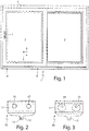
- the FIG. 1 shows a sliding door 1 with a fixed wing 2 and a sliding sash 3 and designed as a frame fixed enclosure 4.
- the sliding sash 3 is schiebeöffenbar in the direction of arrow 5 and closable in the direction of arrow 6.
- actuating handle 7 different switch positions are adjustable. In particular, a locking position, in which the sliding leaf 3 is attracted to the fixed enclosure 4, a partially parked position (intermediate position), in the sliding panel 3 is unlocked and is slidable into the night ventilation position and a (fully) parked position (open position), in which the sliding leaf is freely movable, can be realized. If the wing has been moved to the night ventilation position, it can be attracted via the actuating handle 7 to the fixed enclosure 4 and thereby fixed in position.
- the gap ventilation arrangement according to the invention can be installed at different points, for example, the points 8 and 9 are shown. Preference is given to an installation in the area of the point 9, since thereby the gap ventilation arrangement is not visible even when the sliding leaf 3 is open.
- the gap ventilation arrangement can be installed at the top and / or bottom.
- the FIG. 2 shows a gap ventilation part 10, which has a fixing portion 11 for attachment to the sliding leaf 3 or the fixed enclosure 4. Furthermore, the gap ventilation part 10 has a stop or engagement part 12.
- the stopper or engagement member 12 is movable perpendicular to the plane of the drawing against a restoring force relative to the attachment portion 11.
- the stopper or engagement member 12 is preferably formed of spring steel.
- a nose 13 is provided, which is made of elastic material or includes such.
- FIG. 3 shows the back of the Spaltlteils 10.
- the clamping disks 14, 15 formed as clamping pieces, which are arranged eccentrically rotatable.
- the clamping plates 14, 15 can be rotated via the tool engagements 16, 17, so as to fix the gap ventilation part 10 at a C-groove, for example, the sliding leaf 3 by clamping.
- the fact that provided for fastening clamping plates 14, 15 are, the gap ventilation part 10 also easily from the sliding wing 3 and the fixed enclosure 4 solve and move relative to this, reposition and set in the new position.
- FIG. 4 shows a front view of the Spaltl marssteils 10. The previously described parts are provided with reference numerals.
- FIG. 5 shows a perspective view of a gap ventilation counterpart 20.
- the gap ventilation counterpart 20 has a stop 21 and a recess 22.
- the stop or engagement part 12 strikes against the stop 21 and thereby comes to lie in the recess 22.
- a further movement of the sliding leaf 3 in the opening direction is blocked.
- a receptacle 23 for the nose 13 is provided on the gap ventilation counterpart 20.
- the receptacle 23 is designed in particular as a passage opening.
- a ramp 24 is provided.
- the ramp 24 can deflect the stop or engagement member 12 against a restoring force.
- the stop or engagement part 12 jumps due to the restoring force in the recess 22.
- a deflection bevel 25 for deflecting the nose 13 is provided in the sliding direction seen behind the receptacle 23 .
- the nose 13 can be deflected when the sliding leaf 3 is completely turned off in a night ventilation position and then completely pushed.
- the deflection bevel 25 prevents a sliding opening movement is prevented by the nose 13.
- a further ramp 26 is provided.
- the slit ventilation counterpart 20 tapers towards both ends or becomes narrower in width.
- FIG. 6 shows a plan view in the direction of arrow VI on the gap ventilation counterpart 20.
- pins 27, 28 are provided with which the gap ventilation counterpart 20 can be clipped into corresponding holes on the fixed enclosure 4 or the sliding sash 3 ,
- the Figure 7a shows the lower corner of the sliding door 1 in an unlocked, completely off the fixed enclosure 4 position.
- This position can be recognized by the fact that the upper edge 30 of the sliding leaf 3 is clearly spaced from the sealing groove 31 on the fixed enclosure 4, in the example shown approximately 13 mm.
- the sliding wing 3 can thus be moved unhindered.
- the gap ventilation part 10 is fastened to the sliding leaf 3 and the slit ventilation counterpart 20 is arranged on the fixed enclosure 4, in particular on a horizontally oriented web 32.
- the web 32 also serves as a guide for a transverse roller 33, whose operation is described later.
- FIG. 8a is one of the Figure 7a corresponding representation with partially turned sliding sash 3 shown.
- the distance between the top edge 30 of the sliding leaf 3 and the sealing groove 31 is smaller than in the Fig. 7a , In the illustrated embodiment, it is about 7 mm. If the sliding leaf 3 is displaced in this sliding position (corresponds to the intermediate position) of the fixed enclosure 4 in the sliding direction, the gap ventilation part 10 abuts on the gap ventilation counterpart 20, so that a further sliding movement of the sliding leaf 3 is prevented. He is now in a partially open position, which corresponds to a night ventilation position. In order to fix the sliding sash 3 in the night ventilation position, the actuating handle 7 can be actuated so that the sliding sash 3 is displaced towards the fixed enclosure 4.
- the locking position is in the FIG. 9 shown. It can be seen from the fact that the distance between the upper edge 30 of the wing 3 and sealing groove 31 is smaller, in particular only about 5 mm. If the sliding panel 3 is moved away from the position shown again away from the fixed enclosure 4 (see Figure 7a ), the gap ventilation part 10 is lifted from the night ventilation counterpart 20, so that the sliding leaf 3 can be moved freely.
- FIG. 10 shows a displacement assembly 100 with a designed as a rotating espagnolette fitting actuating mechanism 102 which can be actuated via an actuating handle 7.
- the actuating mechanism 102 is mounted on the pivoting wing 3 of the window or door and extends along the fold circumferential direction.
- the displacement arrangement has four points 104-107, at which a guide part can be displaced transversely to the fold circumferential direction with respect to the sliding leaf 3 or with respect to the actuating mechanism 102.
- the guide member 108 is shown without between guide member 108 and actuating mechanism 102 arranged wing attachment part.
- the actuating mechanism 102 has a control projection formed as a control element 109, which can engage in a control contour, in particular control slot, formed control element 110 of the guide member 108.
- the control slot is oriented obliquely to the Falz donorssraum 111.
- the guide part 108 of FIG. 11 has a roller assembly 112, which will be described in more detail below.
- a transverse roller 33 can be seen, which is rotatable about an axis of rotation directed perpendicular to the fold circumferential direction 111 and parallel to the main plane of a door or a window.
- the cross roller 33 has a diameter which is greater than the width of the carriage assembly 112. In cooperation with the fixed enclosure 4 can be avoided that transverse forces acting on the roller assembly 112.
- the FIG. 12 shows a representation of the detail B of FIG. 10 in an exploded view.
- the guide member 115 also has a transverse roller 116 which is rotatably mounted about a vertical axis of rotation. The axis of rotation of the transverse roller 116 is thus also aligned perpendicular to the fold circumferential direction 111 and parallel to the main plane.
- the cross roller 116 is intended to cooperate with a fixed enclosure.
- the guide member 115 has no carriage assembly. Opposite the guide member 115 is in turn a control 117, which as Control projection is formed, provided and arranged on the actuating mechanism 102.
- the control projection may be formed as a roller, which is arranged on a drive rod.
- the control element 117 engages through a wing attachment part 118, on which the guide element 115 is arranged to be displaceable transversely to the fold circumferential direction 111.
- the control element 117 engages in a control element 110 of the guide element 115.
- the wing attachment part 118 has transverse guides 119, 120, along which the guide part 115 is displaceable relative to the wing attachment part 118. Furthermore, it can be seen that the wing attachment part 118 engages over the guide part 115 in the regions 121, 122. As a result, the guide part 115 is held on the wing attachment part 118.
- FIG. 14 shows the guide member 108 in one of FIG. 13 corresponding representation.
- the arrangement of FIG. 14 corresponds to the arrangement of FIG. 13 with the exception that on the guide member 108, a roller assembly 112 is arranged.
- the roller assembly 112 has two rollers 125, 126 which are rotatably mounted on a roller holder 127.
- the roller holder 127 in turn is connected via a rotation axis 128 pivotally connected to the guide member 108. This means that the roller assembly 112 is pivotally mounted about the pivot axis 128 limited. As a result, unevenness of a running rail or curvatures of a wing spar can be compensated.
- the roller assembly 112 In a direction parallel to the pivot axis 128, the roller assembly 112 is mounted with little play, in particular in the range of 5/10 - 8/10 mm. Thus, a slight adjustment of the roller assembly 112 transverse to the guide member 108 is possible. This can cause stress be kept low on the rollers 125, 126.
- the diameter of the transverse roller 33 is greater than the width of the roller arrangement 112.
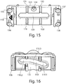
- the FIG. 15 shows a wing attachment portion 118, which in both the arrangement according to the FIG. 14 as well as in the arrangement according to the FIG. 13 can be used.
- the wing attachment part 118 has a straight longitudinal slot 130, through which the control element 109 or 117 can project in order to engage the control element 110.
- the transverse guides 119, 120 are also visible.
- the transverse guides 131, 132 are designed so that between them a region 133 results, which is dovetail-shaped in cross-section.
- the region 133 in turn constitutes a transverse guide for the guide parts 108, 115.
- the dovetail-shaped configuration makes it possible to prevent tilting of the guide parts 108, 115 relative to the wing fastening part 118.
- a fastening opening 134 is provided in the region of the transverse guide 133. Through the mounting hole 134, a screw can be screwed into the casement. Further attachment openings 135 - 138 can also be seen.
- FIG. 16 shows a view of the guide member 108.
- the control element 110 has two sections 110.1, 110.2, which are aligned differently from the Falz donors.
- the section 110.1 has a greater angle to the fold circumferential direction or longitudinal direction of the wing part 108 than the section 110.2.
- the Transverse guide 133 of the wing attachment part 118 is guided in the area 135 of the guide part 108.
- the Figure 17a shows a view from below of the guide member 108 and the wing attachment member 118.
- the guide member 108 is in a right extreme position corresponding to a closed position of the wing.
- the view of the wing attachment portion 118 according to the FIG. 17b indicates that the control element 109 is located in the section 110.2 of the control element 110.
- the control 109 is displaced in Falz donorsscardi, ie according to the FIG. 17b displaced upward, so enters the control element 109 in the area 110.1 of the control 110, as shown in the FIG. 18b is shown.
- This results in that the guide member 108 is displaced to the left, as in the FIG. 18a you can see.
- This position corresponds to a sliding position.
- the sliding leaf 3 can be moved in this position relative to the fixed enclosure 4. In this position, the sliding sash 3 is completely turned off from the fixed enclosure. If, on the other hand, the control element 109 is located in the section 110.3, the sliding leaf 3 is in a partially parked position, in which the slit ventilation part 10 and slit ventilation counterpart 20 can cooperate, in particular blocking the sliding sash 3 in a slit ventilation position.
Landscapes
- Engineering & Computer Science (AREA)
- Mechanical Engineering (AREA)
- Specific Sealing Or Ventilating Devices For Doors And Windows (AREA)
Claims (13)
- Porte coulissante (1) ou fenêtre coulissante, avec un encadrement fixe (4) et avec un vantail coulissant (3) qui, au moyen d'un système de déplacement (100), peut être déplacé transversalement au plan principal de la fenêtre coulissante ou de la porte coulissante (1) par rapport à l'encadrement fixe (4), et avec un système d'aération par entrebâillement comprenant un élément (10) d'aération par entrebâillement, sachant que le système de déplacement (100) peut être manoeuvré au moyen d'une poignée d'actionnement (7), sachant qu'une position totalement écartée du vantail coulissant (3), dans laquelle il peut être coulissé librement par rapport à l'encadrement fixe (4) dans la direction d'ouverture par coulissement de la porte coulissante (1) ou de la fenêtre coulissante, est associée à une première position de la poignée d'actionnement, qu'une position fermée du vantail coulissant (3), dans laquelle le vantail coulissant (3) est pressé contre l'encadrement fixe (4), est associée à une deuxième position de la poignée d'actionnement, et qu'une position intermédiaire entre la position totalement écartée et la position fermée est associée à une troisième position de la poignée d'actionnement, caractérisée en ce que, dans la troisième position de la poignée d'actionnement, le vantail coulissant (3) peut être coulissé dans la direction d'ouverture par coulissement de la porte coulissante (1) ou de la fenêtre coulissante par rapport à l'encadrement fixe (4), jusqu'à ce qu'un élément (10) d'aération par entrebâillement bute contre un élément complémentaire d'aération par entrebâillement et empêche le vantail coulissant (3) de coulisser davantage dans la direction d'ouverture par coulissement.
- Porte coulissante ou fenêtre coulissante selon la revendication 1, caractérisée en ce que l'élément (10) d'aération par entrebâillement présente une partie de fixation (11) pour la fixation de l'élément (10) d'aération par entrebâillement sur le vantail coulissant (3) ou l'encadrement fixe (4) et une partie (12) de butée ou d'engagement pour la coopération avec un élément complémentaire (20) d'aération par entrebâillement, sachant que la partie (12) de butée ou d'engagement peut être déplacée à l'encontre d'une force de rappel par rapport à la partie de fixation (11), par le fait que l'élément (10) d'aération par entrebâillement est réalisé au moins pour partie en un matériau élastique.
- Porte coulissante ou fenêtre coulissante selon la revendication 2, caractérisée en ce que l'élément (10) d'aération par entrebâillement est réalisé au moins pour partie en acier à ressorts.
- Porte coulissante ou fenêtre coulissante selon l'une des revendications précédentes, caractérisée en ce que l'élément (10) d'aération par entrebâillement présente un ergot (13) s'étendant transversalement au plan principal.
- Porte coulissante ou fenêtre coulissante selon la revendication 4, caractérisée en ce que l'ergot (13) est réalisé en matériau flexible ou présente un revêtement en matériau flexible.
- Porte coulissante ou fenêtre coulissante selon l'une des revendications précédentes, caractérisée en ce qu'il est prévu un élément complémentaire (20) d'aération par entrebâillement pouvant être fixé sur l'encadrement fixe (4) ou sur le vantail coulissant (3), élément qui présente une butée (21) et/ou un évidement (22) pour la partie (12) de butée ou d'engagement de l'élément (10) d'aération par entrebâillement.
- Porte coulissante ou fenêtre coulissante selon la revendication 6, caractérisée en ce que l'élément complémentaire (20) d'aération par entrebâillement présente un logement (23) pour l'ergot (13) de l'élément (10) d'aération par entrebâillement.
- Porte coulissante ou fenêtre coulissante selon l'une des revendications précédentes 6 ou 7, caractérisée en ce que l'élément complémentaire (20) d'aération par entrebâillement présente un biais d'entrée (24) menant à la butée (21) et/ou à l'évidement (22).
- Porte coulissante ou fenêtre coulissante selon l'une des revendications précédentes 6 à 8, caractérisée en ce que l'élément complémentaire (20) d'aération par entrebâillement présente un biais de déviation (25) pour l'ergot (13), biais qui est situé après, considéré dans la direction d'ouverture par coulissement, le logement (23) pour l'ergot (13).
- Porte coulissante ou fenêtre coulissante selon l'une des revendications précédentes 6 à 9, caractérisée en ce que l'élément complémentaire (20) d'aération par entrebâillement présente, avant la butée (21) et/ou l'évidement (22) considéré dans la direction d'ouverture par coulissement, un biais d'entrée (26) pour la partie (12) de butée ou d'engagement.
- Porte coulissante ou fenêtre coulissante selon l'une des revendications précédentes, caractérisée en ce que le système d'aération par entrebâillement est disposé dans une région du vantail coulissant (3) qui est opposée à un interstice d'aération.
- Porte coulissante ou fenêtre coulissante selon l'une des revendications précédentes, caractérisée en ce que le vantail coulissant (3) présente une rainure en forme de C, sur laquelle est fixé l'élément (10) d'aération par entrebâillement.
- Porte coulissante ou fenêtre coulissante selon l'une des revendications précédentes, caractérisée en ce que l'encadrement fixe (4) présente une nervure de guidage (32), sur laquelle est disposé l'élément complémentaire (20) d'aération par entrebâillement.
Priority Applications (5)
| Application Number | Priority Date | Filing Date | Title |
|---|---|---|---|
| EP13192304.7A EP2871312B1 (fr) | 2013-11-11 | 2013-11-11 | Dispositif d'aération par entrebâillement pour porte ou fenêtre coulissante et porte ou fenêtre coulissante |
| PL13192304T PL2871312T3 (pl) | 2013-11-11 | 2013-11-11 | Układ wietrzenia szczelinowego dla drzwi przesuwnych lub okna przesuwnego i drzwi przesuwne lub okno przesuwne |
| DK13192304.7T DK2871312T3 (en) | 2013-11-11 | 2013-11-11 | Sliding ventilation device for sliding door or window and sliding door or window |
| ES13192304.7T ES2633163T3 (es) | 2013-11-11 | 2013-11-11 | Dispositivo de abertura de ventilación para una puerta o ventana corredera y puerta o ventana corredera |
| PCT/EP2014/073484 WO2015067540A1 (fr) | 2013-11-11 | 2014-10-31 | Porte coulissante ou fenêtre coulissante |
Applications Claiming Priority (1)
| Application Number | Priority Date | Filing Date | Title |
|---|---|---|---|
| EP13192304.7A EP2871312B1 (fr) | 2013-11-11 | 2013-11-11 | Dispositif d'aération par entrebâillement pour porte ou fenêtre coulissante et porte ou fenêtre coulissante |
Publications (2)
| Publication Number | Publication Date |
|---|---|
| EP2871312A1 EP2871312A1 (fr) | 2015-05-13 |
| EP2871312B1 true EP2871312B1 (fr) | 2017-04-12 |
Family
ID=49554128
Family Applications (1)
| Application Number | Title | Priority Date | Filing Date |
|---|---|---|---|
| EP13192304.7A Active EP2871312B1 (fr) | 2013-11-11 | 2013-11-11 | Dispositif d'aération par entrebâillement pour porte ou fenêtre coulissante et porte ou fenêtre coulissante |
Country Status (5)
| Country | Link |
|---|---|
| EP (1) | EP2871312B1 (fr) |
| DK (1) | DK2871312T3 (fr) |
| ES (1) | ES2633163T3 (fr) |
| PL (1) | PL2871312T3 (fr) |
| WO (1) | WO2015067540A1 (fr) |
Cited By (2)
| Publication number | Priority date | Publication date | Assignee | Title |
|---|---|---|---|---|
| WO2021149873A1 (fr) * | 2020-01-23 | 2021-07-29 | 주식회사 씨에스테크 | Ensemble fenêtre/porte ayant une fonction de ventilation et une fonction d'étanchéité horizontale |
| WO2023222379A1 (fr) * | 2022-05-17 | 2023-11-23 | Roto Frank Fenster- und Türtechnologie GmbH | Porte coulissante sans barrière comprenant un battant réglable transversalement |
Families Citing this family (2)
| Publication number | Priority date | Publication date | Assignee | Title |
|---|---|---|---|---|
| DE102022114632A1 (de) * | 2022-06-10 | 2023-12-21 | Roto Frank Fenster- und Türtechnologie GmbH | Beschlaganordnung zur Anordnung zwischen einem festen Rahmen und einem Flügel eines Fensters oder einer Tür sowie Fenster oder Tür mit einer derartigen Beschlaganordnung |
| EP4386163B1 (fr) * | 2022-12-14 | 2025-02-05 | Gretsch-Unitas GmbH Baubeschläge | Agencement de porte coulissante |
Family Cites Families (5)
| Publication number | Priority date | Publication date | Assignee | Title |
|---|---|---|---|---|
| DE2700598C2 (de) * | 1977-01-08 | 1985-08-08 | Carl Fuhr Gmbh & Co, 5628 Heiligenhaus | Schiebefenster |
| SE9000605L (sv) * | 1990-02-20 | 1991-08-21 | Luminator Ab | Positionsbroms foer skjutdoerrar |
| DE202005016773U1 (de) * | 2005-10-26 | 2006-01-05 | Steinbach & Vollmann Gmbh & Co. Kg | Vorrichtung zum lösbaren Halten einer Verschlußeinheit |
| KR100729222B1 (ko) | 2005-12-29 | 2007-06-19 | 이광석 | 미서기 창호 시스템의 개폐장치 및 개폐방법 |
| DE102006044157A1 (de) * | 2006-09-15 | 2008-03-27 | Hermann Francksen Nachf. Gmbh & Co. Kg | Vorrichtung zur verfahrbaren Anordnung einer Schiebetür |
-
2013
- 2013-11-11 ES ES13192304.7T patent/ES2633163T3/es active Active
- 2013-11-11 EP EP13192304.7A patent/EP2871312B1/fr active Active
- 2013-11-11 PL PL13192304T patent/PL2871312T3/pl unknown
- 2013-11-11 DK DK13192304.7T patent/DK2871312T3/en active
-
2014
- 2014-10-31 WO PCT/EP2014/073484 patent/WO2015067540A1/fr not_active Ceased
Non-Patent Citations (1)
| Title |
|---|
| None * |
Cited By (3)
| Publication number | Priority date | Publication date | Assignee | Title |
|---|---|---|---|---|
| WO2021149873A1 (fr) * | 2020-01-23 | 2021-07-29 | 주식회사 씨에스테크 | Ensemble fenêtre/porte ayant une fonction de ventilation et une fonction d'étanchéité horizontale |
| US12084911B2 (en) | 2020-01-23 | 2024-09-10 | Cs Tech Co., Ltd. | Windows and doors assembly having ventilation function and horizontal contact function |
| WO2023222379A1 (fr) * | 2022-05-17 | 2023-11-23 | Roto Frank Fenster- und Türtechnologie GmbH | Porte coulissante sans barrière comprenant un battant réglable transversalement |
Also Published As
| Publication number | Publication date |
|---|---|
| DK2871312T3 (en) | 2017-06-06 |
| ES2633163T3 (es) | 2017-09-19 |
| WO2015067540A1 (fr) | 2015-05-14 |
| EP2871312A1 (fr) | 2015-05-13 |
| PL2871312T3 (pl) | 2017-09-29 |
Similar Documents
| Publication | Publication Date | Title |
|---|---|---|
| EP2829679B1 (fr) | Ferrure pour l'appui d'un battant mobile contre une bordure fixe | |
| EP2746503B1 (fr) | Serrure de véhicule automobile | |
| EP3702562B1 (fr) | Ferrure de fixation ainsi qu'agencement de ferrure et agencement de cadre et de battant | |
| DE102011011113B4 (de) | Rahmensystem eines Partikelschutzgitters | |
| EP3417134B1 (fr) | Ensemble ferrure pour le raccordement d'un battant coulissant et basculant | |
| EP2474696B1 (fr) | Dispositif de traction d'un vantail de porte ou d'un battant de fenêtre sur le cadre | |
| DE202022100517U1 (de) | Profilanordnung eines Fensters oder einer Tür mit einem Flügelprofil, insbesondere einem Schiebeflügelprofil | |
| EP2871312B1 (fr) | Dispositif d'aération par entrebâillement pour porte ou fenêtre coulissante et porte ou fenêtre coulissante | |
| AT396387B (de) | Sektionaltor | |
| EP0249682A2 (fr) | Dispositif déflecteur pour vantail de portes, fenêtres ou similaires comprenant un système de sécurité contre la fermeture à l'état ouvert du vantail | |
| DE202016001162U1 (de) | Aushebeschutzeinrichtung für einen parallel verschiebbaren Flügel als Schiebekippflügel oder Schiebeflügel | |
| DE19951608A1 (de) | Schließfolgesteuerung mit vom Standflügel betätigter Sperreinrichtung | |
| EP0246431B1 (fr) | Dispositif déflecteur pour panneau basculant, en particulier panneau oscillo-battant ou battant coulissant et basculant, de fenêtres, portes ou similaires | |
| EP2772604A2 (fr) | Limiteur d'ouverture | |
| DE102014007841A1 (de) | Dachfenster sowie Verfahren zum Montieren eines Dachfensters | |
| DE102012213786B3 (de) | Verlagerungsanordnung zur Verlagerung eines Flügels eines Fensters, einer Tür oder dergleichen relativ zu einer festen Einfassung | |
| EP2597234A2 (fr) | Dispositif d'arrêt d'une porte, de préférence avec ferme-porte | |
| EP2511463B1 (fr) | Fenêtre, porte ou analogue pourvue d'un dispositif d'amortissement | |
| EP3428375B1 (fr) | Dispositif de protection pour doigt | |
| EP1498563B1 (fr) | Dispositif pour créer une fente d'aération | |
| DE3215452A1 (de) | Eckumlenkung fuer treibstangenbeschlaege von fenstern, tueren od. dgl. | |
| EP0554671A1 (fr) | Dispositif d'aération pour locaux | |
| DE2729394A1 (de) | Verriegelungseinrichtung fuer fenster, tueren o.dgl. | |
| EP4242412B1 (fr) | Joint d'étanchéité doté d'une baguette d'étanchéité mobile à l'aide d'un mécanisme de mise en mouvement, le mécanisme de mise en mouvement étant actionnable au moyen d'un actionneur au moins partiellement pivotant | |
| DE9216213U1 (de) | Schließplatte |
Legal Events
| Date | Code | Title | Description |
|---|---|---|---|
| PUAI | Public reference made under article 153(3) epc to a published international application that has entered the european phase |
Free format text: ORIGINAL CODE: 0009012 |
|
| 17P | Request for examination filed |
Effective date: 20131111 |
|
| AK | Designated contracting states |
Kind code of ref document: A1 Designated state(s): AL AT BE BG CH CY CZ DE DK EE ES FI FR GB GR HR HU IE IS IT LI LT LU LV MC MK MT NL NO PL PT RO RS SE SI SK SM TR |
|
| AX | Request for extension of the european patent |
Extension state: BA ME |
|
| R17P | Request for examination filed (corrected) |
Effective date: 20150819 |
|
| RBV | Designated contracting states (corrected) |
Designated state(s): AL AT BE BG CH CY CZ DE DK EE ES FI FR GB GR HR HU IE IS IT LI LT LU LV MC MK MT NL NO PL PT RO RS SE SI SK SM TR |
|
| GRAP | Despatch of communication of intention to grant a patent |
Free format text: ORIGINAL CODE: EPIDOSNIGR1 |
|
| INTG | Intention to grant announced |
Effective date: 20161031 |
|
| GRAS | Grant fee paid |
Free format text: ORIGINAL CODE: EPIDOSNIGR3 |
|
| GRAA | (expected) grant |
Free format text: ORIGINAL CODE: 0009210 |
|
| AK | Designated contracting states |
Kind code of ref document: B1 Designated state(s): AL AT BE BG CH CY CZ DE DK EE ES FI FR GB GR HR HU IE IS IT LI LT LU LV MC MK MT NL NO PL PT RO RS SE SI SK SM TR |
|
| REG | Reference to a national code |
Ref country code: RO Ref legal event code: EPE Ref country code: GB Ref legal event code: FG4D Free format text: NOT ENGLISH |
|
| REG | Reference to a national code |
Ref country code: CH Ref legal event code: EP |
|
| REG | Reference to a national code |
Ref country code: IE Ref legal event code: FG4D Free format text: LANGUAGE OF EP DOCUMENT: GERMAN |
|
| REG | Reference to a national code |
Ref country code: AT Ref legal event code: REF Ref document number: 884053 Country of ref document: AT Kind code of ref document: T Effective date: 20170515 |
|
| REG | Reference to a national code |
Ref country code: DE Ref legal event code: R096 Ref document number: 502013006925 Country of ref document: DE |
|
| REG | Reference to a national code |
Ref country code: DK Ref legal event code: T3 Effective date: 20170601 |
|
| REG | Reference to a national code |
Ref country code: SE Ref legal event code: TRGR |
|
| REG | Reference to a national code |
Ref country code: NL Ref legal event code: FP |
|
| REG | Reference to a national code |
Ref country code: LT Ref legal event code: MG4D |
|
| REG | Reference to a national code |
Ref country code: NO Ref legal event code: T2 Effective date: 20170412 |
|
| REG | Reference to a national code |
Ref country code: ES Ref legal event code: FG2A Ref document number: 2633163 Country of ref document: ES Kind code of ref document: T3 Effective date: 20170919 |
|
| PG25 | Lapsed in a contracting state [announced via postgrant information from national office to epo] |
Ref country code: GR Free format text: LAPSE BECAUSE OF FAILURE TO SUBMIT A TRANSLATION OF THE DESCRIPTION OR TO PAY THE FEE WITHIN THE PRESCRIBED TIME-LIMIT Effective date: 20170713 Ref country code: LT Free format text: LAPSE BECAUSE OF FAILURE TO SUBMIT A TRANSLATION OF THE DESCRIPTION OR TO PAY THE FEE WITHIN THE PRESCRIBED TIME-LIMIT Effective date: 20170412 Ref country code: FI Free format text: LAPSE BECAUSE OF FAILURE TO SUBMIT A TRANSLATION OF THE DESCRIPTION OR TO PAY THE FEE WITHIN THE PRESCRIBED TIME-LIMIT Effective date: 20170412 Ref country code: HR Free format text: LAPSE BECAUSE OF FAILURE TO SUBMIT A TRANSLATION OF THE DESCRIPTION OR TO PAY THE FEE WITHIN THE PRESCRIBED TIME-LIMIT Effective date: 20170412 |
|
| REG | Reference to a national code |
Ref country code: FR Ref legal event code: PLFP Year of fee payment: 5 |
|
| PG25 | Lapsed in a contracting state [announced via postgrant information from national office to epo] |
Ref country code: IS Free format text: LAPSE BECAUSE OF FAILURE TO SUBMIT A TRANSLATION OF THE DESCRIPTION OR TO PAY THE FEE WITHIN THE PRESCRIBED TIME-LIMIT Effective date: 20170812 Ref country code: RS Free format text: LAPSE BECAUSE OF FAILURE TO SUBMIT A TRANSLATION OF THE DESCRIPTION OR TO PAY THE FEE WITHIN THE PRESCRIBED TIME-LIMIT Effective date: 20170412 Ref country code: LV Free format text: LAPSE BECAUSE OF FAILURE TO SUBMIT A TRANSLATION OF THE DESCRIPTION OR TO PAY THE FEE WITHIN THE PRESCRIBED TIME-LIMIT Effective date: 20170412 Ref country code: BG Free format text: LAPSE BECAUSE OF FAILURE TO SUBMIT A TRANSLATION OF THE DESCRIPTION OR TO PAY THE FEE WITHIN THE PRESCRIBED TIME-LIMIT Effective date: 20170712 |
|
| REG | Reference to a national code |
Ref country code: DE Ref legal event code: R097 Ref document number: 502013006925 Country of ref document: DE |
|
| REG | Reference to a national code |
Ref country code: HU Ref legal event code: AG4A Ref document number: E034000 Country of ref document: HU |
|
| PG25 | Lapsed in a contracting state [announced via postgrant information from national office to epo] |
Ref country code: SK Free format text: LAPSE BECAUSE OF FAILURE TO SUBMIT A TRANSLATION OF THE DESCRIPTION OR TO PAY THE FEE WITHIN THE PRESCRIBED TIME-LIMIT Effective date: 20170412 Ref country code: CZ Free format text: LAPSE BECAUSE OF FAILURE TO SUBMIT A TRANSLATION OF THE DESCRIPTION OR TO PAY THE FEE WITHIN THE PRESCRIBED TIME-LIMIT Effective date: 20170412 Ref country code: EE Free format text: LAPSE BECAUSE OF FAILURE TO SUBMIT A TRANSLATION OF THE DESCRIPTION OR TO PAY THE FEE WITHIN THE PRESCRIBED TIME-LIMIT Effective date: 20170412 |
|
| PLBE | No opposition filed within time limit |
Free format text: ORIGINAL CODE: 0009261 |
|
| STAA | Information on the status of an ep patent application or granted ep patent |
Free format text: STATUS: NO OPPOSITION FILED WITHIN TIME LIMIT |
|
| PG25 | Lapsed in a contracting state [announced via postgrant information from national office to epo] |
Ref country code: SM Free format text: LAPSE BECAUSE OF FAILURE TO SUBMIT A TRANSLATION OF THE DESCRIPTION OR TO PAY THE FEE WITHIN THE PRESCRIBED TIME-LIMIT Effective date: 20170412 |
|
| 26N | No opposition filed |
Effective date: 20180115 |
|
| PG25 | Lapsed in a contracting state [announced via postgrant information from national office to epo] |
Ref country code: SI Free format text: LAPSE BECAUSE OF FAILURE TO SUBMIT A TRANSLATION OF THE DESCRIPTION OR TO PAY THE FEE WITHIN THE PRESCRIBED TIME-LIMIT Effective date: 20170412 |
|
| REG | Reference to a national code |
Ref country code: NO Ref legal event code: MMEP |
|
| PG25 | Lapsed in a contracting state [announced via postgrant information from national office to epo] |
Ref country code: MC Free format text: LAPSE BECAUSE OF FAILURE TO SUBMIT A TRANSLATION OF THE DESCRIPTION OR TO PAY THE FEE WITHIN THE PRESCRIBED TIME-LIMIT Effective date: 20170412 |
|
| REG | Reference to a national code |
Ref country code: NL Ref legal event code: MM Effective date: 20171201 |
|
| PG25 | Lapsed in a contracting state [announced via postgrant information from national office to epo] |
Ref country code: NO Free format text: LAPSE BECAUSE OF NON-PAYMENT OF DUE FEES Effective date: 20171130 Ref country code: LI Free format text: LAPSE BECAUSE OF NON-PAYMENT OF DUE FEES Effective date: 20171130 Ref country code: CH Free format text: LAPSE BECAUSE OF NON-PAYMENT OF DUE FEES Effective date: 20171130 |
|
| PG25 | Lapsed in a contracting state [announced via postgrant information from national office to epo] |
Ref country code: LU Free format text: LAPSE BECAUSE OF NON-PAYMENT OF DUE FEES Effective date: 20171111 Ref country code: HU Free format text: LAPSE BECAUSE OF NON-PAYMENT OF DUE FEES Effective date: 20171112 Ref country code: RO Free format text: LAPSE BECAUSE OF NON-PAYMENT OF DUE FEES Effective date: 20170412 |
|
| REG | Reference to a national code |
Ref country code: IE Ref legal event code: MM4A |
|
| PG25 | Lapsed in a contracting state [announced via postgrant information from national office to epo] |
Ref country code: MT Free format text: LAPSE BECAUSE OF FAILURE TO SUBMIT A TRANSLATION OF THE DESCRIPTION OR TO PAY THE FEE WITHIN THE PRESCRIBED TIME-LIMIT Effective date: 20170412 |
|
| PG25 | Lapsed in a contracting state [announced via postgrant information from national office to epo] |
Ref country code: NL Free format text: LAPSE BECAUSE OF NON-PAYMENT OF DUE FEES Effective date: 20171201 Ref country code: IT Free format text: LAPSE BECAUSE OF NON-PAYMENT OF DUE FEES Effective date: 20171111 Ref country code: IE Free format text: LAPSE BECAUSE OF NON-PAYMENT OF DUE FEES Effective date: 20171111 |
|
| PGFP | Annual fee paid to national office [announced via postgrant information from national office to epo] |
Ref country code: GB Payment date: 20181219 Year of fee payment: 6 Ref country code: SE Payment date: 20181126 Year of fee payment: 6 |
|
| PGFP | Annual fee paid to national office [announced via postgrant information from national office to epo] |
Ref country code: BE Payment date: 20181122 Year of fee payment: 6 Ref country code: ES Payment date: 20181218 Year of fee payment: 6 Ref country code: FR Payment date: 20181127 Year of fee payment: 6 Ref country code: GB Payment date: 20181126 Year of fee payment: 6 Ref country code: TR Payment date: 20181101 Year of fee payment: 6 |
|
| PG25 | Lapsed in a contracting state [announced via postgrant information from national office to epo] |
Ref country code: CY Free format text: LAPSE BECAUSE OF FAILURE TO SUBMIT A TRANSLATION OF THE DESCRIPTION OR TO PAY THE FEE WITHIN THE PRESCRIBED TIME-LIMIT Effective date: 20170412 |
|
| PG25 | Lapsed in a contracting state [announced via postgrant information from national office to epo] |
Ref country code: MK Free format text: LAPSE BECAUSE OF FAILURE TO SUBMIT A TRANSLATION OF THE DESCRIPTION OR TO PAY THE FEE WITHIN THE PRESCRIBED TIME-LIMIT Effective date: 20170412 |
|
| REG | Reference to a national code |
Ref country code: AT Ref legal event code: MM01 Ref document number: 884053 Country of ref document: AT Kind code of ref document: T Effective date: 20181111 |
|
| PG25 | Lapsed in a contracting state [announced via postgrant information from national office to epo] |
Ref country code: AT Free format text: LAPSE BECAUSE OF NON-PAYMENT OF DUE FEES Effective date: 20181111 |
|
| PG25 | Lapsed in a contracting state [announced via postgrant information from national office to epo] |
Ref country code: PT Free format text: LAPSE BECAUSE OF FAILURE TO SUBMIT A TRANSLATION OF THE DESCRIPTION OR TO PAY THE FEE WITHIN THE PRESCRIBED TIME-LIMIT Effective date: 20170412 |
|
| REG | Reference to a national code |
Ref country code: DK Ref legal event code: EBP Effective date: 20191130 |
|
| REG | Reference to a national code |
Ref country code: SE Ref legal event code: EUG |
|
| PG25 | Lapsed in a contracting state [announced via postgrant information from national office to epo] |
Ref country code: AL Free format text: LAPSE BECAUSE OF FAILURE TO SUBMIT A TRANSLATION OF THE DESCRIPTION OR TO PAY THE FEE WITHIN THE PRESCRIBED TIME-LIMIT Effective date: 20170412 |
|
| REG | Reference to a national code |
Ref country code: BE Ref legal event code: MM Effective date: 20191130 |
|
| PG25 | Lapsed in a contracting state [announced via postgrant information from national office to epo] |
Ref country code: SE Free format text: LAPSE BECAUSE OF NON-PAYMENT OF DUE FEES Effective date: 20191112 |
|
| GBPC | Gb: european patent ceased through non-payment of renewal fee |
Effective date: 20191111 |
|
| PG25 | Lapsed in a contracting state [announced via postgrant information from national office to epo] |
Ref country code: FR Free format text: LAPSE BECAUSE OF NON-PAYMENT OF DUE FEES Effective date: 20191130 Ref country code: DK Free format text: LAPSE BECAUSE OF NON-PAYMENT OF DUE FEES Effective date: 20191130 Ref country code: GB Free format text: LAPSE BECAUSE OF NON-PAYMENT OF DUE FEES Effective date: 20191111 |
|
| PG25 | Lapsed in a contracting state [announced via postgrant information from national office to epo] |
Ref country code: BE Free format text: LAPSE BECAUSE OF NON-PAYMENT OF DUE FEES Effective date: 20191130 |
|
| REG | Reference to a national code |
Ref country code: ES Ref legal event code: FD2A Effective date: 20210527 |
|
| PG25 | Lapsed in a contracting state [announced via postgrant information from national office to epo] |
Ref country code: ES Free format text: LAPSE BECAUSE OF NON-PAYMENT OF DUE FEES Effective date: 20191112 |
|
| PG25 | Lapsed in a contracting state [announced via postgrant information from national office to epo] |
Ref country code: TR Free format text: LAPSE BECAUSE OF NON-PAYMENT OF DUE FEES Effective date: 20191111 |
|
| PGFP | Annual fee paid to national office [announced via postgrant information from national office to epo] |
Ref country code: DE Payment date: 20241119 Year of fee payment: 12 |
|
| PGFP | Annual fee paid to national office [announced via postgrant information from national office to epo] |
Ref country code: PL Payment date: 20241029 Year of fee payment: 12 |