EP1991814B1 - Dispositif pour distribuer et reguler un fluide caloporteur issu d'une source de chauffage et/ou de refroidissement - Google Patents
Dispositif pour distribuer et reguler un fluide caloporteur issu d'une source de chauffage et/ou de refroidissement Download PDFInfo
- Publication number
- EP1991814B1 EP1991814B1 EP07722974.8A EP07722974A EP1991814B1 EP 1991814 B1 EP1991814 B1 EP 1991814B1 EP 07722974 A EP07722974 A EP 07722974A EP 1991814 B1 EP1991814 B1 EP 1991814B1
- Authority
- EP
- European Patent Office
- Prior art keywords
- heating
- return
- supply
- space
- pumps
- Prior art date
- Legal status (The legal status is an assumption and is not a legal conclusion. Google has not performed a legal analysis and makes no representation as to the accuracy of the status listed.)
- Active
Links
Images
Classifications
-
- F—MECHANICAL ENGINEERING; LIGHTING; HEATING; WEAPONS; BLASTING
- F24—HEATING; RANGES; VENTILATING
- F24D—DOMESTIC- OR SPACE-HEATING SYSTEMS, e.g. CENTRAL HEATING SYSTEMS; DOMESTIC HOT-WATER SUPPLY SYSTEMS; ELEMENTS OR COMPONENTS THEREFOR
- F24D3/00—Hot-water central heating systems
- F24D3/10—Feed-line arrangements, e.g. providing for heat-accumulator tanks, expansion tanks ; Hydraulic components of a central heating system
- F24D3/1058—Feed-line arrangements, e.g. providing for heat-accumulator tanks, expansion tanks ; Hydraulic components of a central heating system disposition of pipes and pipe connections
- F24D3/1066—Distributors for heating liquids
-
- F—MECHANICAL ENGINEERING; LIGHTING; HEATING; WEAPONS; BLASTING
- F24—HEATING; RANGES; VENTILATING
- F24D—DOMESTIC- OR SPACE-HEATING SYSTEMS, e.g. CENTRAL HEATING SYSTEMS; DOMESTIC HOT-WATER SUPPLY SYSTEMS; ELEMENTS OR COMPONENTS THEREFOR
- F24D3/00—Hot-water central heating systems
- F24D3/10—Feed-line arrangements, e.g. providing for heat-accumulator tanks, expansion tanks ; Hydraulic components of a central heating system
- F24D3/1058—Feed-line arrangements, e.g. providing for heat-accumulator tanks, expansion tanks ; Hydraulic components of a central heating system disposition of pipes and pipe connections
- F24D3/1066—Distributors for heating liquids
- F24D3/1075—Built up from modules
-
- F—MECHANICAL ENGINEERING; LIGHTING; HEATING; WEAPONS; BLASTING
- F24—HEATING; RANGES; VENTILATING
- F24D—DOMESTIC- OR SPACE-HEATING SYSTEMS, e.g. CENTRAL HEATING SYSTEMS; DOMESTIC HOT-WATER SUPPLY SYSTEMS; ELEMENTS OR COMPONENTS THEREFOR
- F24D3/00—Hot-water central heating systems
- F24D3/10—Feed-line arrangements, e.g. providing for heat-accumulator tanks, expansion tanks ; Hydraulic components of a central heating system
- F24D3/1091—Mixing cylinders
Definitions
- the invention relates to a device for distributing and controlling a coming from a heating and / or cooling source heat carrier in particular heating and / or cooling water, the heating and / or cooling bodies and / or surfaces is supplied in rooms of a building, with the features in that the device has an elongate housing which is separated in the longitudinal direction by a dividing wall into a longitudinally arranged feed space and into a return space arranged parallel thereto, that the flow of the heating and / or cooling source opens into the feed space from which the heats of the heating - and / or heat sink and / or surfaces branch off, that the returns of the heating and / or cooling body and / or surfaces open into the return space from which the return of the heating and / or cooling source emanates that in the Vor- and / or recirculation of the heating and / or cooling body and / or surfaces each a regulated decentralized pump is arranged.
- a distribution apparatus to which a plurality of circuits of a central heating system are connected.
- the device has an elongated housing whose interior has a flow chamber and a return chamber to which the headers and returns of the radiator and boiler are connected. Pumps are interposed in the supply and return lines of the radiators and boilers.
- the construction and connection of such a distribution device including the pump external to the device require a considerable amount of work.
- the DE 696 17 966 T2 discloses the preamble of independent claim 1.
- the object of the invention is to provide a device of the type mentioned, with low production and installation costs and with a small number of parts and small footprint for optimal supply of heating and / or Heatsink and / or surfaces of a building in particular an apartment or office provides.
- Such a compact manifold has all the essential parts such as: distribution pumps, central pump, especially mixing pump, check valves, sensors, controllers (master), switching power supply, an electronic assembly for multiple pumps, integrated motor controller possibly in an assembly (a board), filter, deaerator , modular design (function can be specified on site by simple conversion), expandable by simple addition of other distributors, little need for space.
- distribution pumps central pump, especially mixing pump, check valves, sensors, controllers (master), switching power supply
- an electronic assembly for multiple pumps possibly in an assembly (a board), filter, deaerator , modular design (function can be specified on site by simple conversion), expandable by simple addition of other distributors, little need for space.
- the installation effort is significantly reduced, the number of components small, mass production and the use of low-cost materials possible and the line losses are low in both the electrical and in the hydraulic lines.
- the compact, highly integrated design enables simple installation with low cable and wiring costs.
- a minimum water circulation is guaranteed and usually check valves are dispensable.
- the central pump can be regulated as required and a simple volume flow control over speed is possible.
- optimal accessibility for the service is given, especially if the device is located outside a home or office.
- a safe flow direction is achieved when check valves are arranged in the return runs of the heating and / or cooling bodies and / or surfaces.
- a check valve can also be arranged in the return of the heating and / or cooling source.
- An embodiment with a particularly favorable thermal control is created when the two rooms are connected to each other directly via a passage in particular as a mixing space for the admixture of cooler heat transfer medium from the return space in the flow chamber.
- a central or mixing pump is arranged, which promotes the originating from the flow of the heating and / or cooling source heat transfer, so that a very accurate control with low energy consumption is possible.
- the central or mixing pump convey the heat transfer medium into the mixing region between the return space and the supply space, in particular via an internal channel arranged in the device.
- a valve is arranged, with which the flow of the heating and / or cooling source can be regulated.
- a structurally particularly simple modular design is achieved when the device is divided into two or more sub-areas, each sub-area a flow space, a return space, connections for the supply and return lines to the heating and / or heat sink and / or surfaces and in particular having an internal channel to the mixing area.
- the device is modularly divided into two or more subregions, wherein at a portion of flow and return of the heating and / or cooling source is connected.
- Such a modular design allows for easy removal and conversion on site. If space is limited, additional distributors can be used.
- the device can be used as a distributor, as a hydraulic switch (s) and / or as an admixing pump (s).
- an electrical component with electrical connections and electronic components for regulating the pumps is arranged in or on the device.
- temperature and / or pressure sensors which are connected to the electrical component, can be arranged in and / or on the device.
- a device for distributing and regulating is provided for each housing or office unit. It is also of great advantage if the secondary circuits connected to the supply chamber are each connected to one, two or more heating and / or cooling bodies and / or surfaces of a room.
- At least one device for energy-specific heat quantity detection is arranged, so that additional devices, in particular thermostatic valves on the radiators, are not required for this purpose.
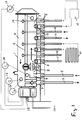
- Fig. 1 illustrated embodiment has an elongated housing 1, which is separated in the longitudinal direction by a partition wall 2 in a longitudinally arranged flow chamber (distribution chamber) 3 and in a return space 4 arranged parallel thereto. Both spaces 3, 4 may extend over the entire length of the housing 1.
- the flow chamber 3 is made shorter to provide space for a flow 5 and a return 6 a primary circuit in which a heat source, in particular a boiler and / or a cooling source.
- the flow 5 is connected via a plug connection 7 and a filter 8 arranged in a space 8 with the space 8, from which passes through a passage 10 of the incoming from the heating or cooling source heat carrier to the flow chamber 3.
- the passage 10 may also be arranged a valve.
- at least one breather may be arranged on the upper side of the housing.
- the supply lines go from 11, leading to radiators and / or heat sinks or heating and / or cooling surfaces H.
- the heat transfer medium in each case returns via return lines 12, which open into the return space 4.
- the feed lines 11 and the return lines 12 are in turn connected via connectors 7 to the device or the housing 1.
- a decentralized distributor pump 13 is arranged in each case, which sucks the heat transfer medium from the supply chamber 3 and conveys into the supply line.
- each leading to the heating and / or heat sink or surface H secondary circuit on a decentralized pump 13 so that thermostatic valves on the heat exchangers or the heating and / or cooling bodies or surfaces H are not required, but these decentralized Pumps bring the required due to their regulation Quantity of the heat carrier to the respective heating and / or cooling body or surface H.
- check valves 15 are arranged, which ensure that the heat carrier does not flow back into the return lines, but from the return space in the return line 6 of the primary circuit for heating or Cooling source passes.
- an electrical box 15 is fixed with electrical or electronic components and a power supply via electrical connections.
- the entire device is regulated with its individual parts, in particular the distributor pumps 13.
- a pressure and / or flow sensor 16 and three temperature sensors 17, 18 and 19 are arranged in the chamber 8 in the supply space 3 and in the return space 4.
- the distributor pumps 13 are controlled.
- further temperature sensors can be arranged in the secondary circuits.
- a pressure differential measuring device not shown, can be arranged between the flow 5 and the return 6, arranged.
- the medium or the heat transfer medium flows from the primary circuit 5, 6 in the flow chamber 8 of the manifold and from there via the passage 10 and a valve in the flow chamber 3. From there, the secondary circuits 11, 12 flows through the medium whose distributor pumps 13 are in operation. Thereafter, the medium enters the return chamber 4 and flows from there back into the primary circuit. Due to the check valves at the end of the return lines 12 backflow and thermal circulation are prevented.
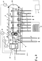
- the embodiment according to Fig. 2 is different from the after Fig. 1 essentially in that the supply space 3 are connected to the return space 4 with each other via a passage 20, which in the embodiment at one end of the interior of the device is arranged. Alternatively, this passage can also be provided elsewhere. Due to this connection of the two spaces, there is a partial mixing of the heat carrier or medium of both chambers 3, 4.
- This passage 20 is given an additional admixing function, due to a channel 21 opening into the passage area, which communicates with the flow 5 via the chamber 8 connected is.
- the heat transfer medium of the flow 5 of the primary circuit thus does not reach as in the embodiment Fig. 1 via the passage 10 in the flow chamber 3, but via the longitudinal channel 21 to the passage 20, which forms a mixing chamber there. This ensures that only as much heated or cooled liquid enters the supply lines 11, as is required in each case, that is, the decentralized distribution pumps 13 do not promote the medium of the supply line 5 unmixed in the supply lines 11, but in a mixed form.
- a central pump as mixing pump 22 which ensures how much medium or heat transfer medium passes through the channel 21 to the passage 20 and to the local mixing space.
- This pump 22 is in turn regulated by the electronics in the box 15, in particular using the arranged sensors.
- the medium flows from the supply chamber 8 through the secondary circuits into the return chamber 4 of the distributor.
- a flow through the primary circuit 5, 6 does not take place as long as the mixing pump 22 is turned off.
- After switching on the mixing pump 22 from the primary circuit to the secondary circuit only as much medium is supplied until, for example, a predetermined mixing temperature is reached. This is particularly interesting in combined systems such as radiators plus surface heating systems with different requirements regarding the flow temperature.
- a separate mixer can be omitted due to the mixing pump 22.
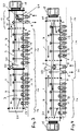
- the distributor device is in the embodiments according to 3 and 4 Modular modular design in which individual housing parts each form a manifold portion 1a with flow lines 11 and remindlaut effet 12, wherein two or more of these manifold areas are attached to each other.
- one distribution area is used per apartment, per office or per dwelling area or office area.
- a distributor region 1a is closed by a closure part 1b and at the other end a connection region 1c is connected as a separate housing, so that the flow chamber 8, the connection to the flow chamber 3 and the connection to the return chamber 4 forms and to the further flow and return 6 of the primary circuit are connected.
- connection region 1c needs to be fastened with its housing only to the housing of the distributor region 1a, in particular screwed on in order to obtain a complete distributor device.
- the supplied via the pump 22 longitudinal channel 21 is connected to the longitudinal channel 21 of the in Fig. 3 Connected left second distribution area 1a, so that the second distribution area is supplied via the pump 22.
- the box 15 is fastened to the electrical and electronic components.
- FIG. 4 an embodiment shown in which on both sides of the terminal portion 1c a respective distributor region 1a is connected, each with a separate electrical or electronic box 15 at the respective free end, in particular attached to the closure member 1b, so that the secondary circuits of the one distributor region 1a different can be regulated with respect to the secondary circuits of the other distribution area 1a.
- connection area 1c two pumps are shown.
- the upper pump 22 promotes as Beimischpumpe in the channel 21 with the above function and the underlying pump 26 promotes the flow 5 directly into the flow chamber 3, so that the connection area 1c as well as the embodiment according to Fig. 1 as well as alternatively as the execution after Fig. 2 can work.
- the housings of the distributor device and in particular also of the distributor regions and the connection regions, are elongated. Instead, these housings can also have other shapes and in particular box-shaped, cubic or be circular disk-shaped. This does not change the design features and functions described so far.
- measuring devices are arranged in particular sensors for energy in particular heat quantity detection, which has been used by the respective consumer.
- 13 sensors may also be provided in the secondary circuits and in particular in the distributor pumps.
Landscapes
- Engineering & Computer Science (AREA)
- Physics & Mathematics (AREA)
- Thermal Sciences (AREA)
- Chemical & Material Sciences (AREA)
- Combustion & Propulsion (AREA)
- Mechanical Engineering (AREA)
- General Engineering & Computer Science (AREA)
- Cooling Or The Like Of Electrical Apparatus (AREA)
- Other Air-Conditioning Systems (AREA)
Claims (23)
- Dispositif pour distribuer et régler un fluide caloporteur issu d'une source de chauffage et/ou de refroidissement, en particulier de l'eau de chauffage et/ou de refroidissement, qui est acheminée à des corps et/ou des surfaces (H) de chauffage et/ou de refroidissement dans des espaces d'un bâtiment, comprenant les caractéristiques suivantes :- le dispositif présente un boîtier allongé (1) qui est séparé dans la direction longitudinale par une paroi de séparation (2) en un espace d'alimentation (3) disposé longitudinalement et un espace de retour (4) disposé parallèlement à celui-ci,- la section d'alimentation (5) de la source de chauffage et/ou de refroidissement débouche dans l'espace d'alimentation (3) depuis lequel partent les sections d'alimentation (11) des corps et/ou des surfaces (H) de chauffage et/ou de refroidissement,- les sections de retour (12) des corps et/ou des surfaces (H) de chauffage et/ou de refroidissement débouchent dans l'espace de retour (4) depuis lequel part la section de retour (6) de la source de chauffage et/ou de refroidissement,- dans les sections d'alimentation et/ou de retour (11, 12) des corps et/ou des surfaces (H) de chauffage et/ou de refroidissement est à chaque fois disposée une pompe régulée décentralisée (13),caractérisé en ce que les pompes décentralisées (13) sont disposées à l'intérieur du boîtier (1) du dispositif.
- Dispositif selon la revendication 1, caractérisé en ce que les pompes décentralisées (13) sont disposées au niveau du point de connexion des conduites d'alimentation et/ou de retour (11, 12) au boîtier (1).
- Dispositif selon la revendication 2, caractérisé en ce que les pompes décentralisées (13) sont disposées au début des conduites d'alimentation et/ou de retour (11, 12).
- Dispositif selon la revendication 2, caractérisé en ce que les pompes décentralisées (13) sont disposées- dans la région de la connexion par enfichage des conduites d'alimentation et/ou de retour (11, 12) au boîtier et/ou aux espaces (3, 4) .
- Dispositif selon la revendication 4, caractérisé en ce que les pompes décentralisées (13) sont disposées du côté de la connexion par enfichage (7) tourné vers l'espace d'alimentation, respectivement de retour (3, 4).
- Dispositif selon l'une quelconque des revendications précédentes, caractérisé en ce que les pompes décentralisées (13) sont disposées dans les conduites d'alimentation et/ou de retour (11, 12) .
- Dispositif selon l'une quelconque des revendications précédentes, caractérisé en ce que les pompes décentralisées (13) sont disposées sur ou à l'intérieur de la paroi de boîtier.
- Dispositif selon la revendication 5, caractérisé en ce que les pompes décentralisées (13) sont disposées au niveau de la paroi intérieure de la paroi de boîtier.
- Dispositif selon l'une quelconque des revendications précédentes, caractérisé en ce que des clapets antiretour sont disposés dans les sections de retour (12) des corps et/ou des surfaces (H) de chauffage et/ou de refroidissement.
- Dispositif selon l'une quelconque des revendications précédentes, caractérisé en ce qu'un clapet antiretour est disposé dans la section de retour (6) de la source de chauffage et/ou de refroidissement.
- Dispositif selon l'une quelconque des revendications précédentes, caractérisé en ce que pour ajouter en mélange un fluide caloporteur plus froid provenant de l'espace de retour (4) dans l'espace d'alimentation (3), les deux espaces (3, 4) sont connectés directement l'un à l'autre par le biais d'un passage (20), notamment sous forme d'espace de mélange.
- Dispositif selon l'une quelconque des' revendications précédentes, caractérisé en ce qu'à l'intérieur du dispositif est disposée une pompe centrale ou de mélange (22) qui refoule le fluide caloporteur issu de la section d'alimentation (5) de la source de chauffage et/ou de refroidissement.
- Dispositif selon la revendication 12, caractérisé en ce que la pompe centrale ou de mélange (22) refoule le fluide caloporteur dans la région de mélange (20) entre l'espace de retour (4) et l'espace d'alimentation (3), notamment par le biais d'un canal interne (21) disposé dans le dispositif.
- Dispositif selon l'une quelconque des revendications précédentes, caractérisé en ce qu'à l'intérieur du dispositif est disposée une soupape avec laquelle la section d'alimentation (5) de la source de chauffage et/ou de refroidissement peut être régulée.
- Dispositif selon l'une quelconque des revendications précédentes, caractérisé en ce qu'il est divisé à la manière d'un compartiment modulaire en deux ou plus de deux régions partielles (la), chaque région partielle (la) présentant un espace d'alimentation (3), un espace de retour (4), des raccords pour les conduites d'alimentation et de retour (11, 12) au corps et/ou aux surfaces (H) de chauffage et/ou de refroidissement et notamment un canal interne à la région de mélange (20).
- Dispositif selon l'une quelconque des revendications précédentes, caractérisé en ce qu'il est divisé à la manière d'un compartiment modulaire en deux ou plus de deux régions partielles (la), une section d'alimentation et de retour (5, 6) de la source de chauffage et/ou de refroidissement étant raccordée à une région partielle (1c).
- Dispositif selon l'une quelconque des revendications précédentes, caractérisé en ce que dans ou sur le dispositif est disposé un composant électrique (15) avec des raccords électriques et des pièces électroniques pour la régulation des pompes.
- Dispositif selon la revendication 17, caractérisé en ce que dans et/ou sur le dispositif sont disposés des capteurs de température et/ou de pression (16-19) qui sont connectés au composant électrique (15).
- Dispositif selon l'une quelconque des revendications précédentes, caractérisé en ce que pour chaque unité d'habitation ou de bureau est prévu un dispositif de distribution et de réglage.
- Dispositif selon l'une quelconque des revendications précédentes, caractérisé en ce que les circuits secondaires (11, 12) raccordés à l'espace d'alimentation (3) sont à chaque fois connectés à un, deux ou plusieurs corps et/ou surfaces (H) de chauffage et/ou de refroidissement d'un espace.
- Dispositif selon l'une quelconque des revendications précédentes, caractérisé en ce que les raccords des conduites (5, 6, 11, 12) conduisant au fluide caloporteur peuvent être détachés par des connexions enfichables (7).
- Dispositif selon l'une quelconque des revendications précédentes, caractérisé en ce qu'au moins un dispositif est prévu pour détecter la quantité de chaleur.
- Dispositif selon l'une quelconque des revendications précédentes, caractérisé en ce que les pompes décentralisées (13) peuvent être réglées séparément les unes des autres, en fonction des besoins au niveau des corps et/ou des surfaces (H) de chauffage et/de refroidissement.
Applications Claiming Priority (2)
| Application Number | Priority Date | Filing Date | Title |
|---|---|---|---|
| DE102006010562A DE102006010562A1 (de) | 2006-03-06 | 2006-03-06 | Vorrichtung zum Verteilen und Regeln eines von einer Heiz- und/oder Kühlquelle stammenden Wärmeträgers |
| PCT/EP2007/001721 WO2007101592A1 (fr) | 2006-03-06 | 2007-02-28 | Dispositif pour distribuer et reguler un fluide caloporteur issu d'une source de chauffage et/ou de refroidissement |
Publications (2)
| Publication Number | Publication Date |
|---|---|
| EP1991814A1 EP1991814A1 (fr) | 2008-11-19 |
| EP1991814B1 true EP1991814B1 (fr) | 2018-04-11 |
Family
ID=38110357
Family Applications (1)
| Application Number | Title | Priority Date | Filing Date |
|---|---|---|---|
| EP07722974.8A Active EP1991814B1 (fr) | 2006-03-06 | 2007-02-28 | Dispositif pour distribuer et reguler un fluide caloporteur issu d'une source de chauffage et/ou de refroidissement |
Country Status (5)
| Country | Link |
|---|---|
| US (1) | US20090020270A1 (fr) |
| EP (1) | EP1991814B1 (fr) |
| CN (1) | CN101371080B (fr) |
| DE (1) | DE102006010562A1 (fr) |
| WO (1) | WO2007101592A1 (fr) |
Families Citing this family (20)
| Publication number | Priority date | Publication date | Assignee | Title |
|---|---|---|---|---|
| WO2009130724A1 (fr) * | 2008-04-23 | 2009-10-29 | I.V.A.R. S.P.A. | Dispositif hydraulique pour alimenter et commander un courant d'eau vers des utilisateurs |
| DE202009001056U1 (de) * | 2009-01-29 | 2010-06-24 | Comfort-Sinusverteiler Gmbh | Heizkreisverteiler |
| WO2011017841A1 (fr) * | 2009-08-13 | 2011-02-17 | Huo Weimin | Système de chauffage central à eau chaude pour étages multiples commandé à chaque étage |
| DE112010004272A5 (de) * | 2009-11-04 | 2013-04-25 | Invensor Gmbh | Kältestation als zentrale hydraulische schaltung und verteilung für sorptionsmaschinen |
| DE102009044566A1 (de) * | 2009-11-17 | 2011-05-19 | Domoteck Ltd. | Vorrichtung zum Temperieren eines in einem Heizkreislauf umgewälzten Wärmeübertragungsmediums |
| DE102009044674A1 (de) * | 2009-11-26 | 2011-06-01 | Domoteck Ltd. | Steuer- und Versorgungseinrichtung |
| ITMI20100077U1 (it) * | 2010-03-19 | 2011-09-20 | Ivar Spa | Dispositivo per la distribuzione di acqua di riscaldamento |
| EP2871422B2 (fr) * | 2013-11-07 | 2020-07-29 | Grundfos Holding A/S | Distributeur hydraulique pour un système de chauffage et/ou de refroidissement hydraulique |
| EP2871421B1 (fr) * | 2013-11-07 | 2017-04-12 | Grundfos Holding A/S | Distributeur hydraulique pour un système de chauffage et/ou de refroidissement hydraulique |
| DE202013105851U1 (de) * | 2013-12-20 | 2014-02-24 | Sinusverteiler Gmbh | Sammler- und Verteilereinheit für das Wärmeträgermedium einer Heizungsanlage mit mehreren Heizkesseln und mehreren Heizkreisen |
| EP3218652A1 (fr) * | 2014-11-12 | 2017-09-20 | Rea, David Patrick | Collecteur, bac tampon comprenant le collecteur et procédé pour faire fonctionner un système d'échange de chaleur |
| DK3067628T3 (en) * | 2015-03-12 | 2018-10-29 | Grundfos Holding As | Hydraulic valve |
| DE102015119801A1 (de) * | 2015-11-16 | 2017-05-18 | Simplex Armaturen & Systeme Gmbh | Sammelbalken und Heizkreisverteiler |
| DE102016002690A1 (de) * | 2016-03-08 | 2017-09-14 | Paw Gmbh & Co. Kg | Verfahren zur hydraulischen Entkopplung mehrerer, parallel geschalteter Fluidkreisläufe |
| ITUA20162523A1 (it) * | 2016-04-12 | 2017-10-12 | Mb Micheluzzi S R L | Sistema di purificazione con ispezione di pulizia, particolarmente per compensatore di impianto idraulico |
| CN106594843B (zh) * | 2016-12-30 | 2022-05-13 | 何宗衡 | 竖置式混能自平衡装置 |
| DE102018100422A1 (de) * | 2018-01-10 | 2019-07-11 | Viessmann Werke Gmbh & Co Kg | Anschluss-Set |
| JP7052392B2 (ja) * | 2018-02-09 | 2022-04-12 | 京セラドキュメントソリューションズ株式会社 | 画像形成装置 |
| CN110043942B (zh) * | 2019-04-17 | 2021-04-13 | 张健 | 智能热源分配管理系统 |
| RU196611U1 (ru) * | 2019-12-02 | 2020-03-06 | Сергей Юрьевич Кириченко | Безнапорный коллектор двухплоскостной |
Family Cites Families (12)
| Publication number | Priority date | Publication date | Assignee | Title |
|---|---|---|---|---|
| DE3809412A1 (de) * | 1988-03-21 | 1989-10-12 | Kamo Waermetechnische Ges Br A | Verteiler fuer heizungsanlagen |
| DE4108910A1 (de) * | 1991-03-19 | 1992-10-22 | Oplaender Wilo Werk Gmbh | Vorrichtung zur versorgung einer fussbodenheizung |
| CN1086889A (zh) * | 1993-06-07 | 1994-05-18 | 张立仁 | 新型暖气炉 |
| WO1997008498A1 (fr) * | 1995-08-29 | 1997-03-06 | Monard (Research & Development) Limited | Collecteur permettant de relier les circuits d'un systeme de chauffage central |
| DE29900636U1 (de) * | 1999-01-18 | 1999-04-01 | Supellex Ag, Frauenfeld | Vorrichtung zum Verteilen und Mischen eines im geschlossenen Kreislauf umgewälzten Wärmeträgermediums |
| US6347748B1 (en) * | 2001-01-26 | 2002-02-19 | Water Works Radiant Technologies, Inc. | Plumbing assembly for hydronic heating system and method of installation |
| US6345770B1 (en) * | 2001-04-13 | 2002-02-12 | Thomas O. Simensen | Modular manifold |
| AT411190B (de) * | 2001-10-02 | 2003-10-27 | Zortea Rembert | Heizanlage und/oder kühlanlage mit mindestens einer wärmequelle |
| SM200100020B (it) * | 2001-10-15 | 2003-04-16 | R D Z S P A | Struttura di circuito idraulico, particolarmente per la distribuzione di acqua per riscaldamento o raffrescamento |
| ES2302951T3 (es) * | 2002-07-25 | 2008-08-01 | Risto Antero Ojala | Colector para sistemas de calefaccion central. |
| US7191789B2 (en) * | 2003-05-02 | 2007-03-20 | Inventive Development L.L.C. | Transition adaptor and component modules for hydronic heating |
| US7661441B2 (en) * | 2004-05-21 | 2010-02-16 | Simensen Thomas O | Multi-line fluid conduit modules |
-
2006
- 2006-03-06 DE DE102006010562A patent/DE102006010562A1/de not_active Withdrawn
-
2007
- 2007-02-28 WO PCT/EP2007/001721 patent/WO2007101592A1/fr not_active Ceased
- 2007-02-28 CN CN2007800022371A patent/CN101371080B/zh not_active Expired - Fee Related
- 2007-02-28 EP EP07722974.8A patent/EP1991814B1/fr active Active
- 2007-02-28 US US12/282,009 patent/US20090020270A1/en not_active Abandoned
Also Published As
| Publication number | Publication date |
|---|---|
| US20090020270A1 (en) | 2009-01-22 |
| WO2007101592A1 (fr) | 2007-09-13 |
| EP1991814A1 (fr) | 2008-11-19 |
| DE102006010562A1 (de) | 2007-09-13 |
| CN101371080A (zh) | 2009-02-18 |
| CN101371080B (zh) | 2011-04-20 |
Similar Documents
| Publication | Publication Date | Title |
|---|---|---|
| EP1991814B1 (fr) | Dispositif pour distribuer et reguler un fluide caloporteur issu d'une source de chauffage et/ou de refroidissement | |
| EP2871422B1 (fr) | Distributeur hydraulique pour un système de chauffage et/ou de refroidissement hydraulique | |
| EP2932161B1 (fr) | Installation de chauffage ou de refroidissement à plusieurs circuits dotée d'un accumulateur tampon et procédé pour faire fonctionner une installation de chauffage ou de refroidissement à plusieurs circuits dotée d'un accumulateur tampon | |
| EP3066395B1 (fr) | Distributeur hydraulique pour un système de chauffage et/ou de refroidissement hydraulique | |
| EP2871420B1 (fr) | Module de pompe de circulation pour un système de chauffage et/ou de refroidissement | |
| EP3747074B1 (fr) | Système de refroidissement conçu pour un empilement de pile à combustible | |
| CH623649A5 (fr) | ||
| DE19527830C2 (de) | Verfahren zum Betrieb einer Heizanlage und Heizanlage | |
| EP1441160B1 (fr) | Ensemble de clapets | |
| EP2014992A1 (fr) | Répartiteur d'installations de température | |
| AT526014A1 (de) | Verfahren zum Kühlen oder Heizen von Räumen | |
| EP1845313A1 (fr) | Appareil à accumulation de chaleur | |
| EP3367005B1 (fr) | Système de chauffage | |
| DE2451544A1 (de) | Waermepumpe | |
| DE19925010A1 (de) | Mehrfach-Dreiwege-Mischer | |
| DE10311532B4 (de) | Wärmeverteilermodul | |
| AT387092B (de) | Vorrichtung zum erwaermen eines waermetraegers fuer einen heizkoerperkreislauf und von brauchwasser mit hilfe eines heizmediums | |
| DE10253650B3 (de) | Verfahren zur Pufferung von Wärmepumpenleistung in einem Trinkwasserspeicher und Anlage zu dessen Durchführung | |
| EP4411254B1 (fr) | Système d'alimentation d'une pluralité d'unités de consommation placées dans un bâtiment en exergie | |
| DE3712878C1 (en) | Valve arrangement for a water-heating installation | |
| DE102023120129A1 (de) | Pufferspeicher, Heizungsanlage und Verfahren zu deren Betrieb | |
| EP4737807A1 (fr) | Appareil ménager pour un bâtiment, procédé de montage d'un appareil ménager et procédé de fonctionnement d'un appareil ménager | |
| DE102012011567A1 (de) | Heiz- und/oder Kühlanlage | |
| EP0753806B1 (fr) | Arrangement pour régulation de température d'un dispositif de chauffage | |
| DE69505310T2 (de) | Heizkessel, aus mehreren Räumen bestehend |
Legal Events
| Date | Code | Title | Description |
|---|---|---|---|
| PUAI | Public reference made under article 153(3) epc to a published international application that has entered the european phase |
Free format text: ORIGINAL CODE: 0009012 |
|
| 17P | Request for examination filed |
Effective date: 20080520 |
|
| AK | Designated contracting states |
Kind code of ref document: A1 Designated state(s): AT BE BG CH CY CZ DE DK EE ES FI FR GB GR HU IE IS IT LI LT LU LV MC NL PL PT RO SE SI SK TR |
|
| 17Q | First examination report despatched |
Effective date: 20090219 |
|
| DAX | Request for extension of the european patent (deleted) | ||
| STAA | Information on the status of an ep patent application or granted ep patent |
Free format text: STATUS: EXAMINATION IS IN PROGRESS |
|
| REG | Reference to a national code |
Ref country code: DE Ref legal event code: R079 Ref document number: 502007016144 Country of ref document: DE Free format text: PREVIOUS MAIN CLASS: F24D0003100000 Ipc: F24D0019100000 |
|
| RIC1 | Information provided on ipc code assigned before grant |
Ipc: F24D 3/10 20060101ALI20171011BHEP Ipc: F24D 19/10 20060101AFI20171011BHEP |
|
| GRAP | Despatch of communication of intention to grant a patent |
Free format text: ORIGINAL CODE: EPIDOSNIGR1 |
|
| STAA | Information on the status of an ep patent application or granted ep patent |
Free format text: STATUS: GRANT OF PATENT IS INTENDED |
|
| INTG | Intention to grant announced |
Effective date: 20171128 |
|
| RAP1 | Party data changed (applicant data changed or rights of an application transferred) |
Owner name: WILO SE |
|
| GRAS | Grant fee paid |
Free format text: ORIGINAL CODE: EPIDOSNIGR3 |
|
| GRAA | (expected) grant |
Free format text: ORIGINAL CODE: 0009210 |
|
| STAA | Information on the status of an ep patent application or granted ep patent |
Free format text: STATUS: THE PATENT HAS BEEN GRANTED |
|
| AK | Designated contracting states |
Kind code of ref document: B1 Designated state(s): AT BE BG CH CY CZ DE DK EE ES FI FR GB GR HU IE IS IT LI LT LU LV MC NL PL PT RO SE SI SK TR |
|
| REG | Reference to a national code |
Ref country code: GB Ref legal event code: FG4D Free format text: NOT ENGLISH |
|
| REG | Reference to a national code |
Ref country code: CH Ref legal event code: EP |
|
| REG | Reference to a national code |
Ref country code: AT Ref legal event code: REF Ref document number: 988454 Country of ref document: AT Kind code of ref document: T Effective date: 20180415 |
|
| REG | Reference to a national code |
Ref country code: IE Ref legal event code: FG4D Free format text: LANGUAGE OF EP DOCUMENT: GERMAN |
|
| REG | Reference to a national code |
Ref country code: DE Ref legal event code: R096 Ref document number: 502007016144 Country of ref document: DE |
|
| REG | Reference to a national code |
Ref country code: NL Ref legal event code: MP Effective date: 20180411 |
|
| REG | Reference to a national code |
Ref country code: LT Ref legal event code: MG4D |
|
| PG25 | Lapsed in a contracting state [announced via postgrant information from national office to epo] |
Ref country code: NL Free format text: LAPSE BECAUSE OF FAILURE TO SUBMIT A TRANSLATION OF THE DESCRIPTION OR TO PAY THE FEE WITHIN THE PRESCRIBED TIME-LIMIT Effective date: 20180411 |
|
| PG25 | Lapsed in a contracting state [announced via postgrant information from national office to epo] |
Ref country code: FI Free format text: LAPSE BECAUSE OF FAILURE TO SUBMIT A TRANSLATION OF THE DESCRIPTION OR TO PAY THE FEE WITHIN THE PRESCRIBED TIME-LIMIT Effective date: 20180411 Ref country code: LT Free format text: LAPSE BECAUSE OF FAILURE TO SUBMIT A TRANSLATION OF THE DESCRIPTION OR TO PAY THE FEE WITHIN THE PRESCRIBED TIME-LIMIT Effective date: 20180411 Ref country code: PL Free format text: LAPSE BECAUSE OF FAILURE TO SUBMIT A TRANSLATION OF THE DESCRIPTION OR TO PAY THE FEE WITHIN THE PRESCRIBED TIME-LIMIT Effective date: 20180411 Ref country code: ES Free format text: LAPSE BECAUSE OF FAILURE TO SUBMIT A TRANSLATION OF THE DESCRIPTION OR TO PAY THE FEE WITHIN THE PRESCRIBED TIME-LIMIT Effective date: 20180411 Ref country code: SE Free format text: LAPSE BECAUSE OF FAILURE TO SUBMIT A TRANSLATION OF THE DESCRIPTION OR TO PAY THE FEE WITHIN THE PRESCRIBED TIME-LIMIT Effective date: 20180411 Ref country code: BG Free format text: LAPSE BECAUSE OF FAILURE TO SUBMIT A TRANSLATION OF THE DESCRIPTION OR TO PAY THE FEE WITHIN THE PRESCRIBED TIME-LIMIT Effective date: 20180711 |
|
| PG25 | Lapsed in a contracting state [announced via postgrant information from national office to epo] |
Ref country code: LV Free format text: LAPSE BECAUSE OF FAILURE TO SUBMIT A TRANSLATION OF THE DESCRIPTION OR TO PAY THE FEE WITHIN THE PRESCRIBED TIME-LIMIT Effective date: 20180411 Ref country code: GR Free format text: LAPSE BECAUSE OF FAILURE TO SUBMIT A TRANSLATION OF THE DESCRIPTION OR TO PAY THE FEE WITHIN THE PRESCRIBED TIME-LIMIT Effective date: 20180712 |
|
| PG25 | Lapsed in a contracting state [announced via postgrant information from national office to epo] |
Ref country code: PT Free format text: LAPSE BECAUSE OF FAILURE TO SUBMIT A TRANSLATION OF THE DESCRIPTION OR TO PAY THE FEE WITHIN THE PRESCRIBED TIME-LIMIT Effective date: 20180813 |
|
| REG | Reference to a national code |
Ref country code: DE Ref legal event code: R097 Ref document number: 502007016144 Country of ref document: DE |
|
| PG25 | Lapsed in a contracting state [announced via postgrant information from national office to epo] |
Ref country code: DK Free format text: LAPSE BECAUSE OF FAILURE TO SUBMIT A TRANSLATION OF THE DESCRIPTION OR TO PAY THE FEE WITHIN THE PRESCRIBED TIME-LIMIT Effective date: 20180411 Ref country code: EE Free format text: LAPSE BECAUSE OF FAILURE TO SUBMIT A TRANSLATION OF THE DESCRIPTION OR TO PAY THE FEE WITHIN THE PRESCRIBED TIME-LIMIT Effective date: 20180411 Ref country code: SK Free format text: LAPSE BECAUSE OF FAILURE TO SUBMIT A TRANSLATION OF THE DESCRIPTION OR TO PAY THE FEE WITHIN THE PRESCRIBED TIME-LIMIT Effective date: 20180411 Ref country code: CZ Free format text: LAPSE BECAUSE OF FAILURE TO SUBMIT A TRANSLATION OF THE DESCRIPTION OR TO PAY THE FEE WITHIN THE PRESCRIBED TIME-LIMIT Effective date: 20180411 Ref country code: RO Free format text: LAPSE BECAUSE OF FAILURE TO SUBMIT A TRANSLATION OF THE DESCRIPTION OR TO PAY THE FEE WITHIN THE PRESCRIBED TIME-LIMIT Effective date: 20180411 |
|
| PLBE | No opposition filed within time limit |
Free format text: ORIGINAL CODE: 0009261 |
|
| STAA | Information on the status of an ep patent application or granted ep patent |
Free format text: STATUS: NO OPPOSITION FILED WITHIN TIME LIMIT |
|
| PG25 | Lapsed in a contracting state [announced via postgrant information from national office to epo] |
Ref country code: IT Free format text: LAPSE BECAUSE OF FAILURE TO SUBMIT A TRANSLATION OF THE DESCRIPTION OR TO PAY THE FEE WITHIN THE PRESCRIBED TIME-LIMIT Effective date: 20180411 |
|
| 26N | No opposition filed |
Effective date: 20190114 |
|
| PG25 | Lapsed in a contracting state [announced via postgrant information from national office to epo] |
Ref country code: SI Free format text: LAPSE BECAUSE OF FAILURE TO SUBMIT A TRANSLATION OF THE DESCRIPTION OR TO PAY THE FEE WITHIN THE PRESCRIBED TIME-LIMIT Effective date: 20180411 |
|
| REG | Reference to a national code |
Ref country code: CH Ref legal event code: PL |
|
| GBPC | Gb: european patent ceased through non-payment of renewal fee |
Effective date: 20190228 |
|
| PG25 | Lapsed in a contracting state [announced via postgrant information from national office to epo] |
Ref country code: LU Free format text: LAPSE BECAUSE OF NON-PAYMENT OF DUE FEES Effective date: 20190228 Ref country code: MC Free format text: LAPSE BECAUSE OF FAILURE TO SUBMIT A TRANSLATION OF THE DESCRIPTION OR TO PAY THE FEE WITHIN THE PRESCRIBED TIME-LIMIT Effective date: 20180411 |
|
| REG | Reference to a national code |
Ref country code: BE Ref legal event code: MM Effective date: 20190228 |
|
| REG | Reference to a national code |
Ref country code: IE Ref legal event code: MM4A |
|
| PG25 | Lapsed in a contracting state [announced via postgrant information from national office to epo] |
Ref country code: CH Free format text: LAPSE BECAUSE OF NON-PAYMENT OF DUE FEES Effective date: 20190228 Ref country code: LI Free format text: LAPSE BECAUSE OF NON-PAYMENT OF DUE FEES Effective date: 20190228 |
|
| PG25 | Lapsed in a contracting state [announced via postgrant information from national office to epo] |
Ref country code: GB Free format text: LAPSE BECAUSE OF NON-PAYMENT OF DUE FEES Effective date: 20190228 Ref country code: IE Free format text: LAPSE BECAUSE OF NON-PAYMENT OF DUE FEES Effective date: 20190228 |
|
| PG25 | Lapsed in a contracting state [announced via postgrant information from national office to epo] |
Ref country code: BE Free format text: LAPSE BECAUSE OF NON-PAYMENT OF DUE FEES Effective date: 20190228 Ref country code: FR Free format text: LAPSE BECAUSE OF NON-PAYMENT OF DUE FEES Effective date: 20190228 |
|
| PG25 | Lapsed in a contracting state [announced via postgrant information from national office to epo] |
Ref country code: TR Free format text: LAPSE BECAUSE OF FAILURE TO SUBMIT A TRANSLATION OF THE DESCRIPTION OR TO PAY THE FEE WITHIN THE PRESCRIBED TIME-LIMIT Effective date: 20180411 |
|
| REG | Reference to a national code |
Ref country code: AT Ref legal event code: MM01 Ref document number: 988454 Country of ref document: AT Kind code of ref document: T Effective date: 20190228 |
|
| PG25 | Lapsed in a contracting state [announced via postgrant information from national office to epo] |
Ref country code: AT Free format text: LAPSE BECAUSE OF NON-PAYMENT OF DUE FEES Effective date: 20190228 |
|
| PG25 | Lapsed in a contracting state [announced via postgrant information from national office to epo] |
Ref country code: CY Free format text: LAPSE BECAUSE OF FAILURE TO SUBMIT A TRANSLATION OF THE DESCRIPTION OR TO PAY THE FEE WITHIN THE PRESCRIBED TIME-LIMIT Effective date: 20180411 |
|
| PG25 | Lapsed in a contracting state [announced via postgrant information from national office to epo] |
Ref country code: IS Free format text: LAPSE BECAUSE OF FAILURE TO SUBMIT A TRANSLATION OF THE DESCRIPTION OR TO PAY THE FEE WITHIN THE PRESCRIBED TIME-LIMIT Effective date: 20180811 |
|
| PG25 | Lapsed in a contracting state [announced via postgrant information from national office to epo] |
Ref country code: HU Free format text: LAPSE BECAUSE OF FAILURE TO SUBMIT A TRANSLATION OF THE DESCRIPTION OR TO PAY THE FEE WITHIN THE PRESCRIBED TIME-LIMIT; INVALID AB INITIO Effective date: 20070228 |
|
| P01 | Opt-out of the competence of the unified patent court (upc) registered |
Effective date: 20230615 |
|
| REG | Reference to a national code |
Ref country code: DE Ref legal event code: R084 Ref document number: 502007016144 Country of ref document: DE |
|
| PGFP | Annual fee paid to national office [announced via postgrant information from national office to epo] |
Ref country code: DE Payment date: 20250122 Year of fee payment: 19 |