EP2871731A1 - Entlüftungsanordnung für eine Schaltanlage - Google Patents
Entlüftungsanordnung für eine Schaltanlage Download PDFInfo
- Publication number
- EP2871731A1 EP2871731A1 EP20140189141 EP14189141A EP2871731A1 EP 2871731 A1 EP2871731 A1 EP 2871731A1 EP 20140189141 EP20140189141 EP 20140189141 EP 14189141 A EP14189141 A EP 14189141A EP 2871731 A1 EP2871731 A1 EP 2871731A1
- Authority
- EP
- European Patent Office
- Prior art keywords
- exhaust duct
- leg
- venting
- switchgear
- arrangement
- Prior art date
- Legal status (The legal status is an assumption and is not a legal conclusion. Google has not performed a legal analysis and makes no representation as to the accuracy of the status listed.)
- Granted
Links
Images
Classifications
-
- H—ELECTRICITY
- H02—GENERATION; CONVERSION OR DISTRIBUTION OF ELECTRIC POWER
- H02B—BOARDS, SUBSTATIONS OR SWITCHING ARRANGEMENTS FOR THE SUPPLY OR DISTRIBUTION OF ELECTRIC POWER
- H02B1/00—Frameworks, boards, panels, desks, casings; Details of substations or switching arrangements
- H02B1/56—Cooling; Ventilation
- H02B1/565—Cooling; Ventilation for cabinets
Definitions
- the invention relates to a venting arrangement for a switchgear.
- Ventilation arrangements for switchgear, especially for air-insulated medium voltage switchgear are known from the common prior art. From the DE 94 08 362 for example, a roof ventilation arrangement for electronic cabinets is known in which two fans are connected via an air box and a flap system with the electronics cabinet for forced ventilation.
- Object of the present invention is to provide a venting arrangement for a switchgear, which has a simple and inexpensive construction.
- Such a ventilation arrangement for a switchgear has a simple and inexpensive construction, because by the arrangement of at least a first exhaust duct for spontaneous venting and a further exhaust duct with a fan for forced ventilation and a corresponding shutter arrangement in a simple manner, there is a possibility between spontaneous vent and forced ventilation depending on external conditions, such as ambient temperature and the like to select.
- the at least one first exhaust duct and the further exhaust duct are arranged side by side, wherein the shutter assembly has at least one shutter which is rotatably mounted on a partition between the at least one first exhaust duct and the further exhaust duct to a pivot bearing and a first Leg, which extends from the pivot bearing in the first exhaust duct, and a second leg which extends from the pivot bearing in the further exhaust duct, wherein the first leg and the second leg are arranged substantially L-shaped to each other.
- essentially L-shaped in the sense of the present invention means that an angle is provided between the first leg and the second leg of the closure flap, which is preferably ⁇ 180 °, but> 60 °.
- the angle between the first leg and the second leg of the closure flap is between 100 ° and 140 °.
- the angle between the first leg and the second leg of the closure flap is 120 °.
- the first leg and the second leg of the flap have a weight ratio to each other such that at spontaneous venting by the lower weight forces of the lighter first leg to heavier second leg of the at least one first exhaust duct is open.
- the first and the second leg can be of different lengths, for example, depending on the size of an opening to be closed at least a first exhaust duct and further exhaust duct.
- the second leg may be heavier than the first leg, so that it is ensured that the closure flap rotates about its pivot bearing such that an inlet opening from the switchgear is open to at least one first exhaust duct.
- Lighter in the context of the present invention means that, in particular, the flow forces with forced venting with the fan switched on are sufficient to turn the closure flap around its bearing and to close the at least one first exhaust air channel by means of the first leg.
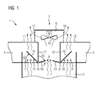
- FIG. 1 shows a schematic partial view of a switchgear 1, for example in the form of an air-insulated medium voltage switchgear, which has a switch panel 2 with figuratively not further running functional spaces, for example, for receiving a circuit breaker, for receiving busbars or cable outlets and current transformers, measuring devices.
- the switching field 2 is connected to a venting arrangement 3, which venting arrangement 3 in the exemplary embodiment comprises a first exhaust duct 4 and a second exhaust duct 5 and a further exhaust duct 6.
- the first exhaust duct 4 is connected via a first opening 7 to the panel 2
- the second exhaust duct 5 is connected via a second opening 8 to the panel 2
- the further exhaust duct 6 is connected via a further opening 9 with the panel 2.
- a fan 10 is arranged in another exhaust duct 6, a fan 10 is arranged.
- the first exhaust air duct 4 has a first exhaust air opening 11, the second exhaust air duct 5 has a second exhaust air opening 12, the further exhaust air duct 6 has further exhaust air openings 13 and 14.
- a first closure flap 15 is arranged on a first pivot bearing 16 on a first partition 17, which separates the first exhaust duct 4 from the further exhaust duct 6, and has a first leg 18 and a second leg 19, which form an angle of 120 ° in the exemplary embodiment ,
- the first leg 18 is provided for closing the first opening 7 when the fan 10 is running.
- the second leg 19 is provided for rotating the shutter 15 by the flow forces of the fan 10.
- a second closure flap 20 is attached to a second pivot bearing 21 on a second partition wall 22, which is arranged between the further exhaust duct 6 and the second exhaust duct 5, and also comprises a first leg 23 and a second leg 24, wherein the first leg 23 to Closing the second opening 8 is provided.
- the first opening 7 and the second opening 8, which connect the panel 2 to the first exhaust duct 4 and the second exhaust duct 5 are provided for spontaneous venting of the switchgear 1 by flow processes, which by the heated air, which within the switchgear. 1 ascends, be trained.
- the first leg 18 and the second leg 19 or the first leg 23 and the second leg 24 have weight ratios relative to one another based on the weight forces of the first leg 18 or 23 to the second leg 19 and 24 in spontaneous venting, the first opening 7 and the second opening 8 are opened, as in the FIG. 1 shown.
- the further opening 9, which connects the further exhaust duct 6 with the panel 2, must not be completely closed during spontaneous venting, but can also contribute to spontaneous venting via the further exhaust duct 6, as in the FIG. 1 shown.
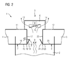
- first opening 7 and the second opening 8 are closed by the first leg 18 of the first shutter 15 and the first leg 23 of the second shutter 20, so that it is ensured that only a forced ventilation via the further exhaust duct 6th takes place with the fan 10 disposed therein and in particular no ambient air on the first opening 7 and the second opening 8 can get into the panel 2.
- FIGS. 1 and 2 The embodiment of FIGS. 1 and 2 is described with a first exhaust duct 4 and a second exhaust duct 5, which are each arranged next to the further exhaust duct 6, but it is obvious that optionally also a single first exhaust duct 4, which is arranged next to the further exhaust duct 6, with a corresponding shutter flap assembly is sufficient.
Landscapes
- Engineering & Computer Science (AREA)
- Power Engineering (AREA)
- Cooling Or The Like Of Electrical Apparatus (AREA)
- Patch Boards (AREA)
- Air-Flow Control Members (AREA)
Abstract
Description
- Die Erfindung betrifft eine Entlüftungsanordnung für eine Schaltanlage.
- Entlüftungsanordnungen für Schaltanlagen, insbesondere für luftisolierte Mittelspannungsschaltanlagen sind aus dem landläufigen Stand der Technik bekannt. Aus der
DE 94 08 362 ist beispielsweise eine Dachentlüftungsanordnung für Elektronikschränke bekannt, bei der zwei Lüfter über einen Luftkasten und ein Klappensystem mit dem Elektronikschrank zur zwangsweisen Entlüftung verbunden sind. - Aufgabe der vorliegenden Erfindung ist es, eine Entlüftungsanordnung für eine Schaltanlage auszubilden, welche über einen einfachen und kostengünstigen Aufbau verfügt.
- Erfindungsgemäß gelöst wird dies durch eine Entlüftungsanordnung für eine Schaltanlage mit mindestens einem ersten Abluftkanal zur spontanen Entlüftung der Schaltanlage sowie einem weiteren Abluftkanal, in welchem ein Lüfter zur zwangsweisen Entlüftung der Schaltanlage angeordnet ist, wobei eine Verschlussklappenanordnung derart ausgebildet ist, dass bei spontaner Entlüftung der mindestens eine erste Abluftkanal geöffnet ist und bei zwangsweiser Entlüftung der mindestens eine erste Abluftkanal geschlossen ist.
- Eine derartige Entlüftungsanordnung für eine Schaltanlage weist einen einfachen und kostengünstigen Aufbau auf, weil durch die Anordnung von mindestens einem ersten Abluftkanal zur spontanen Entlüftung sowie einem weiteren Abluftkanal mit einem Lüfter zur zwangsweisen Entlüftung und einer entsprechenden Verschlussklappenanordnung in einfacher Weise eine Möglichkeit besteht, zwischen spontaner Entlüftung und zwangsweiser Entlüftung je nach äußeren Gegebenheiten, beispielsweise Umgebungstemperatur und dergleichen, auszuwählen. So kann es beispielsweise bei einer niedrigen Umgebungstemperatur ausreichend sein, die Schaltanlage mittels der spontanen Entlüftung über den mindestens einen ersten Abluftkanal zu entlüften, wo hingegen bei beispielsweise steigender Umgebungstemperatur es unter Umständen notwendig sein kann, zu einer zwangsweisen Entlüftung mittels eines Lüftungssystems bzw. eines Lüfters umzuschalten, wobei in diesem Fall durch die Verschlussklappenanordnung und den geschlossenen mindestens einen ersten Abluftkanal gewährleistet ist, dass durch den mindestens einen ersten Abluftkanal keine Umgebungsluft in die Schaltanlage zurückströmen kann. Außerdem ist somit die Möglichkeit gegeben, dass bei Ausfall der zwangsweisen Entlüftung eine spontane Entlüftung wirksam wird.
- In einer vorteilhaften Ausgestaltung der Erfindung sind der mindestens eine erste Abluftkanal und der weitere Abluftkanal nebeneinander angeordnet, wobei die Verschlussklappenanordnung mindestens eine Verschlussklappe aufweist, welche an einer Trennwand zwischen dem mindestens einen ersten Abluftkanal und dem weiteren Abluftkanal an einem Drehlager drehbar angeordnet ist und einen ersten Schenkel, welcher sich vom Drehlager in den ersten Abluftkanal erstreckt, sowie einen zweiten Schenkel, welcher sich vom Drehlager in den weiteren Abluftkanal erstreckt, aufweist, wobei der erste Schenkel und der zweite Schenkel im Wesentlichen L-förmig zueinander angeordnet sind. Eine derartige Anordnung des mindestens einen ersten Abluftkanals neben dem weiteren Abluftkanal mit der im Wesentlichen L-förmig ausgebildeten Verschlussklappe der Verschlussklappenanordnung mit erstem und zweitem Schenkel führt zu einem einfachen und kostengünstigen Aufbau, weil durch den ersten Schenkel der mindestens eine erste Abluftkanal bei zwangsweiser Entlüftung verschließbar ist. Im Wesentlichen L-förmig im Sinne der vorliegenden Erfindung bedeutet dabei, dass zwischen dem ersten Schenkel und dem zweiten Schenkel der Verschlussklappe ein Winkel vorgesehen ist, welcher vorzugsweise <180°, aber >60° ist.
- In einer besonders bevorzugten Ausführungsform liegt der Winkel zwischen dem ersten Schenkel und dem zweiten Schenkel der Verschlussklappe zwischen 100° und 140°.
- In einer besonders bevorzugten Ausführungsform beträgt der Winkel zwischen dem ersten Schenkel und dem zweiten Schenkel der Verschlussklappe 120°. Durch eine derartige Wahl des Winkels zwischen dem ersten Schenkel und dem zweiten Schenkel ist es besonders einfach möglich, entweder den mindestens einen ersten Abluftkanal oder den einen weiteren Abluftkanal zu verschließen, wobei der jeweils andere Kanal geöffnet bleibt.
- In weiterer vorteilhafter Ausgestaltung der Erfindung weisen der erste Schenkel und der zweite Schenkel der Verschlussklappe ein Gewichtsverhältnis zueinander derart auf, dass bei spontaner Entlüftung durch die geringeren Gewichtskräfte des leichteren ersten Schenkels zu schwererem zweitem Schenkel der mindestens eine erste Abluftkanal geöffnet ist. Der erste und der zweite Schenkel können dabei unterschiedlich lang sein, beispielsweise je nach Größe einer zu verschließenden Öffnung von mindestens einem ersten Abluftkanal und weiterem Abluftkanal. Durch ihr Gewichtsverhältnis zueinander muss gewährleistet sein, dass sich durch die Gewichtskräfte zumindest eine spontane Entlüftung über den mindestens einen ersten Abluftkanal ausbildet, indem der erste Schenkel eine Eintrittsöffnung aus der Schaltanlage in den mindestens einen ersten Abluftkanal freigibt. Dabei kann der zweite Schenkel schwerer sein als der erste Schenkel, so dass gewährleistet ist, dass sich die Verschlussklappe um ihr Drehlager derartig dreht, dass eine Eintrittsöffnung aus der Schaltanlage zum mindestens einen ersten Abluftkanal geöffnet ist. Leichter im Sinne der vorliegenden Erfindung bedeutet dabei, dass insbesondere die Strömungskräfte bei zwangsweiser Entlüftung bei angeschaltetem Lüfter ausreichen, um die Verschlussklappe um ihr Lager zu drehen und mittels des ersten Schenkels den mindestens einen ersten Abluftkanal zu verschließen.
- Die Erfindung wird im Folgenden anhand der Zeichnung und eines Ausführungsbeispiels mit Bezug auf die beiliegenden Figuren näher erläutert. Es zeigen:
- Figur 1:
- eine teilweise schematische Ansicht einer erfindungsgemäßen Entlüftungsanordnung für eine Schaltanlage in einem ersten Zustand; und
- Figur 2:
- eine teilweise schematische Ansicht einer erfindungsgemäßen Entlüftungsanordnung für eine Schaltanlage in einem zweiten Zustand.
- Die
Figur 1 zeigt eine schematische teilweise Ansicht einer Schaltanlage 1, beispielsweise in Form einer luftisolierten Mittelspannungsschaltanlage, welche ein Schaltfeld 2 mit figürlich nicht weiter ausgeführten Funktionsräumen, beispielsweise zur Aufnahme eines Leistungsschalters, zur Aufnahme von Sammelschienen oder Kabelabgängen sowie Stromwandlern, Messgeräten etc. aufweist. Das Schaltfeld 2 ist mit einer Entlüftungsanordnung 3 verbunden, welche Entlüftungsanordnung 3 im Ausführungsbeispiel einen ersten Abluftkanal 4 sowie einen zweiten Abluftkanal 5 und einen weiteren Abluftkanal 6 umfasst. Der erste Abluftkanal 4 ist dabei über eine erste Öffnung 7 mit dem Schaltfeld 2 verbunden, der zweite Abluftkanal 5 ist über eine zweite Öffnung 8 mit dem Schaltfeld 2 verbunden, der weitere Abluftkanal 6 ist über eine weitere Öffnung 9 mit dem Schaltfeld 2 verbunden. Im weiteren Abluftkanal 6 ist ein Lüfter 10 angeordnet. Der erste Abluftkanal 4 weist eine erste Abluftöffnung 11 auf, der zweite Abluftkanal 5 weist eine zweite Abluftöffnung 12 auf, der weitere Abluftkanal 6 weist weitere Abluftöffnungen 13 und 14 auf. Eine erste Verschlussklappe 15 ist an einem ersten Drehlager 16 an einer ersten Trennwand 17, welche den ersten Abluftkanal 4 vom weiteren Abluftkanal 6 trennt, angeordnet und weist einen ersten Schenkel 18 sowie einen zweiten Schenkel 19 auf, welche im Ausführungsbeispiel einen Winkel von 120° einschließen. Der erste Schenkel 18 ist zum Verschließen der ersten Öffnung 7 vorgesehen, wenn der Lüfter 10 läuft. Der zweite Schenkel 19 ist zum Drehen der Verschlussklappe 15 durch die Strömungskräfte des Lüfters 10 vorgesehen. Eine zweite Verschlussklappe 20 ist an einem zweiten Drehlager 21 an einer zweiten Trennwand 22, welche zwischen dem weiteren Abluftkanal 6 und dem zweiten Abluftkanal 5 angeordnet ist, befestigt und umfasst ebenfalls einen ersten Schenkel 23 sowie einen zweiten Schenkel 24, wobei der erste Schenkel 23 zum Verschließen der zweiten Öffnung 8 vorgesehen ist. Die erste Öffnung 7 sowie die zweite Öffnung 8, welche das Schaltfeld 2 mit dem ersten Abluftkanal 4 bzw. dem zweiten Abluftkanal 5 verbinden, sind dabei zur spontanen Entlüftung der Schaltanlage 1 vorgesehen durch Strömungsvorgänge, welche durch die erwärmte Luft, welche innerhalb der Schaltanlage 1 aufsteigt, ausgebildet werden. Dazu weisen bei der ersten Verschlussklappe 15 und der zweiten Verschlussklappe 20 der erste Schenkel 18 und der zweite Schenkel 19 bzw. der erste Schenkel 23 und der zweite Schenkel 24 Gewichtsverhältnisse zueinander auf, dass anhand der Gewichtskräfte von erstem Schenkel 18 bzw. 23 zu zweitem Schenkel 19 bzw. 24 bei spontaner Entlüftung die erste Öffnung 7 bzw. die zweite Öffnung 8 geöffnet sind, wie in derFigur 1 dargestellt. Die weitere Öffnung 9, welche den weiteren Abluftkanal 6 mit dem Schaltfeld 2 verbindet, muss bei spontaner Entlüftung dabei nicht vollständig geschlossen sein, sondern kann ebenfalls zur spontanen Entlüftung über den weiteren Abluftkanal 6 beitragen, wie in derFigur 1 dargestellt. - Stellt sich nun an die Schaltanlage 1 die Anforderung, beispielsweise durch gestiegene Umgebungstemperaturen oder dergleichen, größere Mengen an wärmerer Abluft abzuführen, so wird dies über den Lüfter 10 im weiteren Abluftkanal 6 ermöglicht, in dem dieser durch eine entsprechende Steuerung angesteuert und angeschalten wird. In einem solchen Fall muss dann gewährleistet sein, dass über die erste Abluftöffnung 11 und die erste Öffnung 7 bzw. die zweite Abluftöffnung 12 und die zweite Öffnung 8 keine Umgebungsluft zurück ins Schaltfeld 2 geführt wird. Dazu müssen die erste Öffnung 7 bzw. die zweite Öffnung 8 bei zwangsweiser Entlüftung über den weiteren Abluftkanal 6 und den darin angeordneten Lüfter 10 verschlossen sein. Dies wird über die am ersten Drehlager 16 drehbar angeordnete erste Verschlussklappe 15 sowie über die am zweiten Drehlager 21 drehbar angeordnete zweite Verschlussklappe 20 derart gewährleistet, dass aufgrund der Gewichtskräfte von erstem Schenkel 18 bzw. erstem Schenkel 23 im Verhältnis zu zweitem Schenkel 19 bzw. zu zweitem Schenkel 24 in Zusammenhang mit den durch den Lüfter 10 erzeugten Strömungskräften im weiteren Abluftkanal 6 sich die erste Verschlussklappe 15 im Gegenuhrzeigersinn dreht, bis die erste Öffnung 7 verschlossen ist, und die zweite Verschlussklappe 20 sich im Uhrzeigersinn dreht, bis die zweite Öffnung 8 verschlossen ist, wie in der
Figur 2 dargestellt, in welcher die erste Öffnung 7 und die zweite Öffnung 8 durch den ersten Schenkel 18 der ersten Verschlussklappe 15 bzw. den ersten Schenkel 23 der zweiten Verschlussklappe 20 verschlossen sind, so dass gewährleistet ist, dass lediglich eine zwangsweise Entlüftung über den weiteren Abluftkanal 6 mit dem darin angeordneten Lüfter 10 stattfindet und insbesondere keine Umgebungsluft über die erste Öffnung 7 bzw. die zweite Öffnung 8 in das Schaltfeld 2 gelangen kann. - Das Ausführungsbeispiel der
Figuren 1 und2 ist dabei mit einem ersten Abluftkanal 4 und einem zweiten Abluftkanal 5, welche jeweils neben dem weiteren Abluftkanal 6 angeordnet sind, beschrieben, es ist aber offensichtlich, dass gegebenenfalls auch ein einziger erster Abluftkanal 4, welcher neben dem weiteren Abluftkanal 6 angeordnet ist, mit einer entsprechenden Verschlussklappenanordnung ausreicht. -
- 1
- Schaltanlage
- 2
- Schaltfeld
- 3
- Entlüftungsanordnung
- 4
- erster Abluftkanal
- 5
- zweiter Abluftkanal
- 6
- weiterer Abluftkanal
- 7
- erste Öffnung
- 8
- zweite Öffnung
- 9
- weitere Öffnung
- 10
- Lüfter
- 11
- erste Abluftöffnung
- 12
- zweite Abluftöffnung
- 13, 14
- weitere Abluftöffnungen
- 15
- erste Verschlussklappe
- 16
- erstes Drehlager
- 17
- erste Trennwand
- 18
- erster Schenkel
- 19
- zweiter Schenkel
- 20
- zweite Verschlussklappe
- 21
- zweites Drehlager
- 22
- zweite Trennwand
- 23
- erster Schenkel
- 24
- zweiter Schenkel
Claims (5)
- Entlüftungsanordnung (3) für eine Schaltanlage (1) mit mindestens einem ersten Abluftkanal (4, 5) zur spontanen Entlüftung der Schaltanlage (1) sowie einem weiteren Abluftkanal (6), in welchem ein Lüfter (10) zur zwangsweisen Entlüftung der Schaltanlage (1) angeordnet ist, wobei eine Verschlussklappenanordnung derart ausgebildet ist, dass bei spontaner Entlüftung der mindestens eine erste Abluftkanal (4, 5) geöffnet ist und bei zwangsweiser Entlüftung der mindestens eine erste Abluftkanal (4, 5) geschlossen ist.
- Entlüftungsanordnung (3) nach Anspruch 1,
dadurch gekennzeichnet, dass der mindestens eine erste Abluftkanal (4, 5) und der weitere Abluftkanal (6) nebeneinander angeordnet sind, wobei die Verschlussklappenanordnung mindestens eine Verschlussklappe (15, 20) aufweist, welche an einer Trennwand (17, 22) zwischen dem mindestens einen ersten Abluftkanal (4, 5) und dem weiteren Abluftkanal (6) an einem Drehlager (16, 21) drehbar angeordnet ist und einen ersten Schenkel (18, 23), welcher sich vom Drehlager (16, 21) in den ersten Abluftkanal (4, 5) erstreckt, sowie einen zweiten Schenkel (19, 24), welcher sich vom Drehlager (16, 21) in den weiteren Abluftkanal (6) erstreckt, aufweist, wobei der erste Schenkel (18, 23) und der zweite Schenkel (19, 24) im Wesentlichen L-förmig zueinander angeordnet sind. - Entlüftungsanordnung (3) nach Anspruch 2,
dadurch gekennzeichnet, dass der Winkel zwischen dem ersten Schenkel (18, 23) und dem zweiten Schenkel (19, 24) der Verschlussklappe (15, 20) zwischen 100° und 140° liegt. - Entlüftungsanordnung (3) nach Anspruch 2,
dadurch gekennzeichnet, dass der Winkel zwischen dem ersten Schenkel (18, 23) und dem zweiten Schenkel (19, 24) der Verschlussklappe (15, 20) 120° beträgt. - Entlüftungsanordnung (3) nach einem der Ansprüche 2 bis 4,
dadurch gekennzeichnet, dass der der erste Schenkel (18, 23) und der zweite Schenkel (19, 24) der Verschlussklappe (15, 20) ein Gewichtsverhältnis zueinander derart auf, dass bei spontaner Entlüftung durch die geringeren Gewichtskräfte des leichteren ersten Schenkels (18, 23) zu schwererem zweitem Schenkel (19, 24) der mindestens eine erste Abluftkanal (4, 5) geöffnet ist.
Applications Claiming Priority (1)
| Application Number | Priority Date | Filing Date | Title |
|---|---|---|---|
| DE201310222967 DE102013222967A1 (de) | 2013-11-12 | 2013-11-12 | Entlüftungsanordnung für eine Schaltanlage |
Publications (2)
| Publication Number | Publication Date |
|---|---|
| EP2871731A1 true EP2871731A1 (de) | 2015-05-13 |
| EP2871731B1 EP2871731B1 (de) | 2017-06-28 |
Family
ID=51730394
Family Applications (1)
| Application Number | Title | Priority Date | Filing Date |
|---|---|---|---|
| EP14189141.6A Active EP2871731B1 (de) | 2013-11-12 | 2014-10-16 | Entlüftungsanordnung für eine Schaltanlage |
Country Status (2)
| Country | Link |
|---|---|
| EP (1) | EP2871731B1 (de) |
| DE (1) | DE102013222967A1 (de) |
Cited By (4)
| Publication number | Priority date | Publication date | Assignee | Title |
|---|---|---|---|---|
| CN105703243A (zh) * | 2016-03-12 | 2016-06-22 | 张殊文 | 一种能够自动排热的电力配电柜 |
| CN106356738A (zh) * | 2015-07-20 | 2017-01-25 | 江苏宇超电力工程有限公司 | 防接头发热的封闭式开关柜 |
| CN106356739A (zh) * | 2015-07-20 | 2017-01-25 | 江苏宇超电力工程有限公司 | 通风降温电缆分支箱 |
| CN113315010A (zh) * | 2021-06-28 | 2021-08-27 | 上海西门子开关有限公司 | 开关柜的风机模块及开关柜 |
Citations (4)
| Publication number | Priority date | Publication date | Assignee | Title |
|---|---|---|---|---|
| DE2919434A1 (de) * | 1979-05-15 | 1980-11-27 | Bbc Brown Boveri & Cie | Schrank fuer elektrische bauteile |
| DE9408362U1 (de) | 1994-05-20 | 1994-09-08 | Siemens AG, 80333 München | Dachentlüftungsanordnung für Elektronikschränke |
| DE9416653U1 (de) * | 1994-10-10 | 1994-12-01 | Mannesmann AG, 40213 Düsseldorf | Lüftungsanordnung für elektrische Schalteinrichtungen |
| US20030224717A1 (en) * | 2002-05-29 | 2003-12-04 | Tsai I-Hsuan | Flow direction control mechanism |
-
2013
- 2013-11-12 DE DE201310222967 patent/DE102013222967A1/de not_active Ceased
-
2014
- 2014-10-16 EP EP14189141.6A patent/EP2871731B1/de active Active
Patent Citations (4)
| Publication number | Priority date | Publication date | Assignee | Title |
|---|---|---|---|---|
| DE2919434A1 (de) * | 1979-05-15 | 1980-11-27 | Bbc Brown Boveri & Cie | Schrank fuer elektrische bauteile |
| DE9408362U1 (de) | 1994-05-20 | 1994-09-08 | Siemens AG, 80333 München | Dachentlüftungsanordnung für Elektronikschränke |
| DE9416653U1 (de) * | 1994-10-10 | 1994-12-01 | Mannesmann AG, 40213 Düsseldorf | Lüftungsanordnung für elektrische Schalteinrichtungen |
| US20030224717A1 (en) * | 2002-05-29 | 2003-12-04 | Tsai I-Hsuan | Flow direction control mechanism |
Cited By (5)
| Publication number | Priority date | Publication date | Assignee | Title |
|---|---|---|---|---|
| CN106356738A (zh) * | 2015-07-20 | 2017-01-25 | 江苏宇超电力工程有限公司 | 防接头发热的封闭式开关柜 |
| CN106356739A (zh) * | 2015-07-20 | 2017-01-25 | 江苏宇超电力工程有限公司 | 通风降温电缆分支箱 |
| CN105703243A (zh) * | 2016-03-12 | 2016-06-22 | 张殊文 | 一种能够自动排热的电力配电柜 |
| CN105703243B (zh) * | 2016-03-12 | 2017-06-23 | 国网山东省电力公司莱芜供电公司 | 一种能够自动排热的电力配电柜 |
| CN113315010A (zh) * | 2021-06-28 | 2021-08-27 | 上海西门子开关有限公司 | 开关柜的风机模块及开关柜 |
Also Published As
| Publication number | Publication date |
|---|---|
| DE102013222967A1 (de) | 2015-05-13 |
| EP2871731B1 (de) | 2017-06-28 |
Similar Documents
| Publication | Publication Date | Title |
|---|---|---|
| DE10114743C1 (de) | Elektrische Schaltanlage mit einer Lüftungsvorrichtung und Lüftungsvorrichtung mit zwei Lüftungselementen | |
| EP2845276B1 (de) | Verschlussvorrichtung für eine schaltanlage | |
| EP2871731B1 (de) | Entlüftungsanordnung für eine Schaltanlage | |
| EP3021435B1 (de) | Lüftungsvorrichtung | |
| DE102012023979A1 (de) | Explosionsgeschütztes Gehäuse | |
| WO2019015812A1 (de) | Steuerungselektronik für kältetechnische anlagen | |
| WO2011023327A1 (de) | Klimabox mit wärmetauscher und klimatisierungsverfahren | |
| DE3617231A1 (de) | Gekapseltes elektrisches schaltfeld | |
| DE102014201308B4 (de) | Schaltermodul und mehrphasiger Leistungsschalter | |
| WO2019076537A1 (de) | Befestigungsklemme | |
| WO2001071868A1 (de) | Schaltschrank, sowie einen bausatz für einen schaltschrank | |
| EP3300194B1 (de) | Lüftungsklappe für schaltanlagen | |
| DE3840239A1 (de) | Gekapselte umspannstation | |
| EP2982014B1 (de) | Erreichung einer schutzart für elektrische und elektronische geräte, insbesondere für schaltschränke | |
| DE202017104259U1 (de) | Steuerungselektronik für kältetechnische Anlagen | |
| WO2013174639A1 (de) | Ventilationsanordnung für eine schaltanlage | |
| WO2011020506A1 (de) | Verriegelungseinrichtung für eine schaltanlage | |
| EP2979338B1 (de) | Begrenster druckentlastungsklappe für elektrische anlage, insbesondere mittelspannungsschaltanlage | |
| DE102011006112B4 (de) | Elektrischer Schalter und Überstromauslösemodul | |
| DE102008009552A1 (de) | Schaltschrankanordnung | |
| EP1463173A1 (de) | Metallgekapselte gasisolierte Schaltanlage | |
| EP3164919B1 (de) | Kabelendverschluss zur anbindung einer schaltanlage an ein hochspannungskabel | |
| DE9400184U1 (de) | Klima-Gerät mit Redundantventilator | |
| DE102020206865B4 (de) | Kochfeld, Anordnung eines Kochfelds in einer Arbeitsplatte und Verfahren zum Anordnen eines Kochfelds in einer Arbeitsplatte | |
| DE202024103243U1 (de) | Umspannschrank |
Legal Events
| Date | Code | Title | Description |
|---|---|---|---|
| PUAI | Public reference made under article 153(3) epc to a published international application that has entered the european phase |
Free format text: ORIGINAL CODE: 0009012 |
|
| 17P | Request for examination filed |
Effective date: 20141016 |
|
| AK | Designated contracting states |
Kind code of ref document: A1 Designated state(s): AL AT BE BG CH CY CZ DE DK EE ES FI FR GB GR HR HU IE IS IT LI LT LU LV MC MK MT NL NO PL PT RO RS SE SI SK SM TR |
|
| AX | Request for extension of the european patent |
Extension state: BA ME |
|
| R17P | Request for examination filed (corrected) |
Effective date: 20151111 |
|
| RBV | Designated contracting states (corrected) |
Designated state(s): AL AT BE BG CH CY CZ DE DK EE ES FI FR GB GR HR HU IE IS IT LI LT LU LV MC MK MT NL NO PL PT RO RS SE SI SK SM TR |
|
| RIC1 | Information provided on ipc code assigned before grant |
Ipc: H02B 1/56 20060101AFI20161214BHEP |
|
| GRAP | Despatch of communication of intention to grant a patent |
Free format text: ORIGINAL CODE: EPIDOSNIGR1 |
|
| INTG | Intention to grant announced |
Effective date: 20170124 |
|
| GRAS | Grant fee paid |
Free format text: ORIGINAL CODE: EPIDOSNIGR3 |
|
| GRAA | (expected) grant |
Free format text: ORIGINAL CODE: 0009210 |
|
| AK | Designated contracting states |
Kind code of ref document: B1 Designated state(s): AL AT BE BG CH CY CZ DE DK EE ES FI FR GB GR HR HU IE IS IT LI LT LU LV MC MK MT NL NO PL PT RO RS SE SI SK SM TR |
|
| REG | Reference to a national code |
Ref country code: GB Ref legal event code: FG4D Free format text: NOT ENGLISH |
|
| REG | Reference to a national code |
Ref country code: CH Ref legal event code: EP |
|
| REG | Reference to a national code |
Ref country code: AT Ref legal event code: REF Ref document number: 905617 Country of ref document: AT Kind code of ref document: T Effective date: 20170715 |
|
| REG | Reference to a national code |
Ref country code: IE Ref legal event code: FG4D Free format text: LANGUAGE OF EP DOCUMENT: GERMAN |
|
| REG | Reference to a national code |
Ref country code: DE Ref legal event code: R096 Ref document number: 502014004397 Country of ref document: DE |
|
| RAP2 | Party data changed (patent owner data changed or rights of a patent transferred) |
Owner name: SIEMENS AKTIENGESELLSCHAFT |
|
| REG | Reference to a national code |
Ref country code: CH Ref legal event code: NV Representative=s name: SIEMENS SCHWEIZ AG, CH Ref country code: CH Ref legal event code: PCOW Free format text: NEW ADDRESS: WERNER-VON-SIEMENS-STRASSE 1, 80333 MUENCHEN (DE) |
|
| REG | Reference to a national code |
Ref country code: FR Ref legal event code: PLFP Year of fee payment: 4 |
|
| PG25 | Lapsed in a contracting state [announced via postgrant information from national office to epo] |
Ref country code: FI Free format text: LAPSE BECAUSE OF FAILURE TO SUBMIT A TRANSLATION OF THE DESCRIPTION OR TO PAY THE FEE WITHIN THE PRESCRIBED TIME-LIMIT Effective date: 20170628 Ref country code: LT Free format text: LAPSE BECAUSE OF FAILURE TO SUBMIT A TRANSLATION OF THE DESCRIPTION OR TO PAY THE FEE WITHIN THE PRESCRIBED TIME-LIMIT Effective date: 20170628 Ref country code: GR Free format text: LAPSE BECAUSE OF FAILURE TO SUBMIT A TRANSLATION OF THE DESCRIPTION OR TO PAY THE FEE WITHIN THE PRESCRIBED TIME-LIMIT Effective date: 20170929 Ref country code: NO Free format text: LAPSE BECAUSE OF FAILURE TO SUBMIT A TRANSLATION OF THE DESCRIPTION OR TO PAY THE FEE WITHIN THE PRESCRIBED TIME-LIMIT Effective date: 20170928 Ref country code: HR Free format text: LAPSE BECAUSE OF FAILURE TO SUBMIT A TRANSLATION OF THE DESCRIPTION OR TO PAY THE FEE WITHIN THE PRESCRIBED TIME-LIMIT Effective date: 20170628 |
|
| REG | Reference to a national code |
Ref country code: NL Ref legal event code: MP Effective date: 20170628 |
|
| REG | Reference to a national code |
Ref country code: LT Ref legal event code: MG4D |
|
| PG25 | Lapsed in a contracting state [announced via postgrant information from national office to epo] |
Ref country code: BG Free format text: LAPSE BECAUSE OF FAILURE TO SUBMIT A TRANSLATION OF THE DESCRIPTION OR TO PAY THE FEE WITHIN THE PRESCRIBED TIME-LIMIT Effective date: 20170928 Ref country code: RS Free format text: LAPSE BECAUSE OF FAILURE TO SUBMIT A TRANSLATION OF THE DESCRIPTION OR TO PAY THE FEE WITHIN THE PRESCRIBED TIME-LIMIT Effective date: 20170628 Ref country code: SE Free format text: LAPSE BECAUSE OF FAILURE TO SUBMIT A TRANSLATION OF THE DESCRIPTION OR TO PAY THE FEE WITHIN THE PRESCRIBED TIME-LIMIT Effective date: 20170628 Ref country code: LV Free format text: LAPSE BECAUSE OF FAILURE TO SUBMIT A TRANSLATION OF THE DESCRIPTION OR TO PAY THE FEE WITHIN THE PRESCRIBED TIME-LIMIT Effective date: 20170628 Ref country code: NL Free format text: LAPSE BECAUSE OF FAILURE TO SUBMIT A TRANSLATION OF THE DESCRIPTION OR TO PAY THE FEE WITHIN THE PRESCRIBED TIME-LIMIT Effective date: 20170628 |
|
| PG25 | Lapsed in a contracting state [announced via postgrant information from national office to epo] |
Ref country code: RO Free format text: LAPSE BECAUSE OF FAILURE TO SUBMIT A TRANSLATION OF THE DESCRIPTION OR TO PAY THE FEE WITHIN THE PRESCRIBED TIME-LIMIT Effective date: 20170628 Ref country code: EE Free format text: LAPSE BECAUSE OF FAILURE TO SUBMIT A TRANSLATION OF THE DESCRIPTION OR TO PAY THE FEE WITHIN THE PRESCRIBED TIME-LIMIT Effective date: 20170628 Ref country code: SK Free format text: LAPSE BECAUSE OF FAILURE TO SUBMIT A TRANSLATION OF THE DESCRIPTION OR TO PAY THE FEE WITHIN THE PRESCRIBED TIME-LIMIT Effective date: 20170628 |
|
| PG25 | Lapsed in a contracting state [announced via postgrant information from national office to epo] |
Ref country code: PL Free format text: LAPSE BECAUSE OF FAILURE TO SUBMIT A TRANSLATION OF THE DESCRIPTION OR TO PAY THE FEE WITHIN THE PRESCRIBED TIME-LIMIT Effective date: 20170628 Ref country code: ES Free format text: LAPSE BECAUSE OF FAILURE TO SUBMIT A TRANSLATION OF THE DESCRIPTION OR TO PAY THE FEE WITHIN THE PRESCRIBED TIME-LIMIT Effective date: 20170628 Ref country code: SM Free format text: LAPSE BECAUSE OF FAILURE TO SUBMIT A TRANSLATION OF THE DESCRIPTION OR TO PAY THE FEE WITHIN THE PRESCRIBED TIME-LIMIT Effective date: 20170628 Ref country code: IS Free format text: LAPSE BECAUSE OF FAILURE TO SUBMIT A TRANSLATION OF THE DESCRIPTION OR TO PAY THE FEE WITHIN THE PRESCRIBED TIME-LIMIT Effective date: 20171028 Ref country code: IT Free format text: LAPSE BECAUSE OF FAILURE TO SUBMIT A TRANSLATION OF THE DESCRIPTION OR TO PAY THE FEE WITHIN THE PRESCRIBED TIME-LIMIT Effective date: 20170628 |
|
| REG | Reference to a national code |
Ref country code: DE Ref legal event code: R097 Ref document number: 502014004397 Country of ref document: DE |
|
| PG25 | Lapsed in a contracting state [announced via postgrant information from national office to epo] |
Ref country code: DK Free format text: LAPSE BECAUSE OF FAILURE TO SUBMIT A TRANSLATION OF THE DESCRIPTION OR TO PAY THE FEE WITHIN THE PRESCRIBED TIME-LIMIT Effective date: 20170628 |
|
| PLBE | No opposition filed within time limit |
Free format text: ORIGINAL CODE: 0009261 |
|
| STAA | Information on the status of an ep patent application or granted ep patent |
Free format text: STATUS: NO OPPOSITION FILED WITHIN TIME LIMIT |
|
| PG25 | Lapsed in a contracting state [announced via postgrant information from national office to epo] |
Ref country code: MC Free format text: LAPSE BECAUSE OF FAILURE TO SUBMIT A TRANSLATION OF THE DESCRIPTION OR TO PAY THE FEE WITHIN THE PRESCRIBED TIME-LIMIT Effective date: 20170628 |
|
| REG | Reference to a national code |
Ref country code: CH Ref legal event code: PL |
|
| 26N | No opposition filed |
Effective date: 20180329 |
|
| REG | Reference to a national code |
Ref country code: IE Ref legal event code: MM4A |
|
| PG25 | Lapsed in a contracting state [announced via postgrant information from national office to epo] |
Ref country code: LI Free format text: LAPSE BECAUSE OF NON-PAYMENT OF DUE FEES Effective date: 20171031 Ref country code: CH Free format text: LAPSE BECAUSE OF NON-PAYMENT OF DUE FEES Effective date: 20171031 Ref country code: LU Free format text: LAPSE BECAUSE OF NON-PAYMENT OF DUE FEES Effective date: 20171016 |
|
| REG | Reference to a national code |
Ref country code: BE Ref legal event code: MM Effective date: 20171031 |
|
| PG25 | Lapsed in a contracting state [announced via postgrant information from national office to epo] |
Ref country code: BE Free format text: LAPSE BECAUSE OF NON-PAYMENT OF DUE FEES Effective date: 20171031 Ref country code: SI Free format text: LAPSE BECAUSE OF FAILURE TO SUBMIT A TRANSLATION OF THE DESCRIPTION OR TO PAY THE FEE WITHIN THE PRESCRIBED TIME-LIMIT Effective date: 20170628 |
|
| PG25 | Lapsed in a contracting state [announced via postgrant information from national office to epo] |
Ref country code: MT Free format text: LAPSE BECAUSE OF FAILURE TO SUBMIT A TRANSLATION OF THE DESCRIPTION OR TO PAY THE FEE WITHIN THE PRESCRIBED TIME-LIMIT Effective date: 20170628 |
|
| REG | Reference to a national code |
Ref country code: FR Ref legal event code: PLFP Year of fee payment: 5 |
|
| PG25 | Lapsed in a contracting state [announced via postgrant information from national office to epo] |
Ref country code: IE Free format text: LAPSE BECAUSE OF NON-PAYMENT OF DUE FEES Effective date: 20171016 |
|
| GBPC | Gb: european patent ceased through non-payment of renewal fee |
Effective date: 20181016 |
|
| PG25 | Lapsed in a contracting state [announced via postgrant information from national office to epo] |
Ref country code: HU Free format text: LAPSE BECAUSE OF FAILURE TO SUBMIT A TRANSLATION OF THE DESCRIPTION OR TO PAY THE FEE WITHIN THE PRESCRIBED TIME-LIMIT; INVALID AB INITIO Effective date: 20141016 |
|
| PG25 | Lapsed in a contracting state [announced via postgrant information from national office to epo] |
Ref country code: GB Free format text: LAPSE BECAUSE OF NON-PAYMENT OF DUE FEES Effective date: 20181016 Ref country code: CY Free format text: LAPSE BECAUSE OF FAILURE TO SUBMIT A TRANSLATION OF THE DESCRIPTION OR TO PAY THE FEE WITHIN THE PRESCRIBED TIME-LIMIT Effective date: 20170628 |
|
| PG25 | Lapsed in a contracting state [announced via postgrant information from national office to epo] |
Ref country code: MK Free format text: LAPSE BECAUSE OF FAILURE TO SUBMIT A TRANSLATION OF THE DESCRIPTION OR TO PAY THE FEE WITHIN THE PRESCRIBED TIME-LIMIT Effective date: 20170628 |
|
| PG25 | Lapsed in a contracting state [announced via postgrant information from national office to epo] |
Ref country code: PT Free format text: LAPSE BECAUSE OF FAILURE TO SUBMIT A TRANSLATION OF THE DESCRIPTION OR TO PAY THE FEE WITHIN THE PRESCRIBED TIME-LIMIT Effective date: 20170628 |
|
| PG25 | Lapsed in a contracting state [announced via postgrant information from national office to epo] |
Ref country code: AL Free format text: LAPSE BECAUSE OF FAILURE TO SUBMIT A TRANSLATION OF THE DESCRIPTION OR TO PAY THE FEE WITHIN THE PRESCRIBED TIME-LIMIT Effective date: 20170628 |
|
| REG | Reference to a national code |
Ref country code: AT Ref legal event code: MM01 Ref document number: 905617 Country of ref document: AT Kind code of ref document: T Effective date: 20191016 |
|
| PG25 | Lapsed in a contracting state [announced via postgrant information from national office to epo] |
Ref country code: AT Free format text: LAPSE BECAUSE OF NON-PAYMENT OF DUE FEES Effective date: 20191016 |
|
| PGFP | Annual fee paid to national office [announced via postgrant information from national office to epo] |
Ref country code: FR Payment date: 20251020 Year of fee payment: 12 |
|
| PGFP | Annual fee paid to national office [announced via postgrant information from national office to epo] |
Ref country code: TR Payment date: 20251007 Year of fee payment: 12 |
|
| PGFP | Annual fee paid to national office [announced via postgrant information from national office to epo] |
Ref country code: CZ Payment date: 20251013 Year of fee payment: 12 |
|
| PGFP | Annual fee paid to national office [announced via postgrant information from national office to epo] |
Ref country code: DE Payment date: 20251219 Year of fee payment: 12 |