EP2873897A2 - Élément de béton destiné à protéger une ou plusieurs câbles et/ou pipelines dans une installation sous-marine - Google Patents
Élément de béton destiné à protéger une ou plusieurs câbles et/ou pipelines dans une installation sous-marine Download PDFInfo
- Publication number
- EP2873897A2 EP2873897A2 EP20140445005 EP14445005A EP2873897A2 EP 2873897 A2 EP2873897 A2 EP 2873897A2 EP 20140445005 EP20140445005 EP 20140445005 EP 14445005 A EP14445005 A EP 14445005A EP 2873897 A2 EP2873897 A2 EP 2873897A2
- Authority
- EP
- European Patent Office
- Prior art keywords
- concrete element
- spacing means
- resilient spacing
- concrete
- element according
- Prior art date
- Legal status (The legal status is an assumption and is not a legal conclusion. Google has not performed a legal analysis and makes no representation as to the accuracy of the status listed.)
- Granted
Links
- 239000004567 concrete Substances 0.000 title claims abstract description 149
- 238000009434 installation Methods 0.000 title claims abstract description 25
- 239000000463 material Substances 0.000 claims description 15
- 230000000284 resting effect Effects 0.000 claims description 6
- 230000007423 decrease Effects 0.000 claims description 2
- 239000004744 fabric Substances 0.000 claims description 2
- 239000012858 resilient material Substances 0.000 claims description 2
- 239000002759 woven fabric Substances 0.000 claims description 2
- XLYOFNOQVPJJNP-UHFFFAOYSA-N water Substances O XLYOFNOQVPJJNP-UHFFFAOYSA-N 0.000 description 8
- 230000001681 protective effect Effects 0.000 description 7
- 238000005452 bending Methods 0.000 description 6
- 239000004020 conductor Substances 0.000 description 5
- 230000003287 optical effect Effects 0.000 description 4
- 230000005540 biological transmission Effects 0.000 description 3
- 229920006327 polystyrene foam Polymers 0.000 description 3
- 239000011435 rock Substances 0.000 description 3
- 239000012530 fluid Substances 0.000 description 2
- 238000005259 measurement Methods 0.000 description 2
- 239000002184 metal Substances 0.000 description 2
- -1 polyethylene Polymers 0.000 description 2
- 239000004800 polyvinyl chloride Substances 0.000 description 2
- 229920000915 polyvinyl chloride Polymers 0.000 description 2
- 241000251468 Actinopterygii Species 0.000 description 1
- 241000238557 Decapoda Species 0.000 description 1
- 239000004698 Polyethylene Substances 0.000 description 1
- 239000004743 Polypropylene Substances 0.000 description 1
- 230000036461 convulsion Effects 0.000 description 1
- 230000007797 corrosion Effects 0.000 description 1
- 238000005260 corrosion Methods 0.000 description 1
- 230000005611 electricity Effects 0.000 description 1
- 239000006260 foam Substances 0.000 description 1
- 238000004519 manufacturing process Methods 0.000 description 1
- 229920000573 polyethylene Polymers 0.000 description 1
- 229920001155 polypropylene Polymers 0.000 description 1
- 230000002035 prolonged effect Effects 0.000 description 1
- 239000011150 reinforced concrete Substances 0.000 description 1
- 239000000725 suspension Substances 0.000 description 1
- 229920002994 synthetic fiber Polymers 0.000 description 1
Images



Classifications
-
- F—MECHANICAL ENGINEERING; LIGHTING; HEATING; WEAPONS; BLASTING
- F16—ENGINEERING ELEMENTS AND UNITS; GENERAL MEASURES FOR PRODUCING AND MAINTAINING EFFECTIVE FUNCTIONING OF MACHINES OR INSTALLATIONS; THERMAL INSULATION IN GENERAL
- F16L—PIPES; JOINTS OR FITTINGS FOR PIPES; SUPPORTS FOR PIPES, CABLES OR PROTECTIVE TUBING; MEANS FOR THERMAL INSULATION IN GENERAL
- F16L1/00—Laying or reclaiming pipes; Repairing or joining pipes on or under water
- F16L1/12—Laying or reclaiming pipes on or under water
- F16L1/123—Devices for the protection of pipes under water
-
- F—MECHANICAL ENGINEERING; LIGHTING; HEATING; WEAPONS; BLASTING
- F16—ENGINEERING ELEMENTS AND UNITS; GENERAL MEASURES FOR PRODUCING AND MAINTAINING EFFECTIVE FUNCTIONING OF MACHINES OR INSTALLATIONS; THERMAL INSULATION IN GENERAL
- F16L—PIPES; JOINTS OR FITTINGS FOR PIPES; SUPPORTS FOR PIPES, CABLES OR PROTECTIVE TUBING; MEANS FOR THERMAL INSULATION IN GENERAL
- F16L1/00—Laying or reclaiming pipes; Repairing or joining pipes on or under water
- F16L1/12—Laying or reclaiming pipes on or under water
- F16L1/20—Accessories therefor, e.g. floats or weights
- F16L1/24—Floats; Weights
-
- H—ELECTRICITY
- H02—GENERATION; CONVERSION OR DISTRIBUTION OF ELECTRIC POWER
- H02G—INSTALLATION OF ELECTRIC CABLES OR LINES, OR OF COMBINED OPTICAL AND ELECTRIC CABLES OR LINES
- H02G9/00—Installations of electric cables or lines in or on the ground or water
- H02G9/02—Installations of electric cables or lines in or on the ground or water laid directly in or on the ground, river-bed or sea-bottom; Coverings therefor, e.g. tile
- H02G9/025—Coverings therefor, e.g. tile
Definitions
- the present invention relates to a concrete element for protecting one or several cables and/or pipelines in an underwater installation.
- Underwater installations such as cables and pipelines without any overlying protection, are at great risk of being damaged or displaced out of position by wave movements, water currents, or fishing implements, e.g. trawls, dragged over them. It has therefore become more and more common to cover underwater installations with suitably designed protective elements, which are laid in a long row on top of the underwater installation. The protective elements are advantageously laid at the same time as the underwater installation itself.
- cables and/or pipelines which are to be part of an underwater installation are damaged due to wear or chafing against the concrete element in connection with the laying operation, or by wear or chafing against the concrete element, the surface of the bottom, rocks, or other objects underneath the concrete element due to strong wave movements and/or water currents acting on the laid underwater installation after the laying operation.
- a first object of the present invention is to provide a concrete element which considerably reduces the risk of one or several cables and/or pipelines in an underwater installation being damaged by wear or chafing against the concrete element in connection with the laying operation, and which furthermore considerably reduces the risk of said cables and/or pipelines being damaged by wear or chafing against the concrete element, the surface of the bottom, rocks, or other objects underneath the concrete element in the event that the underwater installation is subjected to strong wave movements or water currents after the laying operation.
- a concrete element for protecting one or several cables and/or pipelines in an underwater installation according to claim 1, which comprises a bottom side providing a longitudinal cavity for receiving said one or several cables and/or pipelines when laying the concrete element, wherein at least one resilient spacing means has been designed and applied in such a way on the concrete element, before the laying of the concrete element, that an abutment portion of said resilient spacing means extends inside the longitudinal cavity at least a portion of the distance between a first and a second longitudinal side of the concrete element, wherein said resilient spacing means is/are intended to pass between said bottom side of the concrete element and said one or several cables and/or pipelines after the laying of the concrete element.
- the application of one or several resilient spacing means on the concrete element according to the invention provides a very simple and cost-effective way of considerably reducing the risk of damages to expensive, and usually very important, underwater installations, both during and after the laying operation.
- Examples of such installations are underwater cables for electric power transmission and underwater cables for different forms of communication, which are very expensive to manufacture and lay out, and which, if damaged, in the worst case can cause a prolonged interruption in the energy supply and/or communication between authorities, companies and/or private users in different countries, or even on different continents.
- a second object of the present invention is to provide a concrete element which minimizes the risk of said cables and/or pipelines being damaged by wear or chafing against the concrete element, the surface of the bottom, rocks, or other objects underneath the concrete element, and which in particular minimizes the risk of electrical or optical conductors of one or several cables eventually suffering bending fatigue caused by wave movements or other forces acting on the cable or cables after the laying of the concrete element in an underwater installation.
- This second object is achieved by means of a concrete element for protecting an underwater installation according to claim 2, wherein the resiliency, degree of pretensioning, if any, and dimensioning of said resilient spacing means are chosen such that said resilient spacing means will exert a compressive force higher than 300 N/m, as measured on a cable or pipeline of 75 mm outer diameter, and expressed as force measured in N exerted on the cable or pipeline divided by the length in metres of the cable or pipeline on which said spacing means exerts the force with the concrete element resting on a flat support surface.
- resilient spacing means By designing resilient spacing means according to the invention in such a way that they will exert a compressive force higher than 300 N/m on the pipelines and/or cables which are to be protected after the laying operation, it is ensured that the pipelines and/or cables will not move after the laying operation, so that the risk of interruptions in the fluid flow conveyed by the pipelines is minimized, and so that, in particular, the risk of interruptions in power transmission and/or communication due to bending fatigue of the electrical or optical conductors of the cable is minimized.
- a third object of the present invention is to provide a concrete element, which eliminates the risk of said cables and/or pipelines being damaged by excessive compressive forces exerted by said resilient spacing means of the concrete element.
- This third object is achieved by means of a concrete element for protecting an underwater installation according to claim 3, wherein the resiliency, degree of pretensioning, if any, and dimensioning of said resilient spacing means are chosen such that said resilient spacing means will exert a compressive force below 5000 N/m, as measured on a cable or pipeline of 75 mm outer diameter, and expressed as force measured in N exerted on the cable or pipeline divided by the length in metres of the cable or pipeline on which said spacing means exerts the force with the concrete element resting on a flat support surface.
- the resilient spacing means applied on concrete elements according to the invention are designed in such a way that they will exert a compressive force below 5000 N/m on pipelines and/or cables which are to be protected after the laying of the concrete element, the risk of pipelines and/or cables being damaged by excessive compressive forces exerted by the resilient spacing means is eliminated.
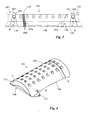
- the concrete element 101, 101', 101"; 201; 301 is intended for protecting one or several cables and/or pipelines in an underwater installation and comprises a bottom side 102; 302 providing a longitudinal cavity 103; 303 for receiving said one or several cables C and/or pipelines P when laying the concrete element.
- the concrete element 101 according to the invention is shaped as an elongated, curved shell segment having two gable ends 113, 114, a top side 115 between the gable ends, which is designed for low drag resistance against a trawl or other object dragged over it, after the laying operation, and at least two through-going apertures 116, 117 from the top side 115 to the cavity 103.
- the top side 115 decreases in height from the centre towards the sides 108, 109 and describes a smooth curve shape.
- a smooth curve shape of the top side also reduces the forces exerted by water movements on the concrete element after the laying operation, and thus also reduces the risk of the concrete element being displaced out of position.
- the concrete element 101 exhibits a pattern of through-going apertures 116, 117 across the major portion of its surface.
- the projection of the gable ends 113, 114 is inclined so that the top side 115 becomes longer than the bottom side 102, which creates openings for free through-flow of water between laid concrete elements and further reduces the forces exerted on the laid concrete elements by water movements. Furthermore, the openings between the concrete elements provide passages into the underlying cavity which are suitable for larger marine organisms, such as fish and lobsters.
- the concrete element 101; 301 according to the invention is advantageously provided with at least one connecting member 104, 105; 304, 305 for interconnection with a corresponding connecting member 105", 104' of another concrete element 101", 101' during the laying operation.
- the connecting members comprise lugs 104, 105 of corrosion resistant metal which can be interconnected by means of connecting elements, such as dowels, bolt-nut connections, pins, or other suitable elements.
- connecting elements such as dowels, bolt-nut connections, pins, or other suitable elements.
- Such a connecting system enables rapid interconnection of the concrete elements during the laying operation, so that they can be laid in shorter continuous groups, or in a long continuous row, in an efficient manner.
- the concrete elements lack connecting members and are laid one at a time on top of the installation which is to be protected.
- the connecting members 104, 105 of the concrete element 101, for interconnection with a corresponding connecting member of another concrete element have such a design that the space between the outer edges of the gable ends of two interconnected concrete elements becomes smaller than 30 cm, preferably smaller than 20 cm, after the laying operation.
- Such a small space between the gable ends reduces the risk of a trawl board, or other objects dragged over them, getting stuck between the concrete elements.
- the connecting members 104, 105 of the concrete element 101 are of a design which allows said one or several cables and/or pipelines P to be suspended therefrom and/or fixed thereto via one or several sling means 118, 118' when laying a plurality of concrete elements 101', 101, 101" in a row. It is also conceivable with an embodiment where the concrete element has been provided with other suitably positioned anchor points than the connecting members for such sling means, e.g. hooks or lugs on the bottom side of the concrete element.
- Such sling means 118, 118' is advantageous since it enables a portion of said one or several cables and/or pipelines P to be suspended from and/or fixed to the concrete elements in a simple, inexpensive and rapid manner when laying a plurality of concrete elements 101', 101, 101" in a row. It also enables said one or several cables and/or pipelines to be reliably fixed in position at regular intervals relative to the overlying protective structure of interconnected concrete elements in the completed underwater installation. Another advantage of such a flexible sling suspension is that the cables and/or pipelines can move sufficiently relative to the concrete elements during the laying operation to avoid that they are damaged by excessive tensile or bending forces, or jerks from the concrete elements.
- At least one resilient spacing means 106a, 106b; 206; 306a, 306b has been designed and applied in such a way on the concrete element 101; 201; 301, before the laying of the concrete element, that an abutment portion 107a, 107b; 307a, 307b of said resilient spacing means extends inside the longitudinal cavity 103; 303 at least a portion of the distance between a first 108; 208; 308 and a second 109; 209; 309 longitudinal side of the concrete element 101; 201; 301, wherein said resilient spacing means is/are intended to pass between said bottom side 102; 302 of the concrete element and said one or several cables C and/or pipelines P after the laying of the concrete element 101; 201; 301.
- the resiliency, degree of pretensioning, if any, and dimensioning of said resilient spacing means 106a, 106b; 206; 306a, 306b are chosen such that said resilient spacing means will exert a compressive force higher than 300 N/m, as measured on a cable or pipeline of 75 mm outer diameter, and expressed as force measured in N exerted on the cable or pipeline divided by the length in metres of the cable or pipeline on which said spacing means exerts the force with the concrete element resting on a flat support surface.
- the exerted compressive force is at least 300 N/m, it is ensured that the pipelines and/or cables will not move after the laying operation, so that the risk of interruptions in the fluid conveyance brought about by the pipelines is minimized, and so that, in particular, the risk of interruptions in power transmission and/or communication due to bending fatigue of the electrical or optical conductors of the cables is minimized.
- the resiliency, degree of pretensioning, if any, and dimensioning of said resilient spacing means 106a, 106b; 206; 306a, 306b are chosen such that said resilient spacing means will exert a compressive force below 5000 N/m, as measured on a cable or pipeline of 75 mm outer diameter, and expressed as force measured in N exerted on the cable or pipeline divided by the length in metres of the cable or pipeline on which said spacing means exerts the force with the concrete element resting on a flat support surface.
- the exerted compressive force can be measured before the laying operation by placing a piece of cable or pipe underneath a resilient spacing means of a concrete element according to the invention, which is then placed on a suitable flat support surface. Thereafter, the total force exerted on the piece of cable or pipe by the resilient spacing means is measured and divided by the width of the resilient spacing means in the longitudinal direction of the concrete element, i.e. the length of cable or pipe against which the resilient spacing means abuts.
- the determination of the exerted compressive force can advantageously be performed by placing the concrete element having a spacing means according to the invention on top of a piece of cable or pipe of 75 mm outer diameter, whereupon the force required for lifting the piece of cable or pipe from the support surface at the spacing means is measured. Thereafter, the measured force is divided by the measured width of the spacing means in contact with the piece of cable or pipe.
- a resilient spacing means 106a, 106b; 206; 306a, 306b according to the present invention is particularly advantageously dimensioned and adapted to at least substantially span the distance between the inwardly facing surfaces of the first 108; 208; 308 and second 109; 209; 309 longitudinal sides of the concrete element 101 on which the resilient spacing means is to be applied.
- Such a design minimizes the risk of cables and/or pipelines being damaged by wear or chafing against the inside of the concrete element during and/or after the laying operation.
- said resilient spacing means 106a, 106b comprises/comprise one or several elongated pieces of material in the form of a band, a belt, a strip, a fabric, a rope, a wire and/or a cord.
- a resilient spacing means 106a, 106b for application on a concrete element according to the first alternative embodiment can advantageously comprise a woven band of natural and/or synthetic material, and particularly advantageously a PVC coated woven fabric.
- the resilient spacing means 106a, 106b has an elongated shape and a length sufficient for application in the form of an endless, substantially transverse loop around the concrete element 101 and attachment of an attachment means 110 of said loop to at least one anchor point A on the concrete element.
- the resilient spacing means 206 has an elongated shape and exhibits a first end having a first attachment means 211 for attachment to a first anchor point B on the first longitudinal side 208 of the concrete element and second end having a second attachment means 212 for attachment to a second anchor point C on the second longitudinal side 209 of the concrete element.
- the attachment means of the spacing means used for attachment thereof to the anchor points of the concrete elements 101; 201 can advantageously comprise a loop of material wrapped around a rigid object, snap-in means 211, 212, lugs, straps, eyelets 110, apertures, slits, bundling straps and/or Velcro means, whereas the anchor points of the attachment means on or in the concrete elements 101; 201 advantageously can comprise dowels, hooks, lugs, eyelet holders (A), screws, bolts, nuts, washers, apertures, slits, borings, milled-out portions, recesses (B, C) and/or Velcro means.
- the periphery of the concrete element 201 is provided with at least one recess R for receiving, protecting and positionally fixing a portion of one of said resilient spacing means (not shown in the figure).
- a recess in the concrete element protects the resilient spacing means running in the recess from wear and chafing against objects in the surroundings and contributes to keeping the resilient spacing means in the intended position relative to the concrete element during and after the laying operation.
- said resilient spacing means 306a, 306b comprises/comprise one or several cut pieces of material of a sheet- or board-shaped resilient material, particularly advantageously one or several pieces of material 306a, 306b of a foamed or expanded material, which advantageously can be a polystyrene foam, and which alternatively can be a polyethylene, polypropylene or PVC foam. Combinations of several pieces of material of different materials may also be used as resilient spacing means.
- the concrete element 301 preferably exhibits at least one anchor point Da, Ea, Db, Eb for positionally fixing said resilient spacing means 306a, 306b, and particularly advantageously, the concrete element exhibits at least anchor point comprising at least one dowel, screw, nail, bolt, clip, slit, hook Da, Ea, Db, Eb (see Fig. 5 ), one or several protrusions and/or one or several means provided with spikes, barbs or nails for engagement with said resilient spacing means 306a, 306b.
- spacing means for example spacing means of different materials, of different shapes and dimensions, and with different attachment means for attachment to different types of anchor points of the concrete elements.
- the width of the spacing means can be selected for controlling the compressive force which will be exerted on the cables and/or pipelines which are to be protected by the concrete elements and pressed against a surface at the bottom via the spacing means. It has been found that a width of about 100 mm is suitable for most of the intended applications, but also other widths of the spacing means are conceivable, depending, among other things, on the type, material and number of spacing means, and on the type of pipes and/or cables which are to be protected by an interconnected row of laid concrete elements according to the invention in an underwater installation.
Landscapes
- Engineering & Computer Science (AREA)
- General Engineering & Computer Science (AREA)
- Mechanical Engineering (AREA)
- Laying Of Electric Cables Or Lines Outside (AREA)
Applications Claiming Priority (1)
| Application Number | Priority Date | Filing Date | Title |
|---|---|---|---|
| SE1300706A SE537639C2 (sv) | 2013-11-14 | 2013-11-14 | Betongelement för skydd av en eller flera kablar och/eller rörledningar i en undervattensinstallation |
Related Parent Applications (1)
| Application Number | Title | Priority Date | Filing Date |
|---|---|---|---|
| SE1300706 Previously-Filed-Application | 2013-11-14 |
Publications (3)
| Publication Number | Publication Date |
|---|---|
| EP2873897A2 true EP2873897A2 (fr) | 2015-05-20 |
| EP2873897A3 EP2873897A3 (fr) | 2015-05-27 |
| EP2873897B1 EP2873897B1 (fr) | 2017-06-14 |
Family
ID=52130183
Family Applications (1)
| Application Number | Title | Priority Date | Filing Date |
|---|---|---|---|
| EP14445005.3A Not-in-force EP2873897B1 (fr) | 2013-11-14 | 2014-11-11 | Élément de béton destiné à protéger une ou plusieurs câbles et/ou pipelines dans une installation sous-marine |
Country Status (2)
| Country | Link |
|---|---|
| EP (1) | EP2873897B1 (fr) |
| SE (1) | SE537639C2 (fr) |
Citations (4)
| Publication number | Priority date | Publication date | Assignee | Title |
|---|---|---|---|---|
| US4242010A (en) | 1977-08-19 | 1980-12-30 | Ingenior F. Selmer AS | Method and means for protecting a sea bottom surface and an installation on same |
| US6349808B1 (en) | 2000-03-24 | 2002-02-26 | Multicraft International | Cord rewinder device and horizontally-mounted electrical cord rewinder device for a vacuum cleaner |
| WO2005078325A1 (fr) | 2004-02-18 | 2005-08-25 | Sverre Meisingset | Dispositif de protection d'un element allonge sur un fond marin et procedes d'installation associes |
| WO2009136834A1 (fr) | 2008-05-06 | 2009-11-12 | Helgesson Bjoern | Élément de béton (1) destiné à protéger une installation sous-marine |
Family Cites Families (3)
| Publication number | Priority date | Publication date | Assignee | Title |
|---|---|---|---|---|
| US5052859A (en) * | 1988-08-12 | 1991-10-01 | Seamark Systems Limited | Seabed stabilization mattresses |
| GB8925502D0 (en) * | 1989-11-10 | 1989-12-28 | Seamark Systems | Seabed stabilisation mattresses |
| GB2242251B (en) * | 1990-02-23 | 1993-09-08 | Spuncon Pty Ltd | Stabilisation means |
-
2013
- 2013-11-14 SE SE1300706A patent/SE537639C2/sv not_active IP Right Cessation
-
2014
- 2014-11-11 EP EP14445005.3A patent/EP2873897B1/fr not_active Not-in-force
Patent Citations (4)
| Publication number | Priority date | Publication date | Assignee | Title |
|---|---|---|---|---|
| US4242010A (en) | 1977-08-19 | 1980-12-30 | Ingenior F. Selmer AS | Method and means for protecting a sea bottom surface and an installation on same |
| US6349808B1 (en) | 2000-03-24 | 2002-02-26 | Multicraft International | Cord rewinder device and horizontally-mounted electrical cord rewinder device for a vacuum cleaner |
| WO2005078325A1 (fr) | 2004-02-18 | 2005-08-25 | Sverre Meisingset | Dispositif de protection d'un element allonge sur un fond marin et procedes d'installation associes |
| WO2009136834A1 (fr) | 2008-05-06 | 2009-11-12 | Helgesson Bjoern | Élément de béton (1) destiné à protéger une installation sous-marine |
Also Published As
| Publication number | Publication date |
|---|---|
| EP2873897A3 (fr) | 2015-05-27 |
| SE1300706A1 (sv) | 2015-05-15 |
| EP2873897B1 (fr) | 2017-06-14 |
| SE537639C2 (sv) | 2015-09-01 |
Similar Documents
| Publication | Publication Date | Title |
|---|---|---|
| US7895716B2 (en) | Adjustable spiral sleeve for protecting lines | |
| US5944449A (en) | Non-Abrasive subsea mat | |
| SE416364B (sv) | Avspenningsdon | |
| US20030183291A1 (en) | Multi-compartment aerial duct | |
| JPS6075633A (ja) | 編成構造物 | |
| EP0152232A2 (fr) | Tapis de stabilisation | |
| EP2873897B1 (fr) | Élément de béton destiné à protéger une ou plusieurs câbles et/ou pipelines dans une installation sous-marine | |
| CN108883863B (zh) | 金属带 | |
| KR101499155B1 (ko) | 시공성 및 안정성이 향상된 해저케이블용 보호덮개 | |
| WO1981002054A1 (fr) | Appareil pour faire sauter un objet mobile d'un point a un autre et son procede d'utilisation | |
| WO2005078325A1 (fr) | Dispositif de protection d'un element allonge sur un fond marin et procedes d'installation associes | |
| JPS5843391Y2 (ja) | ケ−ブル架空支持装置 | |
| EP2053291A2 (fr) | Tapis non abrasif pour tapis de fond de mer articulé | |
| CN117530217B (zh) | 一种绳索网箱框架系统 | |
| JP6021996B1 (ja) | 汚濁防止膜 | |
| NO339200B1 (en) | Mooring system | |
| KR102857640B1 (ko) | 해저케이블 보호 어셈블리 | |
| CN215378405U (zh) | 一种水下管缆疲劳保护装置 | |
| JP3953081B2 (ja) | 係留用ロープの固定装置用保護カバー | |
| JP3039351U (ja) | 水中ケーブル | |
| JP4100109B2 (ja) | 砂面安定化構造体 | |
| PL134599B1 (en) | Hanger for mine cables and pipelines installed in dog headings | |
| AU2011100395A4 (en) | Mobile Flexible Element Support | |
| JPH0449304A (ja) | 水底被覆シート | |
| JP2014011836A (ja) | 架設ケーブル用カバーシートとこれを用いた架設ケーブル |
Legal Events
| Date | Code | Title | Description |
|---|---|---|---|
| PUAL | Search report despatched |
Free format text: ORIGINAL CODE: 0009013 |
|
| PUAI | Public reference made under article 153(3) epc to a published international application that has entered the european phase |
Free format text: ORIGINAL CODE: 0009012 |
|
| 17P | Request for examination filed |
Effective date: 20141202 |
|
| AK | Designated contracting states |
Kind code of ref document: A2 Designated state(s): AL AT BE BG CH CY CZ DE DK EE ES FI FR GB GR HR HU IE IS IT LI LT LU LV MC MK MT NL NO PL PT RO RS SE SI SK SM TR |
|
| AX | Request for extension of the european patent |
Extension state: BA ME |
|
| AK | Designated contracting states |
Kind code of ref document: A3 Designated state(s): AL AT BE BG CH CY CZ DE DK EE ES FI FR GB GR HR HU IE IS IT LI LT LU LV MC MK MT NL NO PL PT RO RS SE SI SK SM TR |
|
| AX | Request for extension of the european patent |
Extension state: BA ME |
|
| RIC1 | Information provided on ipc code assigned before grant |
Ipc: F16L 1/12 20060101AFI20150420BHEP |
|
| RIC1 | Information provided on ipc code assigned before grant |
Ipc: H02G 9/02 20060101ALI20161201BHEP Ipc: F16L 1/12 20060101AFI20161201BHEP |
|
| GRAP | Despatch of communication of intention to grant a patent |
Free format text: ORIGINAL CODE: EPIDOSNIGR1 |
|
| INTG | Intention to grant announced |
Effective date: 20170118 |
|
| GRAS | Grant fee paid |
Free format text: ORIGINAL CODE: EPIDOSNIGR3 |
|
| GRAA | (expected) grant |
Free format text: ORIGINAL CODE: 0009210 |
|
| AK | Designated contracting states |
Kind code of ref document: B1 Designated state(s): AL AT BE BG CH CY CZ DE DK EE ES FI FR GB GR HR HU IE IS IT LI LT LU LV MC MK MT NL NO PL PT RO RS SE SI SK SM TR |
|
| REG | Reference to a national code |
Ref country code: GB Ref legal event code: FG4D |
|
| REG | Reference to a national code |
Ref country code: CH Ref legal event code: EP Ref country code: AT Ref legal event code: REF Ref document number: 901314 Country of ref document: AT Kind code of ref document: T Effective date: 20170615 |
|
| REG | Reference to a national code |
Ref country code: IE Ref legal event code: FG4D |
|
| REG | Reference to a national code |
Ref country code: DE Ref legal event code: R096 Ref document number: 602014010734 Country of ref document: DE |
|
| REG | Reference to a national code |
Ref country code: NL Ref legal event code: MP Effective date: 20170614 |
|
| REG | Reference to a national code |
Ref country code: LT Ref legal event code: MG4D |
|
| PG25 | Lapsed in a contracting state [announced via postgrant information from national office to epo] |
Ref country code: FI Free format text: LAPSE BECAUSE OF FAILURE TO SUBMIT A TRANSLATION OF THE DESCRIPTION OR TO PAY THE FEE WITHIN THE PRESCRIBED TIME-LIMIT Effective date: 20170614 Ref country code: HR Free format text: LAPSE BECAUSE OF FAILURE TO SUBMIT A TRANSLATION OF THE DESCRIPTION OR TO PAY THE FEE WITHIN THE PRESCRIBED TIME-LIMIT Effective date: 20170614 Ref country code: LT Free format text: LAPSE BECAUSE OF FAILURE TO SUBMIT A TRANSLATION OF THE DESCRIPTION OR TO PAY THE FEE WITHIN THE PRESCRIBED TIME-LIMIT Effective date: 20170614 Ref country code: GR Free format text: LAPSE BECAUSE OF FAILURE TO SUBMIT A TRANSLATION OF THE DESCRIPTION OR TO PAY THE FEE WITHIN THE PRESCRIBED TIME-LIMIT Effective date: 20170915 Ref country code: NO Free format text: LAPSE BECAUSE OF FAILURE TO SUBMIT A TRANSLATION OF THE DESCRIPTION OR TO PAY THE FEE WITHIN THE PRESCRIBED TIME-LIMIT Effective date: 20170914 |
|
| REG | Reference to a national code |
Ref country code: AT Ref legal event code: MK05 Ref document number: 901314 Country of ref document: AT Kind code of ref document: T Effective date: 20170614 |
|
| PG25 | Lapsed in a contracting state [announced via postgrant information from national office to epo] |
Ref country code: NL Free format text: LAPSE BECAUSE OF FAILURE TO SUBMIT A TRANSLATION OF THE DESCRIPTION OR TO PAY THE FEE WITHIN THE PRESCRIBED TIME-LIMIT Effective date: 20170614 Ref country code: BG Free format text: LAPSE BECAUSE OF FAILURE TO SUBMIT A TRANSLATION OF THE DESCRIPTION OR TO PAY THE FEE WITHIN THE PRESCRIBED TIME-LIMIT Effective date: 20170914 Ref country code: SE Free format text: LAPSE BECAUSE OF FAILURE TO SUBMIT A TRANSLATION OF THE DESCRIPTION OR TO PAY THE FEE WITHIN THE PRESCRIBED TIME-LIMIT Effective date: 20170614 Ref country code: RS Free format text: LAPSE BECAUSE OF FAILURE TO SUBMIT A TRANSLATION OF THE DESCRIPTION OR TO PAY THE FEE WITHIN THE PRESCRIBED TIME-LIMIT Effective date: 20170614 Ref country code: LV Free format text: LAPSE BECAUSE OF FAILURE TO SUBMIT A TRANSLATION OF THE DESCRIPTION OR TO PAY THE FEE WITHIN THE PRESCRIBED TIME-LIMIT Effective date: 20170614 |
|
| PG25 | Lapsed in a contracting state [announced via postgrant information from national office to epo] |
Ref country code: CZ Free format text: LAPSE BECAUSE OF FAILURE TO SUBMIT A TRANSLATION OF THE DESCRIPTION OR TO PAY THE FEE WITHIN THE PRESCRIBED TIME-LIMIT Effective date: 20170614 Ref country code: RO Free format text: LAPSE BECAUSE OF FAILURE TO SUBMIT A TRANSLATION OF THE DESCRIPTION OR TO PAY THE FEE WITHIN THE PRESCRIBED TIME-LIMIT Effective date: 20170614 Ref country code: AT Free format text: LAPSE BECAUSE OF FAILURE TO SUBMIT A TRANSLATION OF THE DESCRIPTION OR TO PAY THE FEE WITHIN THE PRESCRIBED TIME-LIMIT Effective date: 20170614 Ref country code: SK Free format text: LAPSE BECAUSE OF FAILURE TO SUBMIT A TRANSLATION OF THE DESCRIPTION OR TO PAY THE FEE WITHIN THE PRESCRIBED TIME-LIMIT Effective date: 20170614 Ref country code: EE Free format text: LAPSE BECAUSE OF FAILURE TO SUBMIT A TRANSLATION OF THE DESCRIPTION OR TO PAY THE FEE WITHIN THE PRESCRIBED TIME-LIMIT Effective date: 20170614 |
|
| PG25 | Lapsed in a contracting state [announced via postgrant information from national office to epo] |
Ref country code: IT Free format text: LAPSE BECAUSE OF FAILURE TO SUBMIT A TRANSLATION OF THE DESCRIPTION OR TO PAY THE FEE WITHIN THE PRESCRIBED TIME-LIMIT Effective date: 20170614 Ref country code: PL Free format text: LAPSE BECAUSE OF FAILURE TO SUBMIT A TRANSLATION OF THE DESCRIPTION OR TO PAY THE FEE WITHIN THE PRESCRIBED TIME-LIMIT Effective date: 20170614 Ref country code: SM Free format text: LAPSE BECAUSE OF FAILURE TO SUBMIT A TRANSLATION OF THE DESCRIPTION OR TO PAY THE FEE WITHIN THE PRESCRIBED TIME-LIMIT Effective date: 20170614 Ref country code: ES Free format text: LAPSE BECAUSE OF FAILURE TO SUBMIT A TRANSLATION OF THE DESCRIPTION OR TO PAY THE FEE WITHIN THE PRESCRIBED TIME-LIMIT Effective date: 20170614 Ref country code: IS Free format text: LAPSE BECAUSE OF FAILURE TO SUBMIT A TRANSLATION OF THE DESCRIPTION OR TO PAY THE FEE WITHIN THE PRESCRIBED TIME-LIMIT Effective date: 20171014 |
|
| REG | Reference to a national code |
Ref country code: DE Ref legal event code: R097 Ref document number: 602014010734 Country of ref document: DE |
|
| PLBE | No opposition filed within time limit |
Free format text: ORIGINAL CODE: 0009261 |
|
| STAA | Information on the status of an ep patent application or granted ep patent |
Free format text: STATUS: NO OPPOSITION FILED WITHIN TIME LIMIT |
|
| PG25 | Lapsed in a contracting state [announced via postgrant information from national office to epo] |
Ref country code: DK Free format text: LAPSE BECAUSE OF FAILURE TO SUBMIT A TRANSLATION OF THE DESCRIPTION OR TO PAY THE FEE WITHIN THE PRESCRIBED TIME-LIMIT Effective date: 20170614 |
|
| 26N | No opposition filed |
Effective date: 20180315 |
|
| PG25 | Lapsed in a contracting state [announced via postgrant information from national office to epo] |
Ref country code: MC Free format text: LAPSE BECAUSE OF FAILURE TO SUBMIT A TRANSLATION OF THE DESCRIPTION OR TO PAY THE FEE WITHIN THE PRESCRIBED TIME-LIMIT Effective date: 20170614 |
|
| PG25 | Lapsed in a contracting state [announced via postgrant information from national office to epo] |
Ref country code: LI Free format text: LAPSE BECAUSE OF NON-PAYMENT OF DUE FEES Effective date: 20171130 Ref country code: CH Free format text: LAPSE BECAUSE OF NON-PAYMENT OF DUE FEES Effective date: 20171130 |
|
| PG25 | Lapsed in a contracting state [announced via postgrant information from national office to epo] |
Ref country code: SI Free format text: LAPSE BECAUSE OF FAILURE TO SUBMIT A TRANSLATION OF THE DESCRIPTION OR TO PAY THE FEE WITHIN THE PRESCRIBED TIME-LIMIT Effective date: 20170614 Ref country code: LU Free format text: LAPSE BECAUSE OF NON-PAYMENT OF DUE FEES Effective date: 20171111 |
|
| REG | Reference to a national code |
Ref country code: FR Ref legal event code: ST Effective date: 20180731 Ref country code: BE Ref legal event code: MM Effective date: 20171130 |
|
| REG | Reference to a national code |
Ref country code: IE Ref legal event code: MM4A |
|
| PG25 | Lapsed in a contracting state [announced via postgrant information from national office to epo] |
Ref country code: MT Free format text: LAPSE BECAUSE OF NON-PAYMENT OF DUE FEES Effective date: 20171111 |
|
| PG25 | Lapsed in a contracting state [announced via postgrant information from national office to epo] |
Ref country code: IE Free format text: LAPSE BECAUSE OF NON-PAYMENT OF DUE FEES Effective date: 20171111 Ref country code: FR Free format text: LAPSE BECAUSE OF NON-PAYMENT OF DUE FEES Effective date: 20171130 |
|
| PG25 | Lapsed in a contracting state [announced via postgrant information from national office to epo] |
Ref country code: BE Free format text: LAPSE BECAUSE OF NON-PAYMENT OF DUE FEES Effective date: 20171130 |
|
| PG25 | Lapsed in a contracting state [announced via postgrant information from national office to epo] |
Ref country code: HU Free format text: LAPSE BECAUSE OF FAILURE TO SUBMIT A TRANSLATION OF THE DESCRIPTION OR TO PAY THE FEE WITHIN THE PRESCRIBED TIME-LIMIT; INVALID AB INITIO Effective date: 20141111 |
|
| PG25 | Lapsed in a contracting state [announced via postgrant information from national office to epo] |
Ref country code: CY Free format text: LAPSE BECAUSE OF FAILURE TO SUBMIT A TRANSLATION OF THE DESCRIPTION OR TO PAY THE FEE WITHIN THE PRESCRIBED TIME-LIMIT Effective date: 20170614 |
|
| PG25 | Lapsed in a contracting state [announced via postgrant information from national office to epo] |
Ref country code: MK Free format text: LAPSE BECAUSE OF FAILURE TO SUBMIT A TRANSLATION OF THE DESCRIPTION OR TO PAY THE FEE WITHIN THE PRESCRIBED TIME-LIMIT Effective date: 20170614 |
|
| PGFP | Annual fee paid to national office [announced via postgrant information from national office to epo] |
Ref country code: DE Payment date: 20191120 Year of fee payment: 6 |
|
| PG25 | Lapsed in a contracting state [announced via postgrant information from national office to epo] |
Ref country code: TR Free format text: LAPSE BECAUSE OF FAILURE TO SUBMIT A TRANSLATION OF THE DESCRIPTION OR TO PAY THE FEE WITHIN THE PRESCRIBED TIME-LIMIT Effective date: 20170614 |
|
| PGFP | Annual fee paid to national office [announced via postgrant information from national office to epo] |
Ref country code: GB Payment date: 20191118 Year of fee payment: 6 |
|
| PG25 | Lapsed in a contracting state [announced via postgrant information from national office to epo] |
Ref country code: PT Free format text: LAPSE BECAUSE OF FAILURE TO SUBMIT A TRANSLATION OF THE DESCRIPTION OR TO PAY THE FEE WITHIN THE PRESCRIBED TIME-LIMIT Effective date: 20170614 |
|
| PG25 | Lapsed in a contracting state [announced via postgrant information from national office to epo] |
Ref country code: AL Free format text: LAPSE BECAUSE OF FAILURE TO SUBMIT A TRANSLATION OF THE DESCRIPTION OR TO PAY THE FEE WITHIN THE PRESCRIBED TIME-LIMIT Effective date: 20170614 |
|
| REG | Reference to a national code |
Ref country code: DE Ref legal event code: R119 Ref document number: 602014010734 Country of ref document: DE |
|
| GBPC | Gb: european patent ceased through non-payment of renewal fee |
Effective date: 20201111 |
|
| PG25 | Lapsed in a contracting state [announced via postgrant information from national office to epo] |
Ref country code: DE Free format text: LAPSE BECAUSE OF NON-PAYMENT OF DUE FEES Effective date: 20210601 Ref country code: GB Free format text: LAPSE BECAUSE OF NON-PAYMENT OF DUE FEES Effective date: 20201111 |