EP2874005A2 - Method for entering an image and related medium - Google Patents
Method for entering an image and related medium Download PDFInfo
- Publication number
- EP2874005A2 EP2874005A2 EP20140186497 EP14186497A EP2874005A2 EP 2874005 A2 EP2874005 A2 EP 2874005A2 EP 20140186497 EP20140186497 EP 20140186497 EP 14186497 A EP14186497 A EP 14186497A EP 2874005 A2 EP2874005 A2 EP 2874005A2
- Authority
- EP
- European Patent Office
- Prior art keywords
- opaque
- image
- opaque layer
- cell
- etched
- Prior art date
- Legal status (The legal status is an assumption and is not a legal conclusion. Google has not performed a legal analysis and makes no representation as to the accuracy of the status listed.)
- Withdrawn
Links
- 238000000034 method Methods 0.000 title claims abstract description 87
- 239000000758 substrate Substances 0.000 claims abstract description 73
- 238000005530 etching Methods 0.000 claims abstract description 49
- 239000011159 matrix material Substances 0.000 claims abstract description 28
- 238000000151 deposition Methods 0.000 claims abstract description 23
- 238000000206 photolithography Methods 0.000 claims description 52
- 238000012216 screening Methods 0.000 claims description 20
- 239000000463 material Substances 0.000 claims description 15
- 238000009432 framing Methods 0.000 claims description 13
- 238000000354 decomposition reaction Methods 0.000 claims description 11
- 230000008021 deposition Effects 0.000 claims description 8
- 238000005286 illumination Methods 0.000 claims 1
- 239000010410 layer Substances 0.000 description 224
- 230000033458 reproduction Effects 0.000 description 32
- 230000005540 biological transmission Effects 0.000 description 31
- MUMZUERVLWJKNR-UHFFFAOYSA-N oxoplatinum Chemical compound [Pt]=O MUMZUERVLWJKNR-UHFFFAOYSA-N 0.000 description 12
- 229910003446 platinum oxide Inorganic materials 0.000 description 12
- 239000012780 transparent material Substances 0.000 description 12
- 230000003287 optical effect Effects 0.000 description 9
- 238000003860 storage Methods 0.000 description 7
- 238000001514 detection method Methods 0.000 description 6
- VYPSYNLAJGMNEJ-UHFFFAOYSA-N silicon dioxide Inorganic materials O=[Si]=O VYPSYNLAJGMNEJ-UHFFFAOYSA-N 0.000 description 6
- 230000000694 effects Effects 0.000 description 5
- 238000006073 displacement reaction Methods 0.000 description 4
- 230000010070 molecular adhesion Effects 0.000 description 4
- 238000004026 adhesive bonding Methods 0.000 description 3
- 239000003086 colorant Substances 0.000 description 3
- 150000001875 compounds Chemical class 0.000 description 3
- 239000011347 resin Substances 0.000 description 3
- 229920005989 resin Polymers 0.000 description 3
- 229910004298 SiO 2 Inorganic materials 0.000 description 2
- 238000009792 diffusion process Methods 0.000 description 2
- 239000011521 glass Substances 0.000 description 2
- 238000009434 installation Methods 0.000 description 2
- JEIPFZHSYJVQDO-UHFFFAOYSA-N iron(III) oxide Inorganic materials O=[Fe]O[Fe]=O JEIPFZHSYJVQDO-UHFFFAOYSA-N 0.000 description 2
- BASFCYQUMIYNBI-UHFFFAOYSA-N platinum Chemical compound [Pt] BASFCYQUMIYNBI-UHFFFAOYSA-N 0.000 description 2
- 239000010453 quartz Substances 0.000 description 2
- 229910052594 sapphire Inorganic materials 0.000 description 2
- 239000010980 sapphire Substances 0.000 description 2
- 239000000377 silicon dioxide Substances 0.000 description 2
- 239000002356 single layer Substances 0.000 description 2
- 229910018072 Al 2 O 3 Inorganic materials 0.000 description 1
- VYZAMTAEIAYCRO-UHFFFAOYSA-N Chromium Chemical compound [Cr] VYZAMTAEIAYCRO-UHFFFAOYSA-N 0.000 description 1
- 241001080024 Telles Species 0.000 description 1
- NRTOMJZYCJJWKI-UHFFFAOYSA-N Titanium nitride Chemical compound [Ti]#N NRTOMJZYCJJWKI-UHFFFAOYSA-N 0.000 description 1
- 240000008042 Zea mays Species 0.000 description 1
- 230000001174 ascending effect Effects 0.000 description 1
- 230000008033 biological extinction Effects 0.000 description 1
- 230000015572 biosynthetic process Effects 0.000 description 1
- 239000000969 carrier Substances 0.000 description 1
- 229910052804 chromium Inorganic materials 0.000 description 1
- 239000011651 chromium Substances 0.000 description 1
- 230000007547 defect Effects 0.000 description 1
- 238000010586 diagram Methods 0.000 description 1
- 229920002457 flexible plastic Polymers 0.000 description 1
- 238000001459 lithography Methods 0.000 description 1
- 230000007774 longterm Effects 0.000 description 1
- 238000004519 manufacturing process Methods 0.000 description 1
- 230000000873 masking effect Effects 0.000 description 1
- 229910052751 metal Inorganic materials 0.000 description 1
- 239000002184 metal Substances 0.000 description 1
- TWNQGVIAIRXVLR-UHFFFAOYSA-N oxo(oxoalumanyloxy)alumane Chemical compound O=[Al]O[Al]=O TWNQGVIAIRXVLR-UHFFFAOYSA-N 0.000 description 1
- 229920002120 photoresistant polymer Polymers 0.000 description 1
- 229920003023 plastic Polymers 0.000 description 1
- 230000010287 polarization Effects 0.000 description 1
- 238000011084 recovery Methods 0.000 description 1
Images


Classifications
-
- G—PHYSICS
- G03—PHOTOGRAPHY; CINEMATOGRAPHY; ANALOGOUS TECHNIQUES USING WAVES OTHER THAN OPTICAL WAVES; ELECTROGRAPHY; HOLOGRAPHY
- G03F—PHOTOMECHANICAL PRODUCTION OF TEXTURED OR PATTERNED SURFACES, e.g. FOR PRINTING, FOR PROCESSING OF SEMICONDUCTOR DEVICES; MATERIALS THEREFOR; ORIGINALS THEREFOR; APPARATUS SPECIALLY ADAPTED THEREFOR
- G03F7/00—Photomechanical, e.g. photolithographic, production of textured or patterned surfaces, e.g. printing surfaces; Materials therefor, e.g. comprising photoresists; Apparatus specially adapted therefor
- G03F7/20—Exposure; Apparatus therefor
- G03F7/2022—Multi-step exposure, e.g. hybrid; backside exposure; blanket exposure, e.g. for image reversal; edge exposure, e.g. for edge bead removal; corrective exposure
-
- G—PHYSICS
- G03—PHOTOGRAPHY; CINEMATOGRAPHY; ANALOGOUS TECHNIQUES USING WAVES OTHER THAN OPTICAL WAVES; ELECTROGRAPHY; HOLOGRAPHY
- G03F—PHOTOMECHANICAL PRODUCTION OF TEXTURED OR PATTERNED SURFACES, e.g. FOR PRINTING, FOR PROCESSING OF SEMICONDUCTOR DEVICES; MATERIALS THEREFOR; ORIGINALS THEREFOR; APPARATUS SPECIALLY ADAPTED THEREFOR
- G03F7/00—Photomechanical, e.g. photolithographic, production of textured or patterned surfaces, e.g. printing surfaces; Materials therefor, e.g. comprising photoresists; Apparatus specially adapted therefor
- G03F7/12—Production of screen printing forms or similar printing forms, e.g. stencils
-
- G—PHYSICS
- G03—PHOTOGRAPHY; CINEMATOGRAPHY; ANALOGOUS TECHNIQUES USING WAVES OTHER THAN OPTICAL WAVES; ELECTROGRAPHY; HOLOGRAPHY
- G03F—PHOTOMECHANICAL PRODUCTION OF TEXTURED OR PATTERNED SURFACES, e.g. FOR PRINTING, FOR PROCESSING OF SEMICONDUCTOR DEVICES; MATERIALS THEREFOR; ORIGINALS THEREFOR; APPARATUS SPECIALLY ADAPTED THEREFOR
- G03F7/00—Photomechanical, e.g. photolithographic, production of textured or patterned surfaces, e.g. printing surfaces; Materials therefor, e.g. comprising photoresists; Apparatus specially adapted therefor
- G03F7/20—Exposure; Apparatus therefor
- G03F7/2051—Exposure without an original mask, e.g. using a programmed deflection of a point source, by scanning, by drawing with a light beam, using an addressed light or corpuscular source
-
- G—PHYSICS
- G11—INFORMATION STORAGE
- G11B—INFORMATION STORAGE BASED ON RELATIVE MOVEMENT BETWEEN RECORD CARRIER AND TRANSDUCER
- G11B7/00—Recording or reproducing by optical means, e.g. recording using a thermal beam of optical radiation by modifying optical properties or the physical structure, reproducing using an optical beam at lower power by sensing optical properties; Record carriers therefor
- G11B7/24—Record carriers characterised by shape, structure or physical properties, or by the selection of the material
- G11B7/26—Apparatus or processes specially adapted for the manufacture of record carriers
- G11B7/261—Preparing a master, e.g. exposing photoresist, electroforming
Definitions
- the present invention relates to the field of photolithographic inscription of an image on a support, and more particularly the field of image archiving methods.
- the archiving of an image here designates the storage of a reproduction of this image for later reading "by transparency”. It is usually a reproduction in reduced dimensions of this image, often in a single copy.
- image designates any graphic representation such as a photograph, a text, a table, a drawing, etc.
- the invention also relates to the field of image carriers made using such methods.
- the dithering step consists of converting a grayscale image into a black and white image, made of a matrix of cells of the same size, called “screening cells".
- the term "gray level" may also designate gradations of intensity of a color.
- frequency modulation screening is known in which each cell is homogeneous: entirely black or entirely white.
- Amplitude modulation dithering is also known in which each cell contains a shape of variable size written in white on black or in black on white.
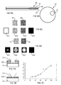
- Figure 1A an image to archive.
- the Figure 1B represents this image after amplitude modulation dithering.
- the figure 1C represents this image after a framing by frequency modulation.
- the reading of the archiving medium is ensured by a low-pass filter which eliminates the fine variations of the screening structure below the cell scale, keeping only the evolutions averaged over a few cells.
- the archiving medium can for example be read by simple optical magnification means.
- the archiving medium 31 is illuminated by a light source 32.
- An optic 33 images the archiving medium 31 on a detector 34 such as a matrix detector.
- the optic 33 has an optical transfer function which introduces an optical blur comparable to a Gaussian spot width (we speak of "waist") equal to a few pixels, typically two or three.
- the magnification of the optics 33 is adapted to match the size of a screening cell with the pixel size of the matrix detector 34.
- the dark shades coded in the storage medium 31 are relative to the opaque layer and the hues clear to the etched openings in the opaque layer and releasing the surface of the transparent substrate.
- the image 35 is obtained on the matrix detector 34.
- a high-definition image is 8-bit encoded: each pixel in the image can take a gray level from 256 ( 28 ) available gray levels.
- the known solution is that one pixel of the image corresponds to a large number of screening cells.
- a disadvantage of such a solution is that the area of the archiving medium corresponding to this high definition image is increased.
- An object of the present invention is to provide a method of writing a source image, which does not present at least one of the disadvantages of the prior art.
- an object of the present invention is to provide a method of registering a source image by photolithography, which allows a compact writing of source images.
- an objective of the present invention is to propose a method of registering a source image by photolithography, which allows a compact writing of source images in high definition, typically a definition of at least 8 bits, for example 16 bits.
- Another object of the present invention is to provide an image support obtained using such a method.
- a layer of an opaque material, or opaque layer means a layer whose transmission coefficient is lower than that of the first substrate. This transmission coefficient can be zero, as long as it allows the formation of the elementary pattern obtained by the superimposed layers.
- the transmission coefficient is defined for the wavelengths of the visible, preferably between 400 nm and 800 nm.
- the first and second opaque layers preferably have respective degrees of opacity different from each other.
- the degree of opacity designates the rate or extinction coefficient, that is to say the inverse of the rate or transmission coefficient.
- the degree of opacity is preferably defined for the wavelengths of the visible, preferably between 400 nm and 800 nm.
- the first and second opaque layers preferably have different thicknesses and are formed by the same material. Opaque and first and second opaque layers are thus produced with respective degrees of opacity different from each other.
- first and second opaque layers may each consist of a different material. These materials advantageously have different properties of light transmission. It is thus possible to produce first and second opaque layers having the same thickness, and with respective degrees of opacity different from each other.
- the deposition of the second opaque layer is performed after the etching of the first opaque layer.
- the etching of the second opaque layer may be performed before or after deposition of the second opaque layer on the first etched opaque layer.
- an image to be decomposed is decomposed according to an HSV decomposition to obtain a "hue” component, a “saturation” component, and a “light intensity” component, the "hue” and “saturation” components are entered in the high definition archive area, and the "light intensity” component is entered in the low definition archive area.
- the first opaque layer and the second opaque layer may have different thicknesses, each thickness being between 10 nm and 200 nm.
- Each first cell and second cell may be either fully etched or ungraved.
- each first cell and second cell may be integrally etched, or non-etched, or etched to form a transparent closed surface in an opaque-edge cell or a closed opaque surface in a transparent-border cell, with closed surfaces formed. in different first cells having different dimensions, closed surfaces formed in different second cells having different dimensions.
- the invention also relates to a system comprising an image carrier according to the invention and means for reading in transparency (or in other words transmission reading) of the reproduction of a source image situated in this image carrier.
- the transparency reading means comprise a light source located on one side of said image carrier, and a detector located on the side of the image carrier opposite to the light source.
- FIGS. 1A, 1B, 1C, 2A, 2B, and 3 have already been described in the introduction.
- the recording method according to the invention comprises a first step 401 of depositing, on a first transparent substrate 41, a first opaque layer 42. At this stage, the first opaque layer 42 forms a matrix 43 of first cells 430 all identical and opaque.
- the first opaque layer 42 is etched by photolithography.
- the photolithography etching may be a maskless etching, particularly in the context of the archiving of a single copy of a source image.
- the photolithography etching may be a mask etching.
- a mask etching implements an etching of a set of patterns in a source mask.
- the set of patterns is reproduced on substrates, in as many copies as desired, by projections through this mask.
- This variant is advantageous for a reproduction of an image in several copies. This will be the case, for example, for product marking applications in order to identify with certainty the manufacturer of this product.
- a matrix 44 of first cells 440 is thus formed, each having one of several predetermined patterns.
- the first opaque layer is engraved throughout its thickness.
- a second opaque layer 45 is deposited, so that this second opaque layer 45 is between the first opaque layer 42 and a second transparent substrate 46, and this second opaque layer is etched.
- the second transparent substrate 46 serves as a layer protection for opaque opaque layers.
- the method according to the invention is not limited to an order between the steps of deposition of the second opaque layer 45 and etching thereof, as shown in the examples which follow.
- the second opaque layer 45 is also etched by photolithography (with or without a mask). The second opaque layer is engraved throughout its thickness.
- This etching forms a matrix 47 of second cells 470 each having one of several predetermined patterns.
- the superposition of the matrix 44 of the first cells on the matrix 47 of second cells forms a matrix 48 of cells 480 each having an elementary pattern formed by the superposition of a second pattern on a first pattern. At least one elementary pattern is formed by superimposing a second pattern on a first pattern, said second pattern being different from the first pattern.
- the matrix 48 is a matrix of elementary patterns and corresponds to a reproduction in reduced dimensions of a source image, this source image having been rasterized.
- the invention makes it possible to obtain, for a given cell size, a larger number of elementary patterns available for constructing a reproduction in reduced dimensions of a source image. It will be possible to encode all the gray levels of a high definition image using a small number of cells. A compact archiving of a source image in high definition is thus performed, typically a definition of at least 8 bits.
- the etchings use photolithography methods, offering etching resolutions in an opaque layer of the order of 1 ⁇ m.
- the first substrate is not necessarily transparent, and the second opaque layer 46 is not covered with a second transparent substrate.
- This variant corresponds to a simple inscription, by photolithography, of an image on a support.
- the method according to the invention offers there again excellent image definition for a reduced registration area.
- This variant is advantageously combined with the implementation of etchings by photolithography with a mask.
- the Figure 5A illustrates a side view of an image carrier 50 shown schematically and obtained using a registration method according to the invention. It is more particularly a storage medium 50, obtained by means of an archiving method as described with reference to the figure 4 .
- the matrix of elementary patterns defined above is formed in a high definition archival area 51, between the first transparent substrate 41 and the second transparent substrate 46.
- Figure 5B illustrates a front view of the archive medium 50 shown schematically.
- the first transparent substrate and the second transparent substrate each consist for example of a quartz or sapphire layer.
- the first transparent substrate and the second transparent substrate may also be formed of a flexible plastic material or a rigid plastic material such as those used to make the optical disks.
- the thickness of the first and second transparent substrates is of the order of mm, for example less than 1 mm, in particular equal to 0.7 mm.
- Each opaque layer consists for example of a metal layer such as a chromium layer, a titanium nitride layer layer, or a platinum oxide layer PtO x .
- the thickness of an opaque layer is generally less than 200 nm, or even less than 100 nm, for example equal to 60 nm, 40 nm or 30 nm.
- the Figure 6A illustrates a first example of combinations of first and second cells, forming the elementary patterns according to the invention.
- the first non-etched cell 61 has a transmission coefficient greater than that of the second non-etched cell 62.
- the transmission coefficient depends on the thickness of the corresponding opaque layer. For example, a layer 40 nm thick platinum oxide has a transmission coefficient close to 5%, while a layer 30 nm thick platinum oxide has a transmission coefficient close to 10 %.
- These four elementary patterns 631, 632, 633, 634 define four coding patterns available in the context of a frequency modulation framing.
- the gray level of such a coding pattern corresponds to the transmission coefficient of the associated elementary pattern.
- one pixel of the source image can be subdivided into several zones to be associated with an encoding pattern.
- Each opaque layer is etched to achieve a predetermined checkerboard.
- the Figure 6B illustrates a second example of combinations of first and second cells, forming the elementary patterns according to the invention.
- the Figure 6B corresponds to the case of an amplitude modulated screening.
- Each first cell 61 is either fully etched, not etched, or etched to draw a transparent closed surface in an opaque edge cell or an opaque closed surface in a transparent edge cell.
- non-circular openings for example oval.
- An opening is considered to have a circular or oval shape, without taking into account the edge defects related to photolithography etching.
- opaque forms on a transparent background Each cell may also be etched according to openings of different dimensions, for example discs of different diameters.
- the solutions can be varied from one opaque layer to another.
- laser impacts can be achieved by displacing the laser beam from the center of the cell.
- laser impacts can be achieved by displacing the laser beam on the edges of the cell.
- the four basic patterns 641, 642, 643, 644 define four coding patterns available in the context of an amplitude modulated framing.
- the gray level of such a coding pattern corresponds to the average transmission coefficient of the associated elementary pattern.
- each pixel is coded using the coding pattern whose gray level is closest to the gray level of said pixel.
- one pixel of the source image can be subdivided into several zones to be associated with an encoding pattern.
- amplitude modulation framing over frequency modulation framing is that there is a direct link between a pixel in the source image and the associated elementary pattern.
- the Figure 7A illustrates a maskless photolithography step of a thick opaque layer 421.
- the thickness of the opaque layer associated with the conical shape of the focused laser beam 21, implies a minimum opening size that can be etched in the layer
- the minimum aperture is a disk of 4 ⁇ m in diameter.
- photolithography without an indirect mask or photolithography with a mask the same phenomenon is observed: if the chemical compound reaches the opaque layer at depth, it also spreads laterally.
- the Figure 7B illustrates a maskless photolithography step of a thin opaque layer 422.
- the thickness of the opaque layer implies a minimum aperture size that can be etched in the thin opaque layer 422. This minimum size is all the more reduced that the layer is thin. For example, for a thickness of 25 nm opaque layer of platinum oxide, the minimum aperture is a disc 0.6 ⁇ m in diameter.
- the Figure 7C illustrates a graph showing the minimum diameter of a disk that can be etched in an opaque layer of platinum oxide by maskless photolithography, depending on the thickness of the opaque layer.
- the x-axis is graduated in nm.
- the y-axis is graduated in ⁇ m. This figure illustrates the fact that the minimum size of an opening that can be etched in the opaque layer is even smaller than the layer is thin. It should be noted that this minimum opening size also depends on the diffraction limit of the engraving tool.
- the predetermined openings are the openings that can be etched in successive steps of enlargement of the opening, starting from the minimum opening size.
- the successive steps correspond, for example, to displacements of the laser beam on the cell, or to increases in the intensity of the fixed laser beam.
- the dark shades coded in the archiving medium are relative to the opaque layer and the light colors are relative to the etched openings in the opaque layer.
- dark hue and light hue must be the most extreme possible.
- the light source will be powered to generate a signal as close as possible to the high linear detection limit of the matrix detector.
- the only adjustment variable relates to the transmission coefficient of the opaque layer.
- the invention in that it proposes the superposition of at least two opaque layers, offers a clever way of reconciling these two criteria. With the aid of a thin opaque first layer, it is possible to engrave small openings. Thanks to the superposition of at least two opaque layers, it is possible to achieve very low transmission coefficients corresponding to the stack of layers, for example less than 5%. Preferably, different thicknesses will be chosen for each of the opaque layers according to the invention.
- each opaque layer is then engraved in the form of a checkerboard, where each square of the checkerboard is either entirely engraved or ungraved.
- a small thickness of the opaque layer makes it possible to make checkerboard boxes of small dimensions. Overlaying opaque layers, however, avoids the loss of reading dynamics.
- the first opaque layer has a transmission T a .
- the second opaque layer has a transmission T b .
- T a transmission
- T b transmission
- each cell of the first opaque layer is etched a disc of radius r a , centered on the cell.
- r b disc of radius r b , centered on the cell.
- Each cell is a side square ⁇ .
- ⁇ ab T at . T b x ⁇ 2 + T at . 1 - T b x ⁇ . r b 2 + 1 - T at x ⁇ . r at 2 ⁇ 1 ⁇ 2
- the gray level corresponds to surfaces of a cell weighted by corresponding transmission coefficients, the whole related to the total surface of the cell.
- each pixel may have one of 256 different gray levels, the gray levels being regularly spaced from white to black, it is desired to have at its disposal a library of 256 elementary patterns, such as we find at best this regular spacing gray levels corresponding, ranging from white to black.
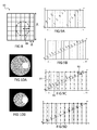
- the figure 8 illustrates a cell 80 of the first opaque layer according to the invention.
- the cell is a square of side ⁇ .
- an addressing grid corresponding to a matrix of squares with a side ⁇ is defined. This grid corresponds to the elementary displacements of a laser beam used for etching, relative to the cell 80.
- this cell is etched a disk of minimum radius ⁇ .
- Enlarged apertures can be etched with one or more elementary displacement (s) of the laser beam relative to the cell 80.
- NMSK ⁇ 2 - ⁇ . ⁇ 2 ⁇ 2
- NMSK ab NMSK at ⁇ NMSK b
- Nmsk a 349, for the dimensions ⁇ , ⁇ and ⁇ previously mentioned.
- Nmsk b 371, for the same dimensions ⁇ and ⁇ , and for a value of ⁇ slightly lower (thickness of the opaque layer b lower than that of the opaque layer a ).
- Nmsk ab 129 4793.
- the Figure 9A illustrates a diagram in which 16 available elementary patterns A to P are represented, regularly spaced along an abscissa axis.
- the ordinate axis corresponds to the calculated or measured average transmission coefficient corresponding to each elementary pattern.
- each first available pattern is combined successively with all second available patterns.
- the elementary patterns are arranged in ascending order of average transmission coefficient.
- the vertical bars 91 in dotted lines each represent one of the X desired coding patterns.
- the dotted line 92 connects the two desired ends for coding. These ends respectively correspond to a completely transparent elementary pattern and a completely opaque elementary pattern.
- the points A to P are translated horizontally, so as to place them as close as possible to the points of intersection between the straight line 92 and each of the vertical bars 91. It can be seen, for example, that the point N, translated horizontally along the arrow 93, is placed exactly on one of these points of intersection.
- the horizontal axis corresponds to the abscissa axis of the orthogonal reference marks of the Figures 9A to 9D .
- this elementary pattern is removed from the elementary pattern library shown in FIG. Figure 9D . It is replaced by another basic pattern, chosen by example in elementary patterns removed during the passage of the Figure 9C to the Figure 9D .
- the first transparent substrate 41 is covered with the first opaque layer 42.
- the first opaque layer 42 is etched by photolithography (step 115).
- the second transparent substrate 46 is covered with the second opaque layer 45.
- the second opaque layer 45 is etched by photolithography (step 116).
- the assembly formed of the second transparent substrate 46 and the second opaque layer 45 is deposited and adhered to the first opaque layer 42, so that the second opaque layer 45 is between the first opaque layer 42 and the second opaque layer 42. transparent substrate 46.
- bonding is achieved by a resin layer 110 deposited on the first or second opaque layer (step 117).
- the bonding is carried out by molecular adhesion.
- a layer of transparent material 111, 112 is deposited on each of the first and second opaque layers 42, 45. Then, these layers of transparent material 111, 112 are polished.
- transparent is for example Al 2 O 3 aluminum oxide or SiO 2 silica. The layers of transparent material are finally deposited one on the other, and remain connected to each other by molecular adhesion (step 118).
- the second opaque layer 45 is returned to paste it on the first opaque layer. It is therefore necessary to provide the etching of the second opaque layer 45 accordingly.
- the currently available gluing devices offer an alignment accuracy for this last gluing step of the order of ⁇ 1 ⁇ m, which makes it possible to use a side square cell ⁇ equal to at least 2 ⁇ m (cf. figure 8 ).
- the figure 12 illustrates a second embodiment of the registration method according to the invention.
- the first transparent substrate 41 is covered with the first opaque layer 42.
- the first opaque layer 42 is etched by photolithography (step 120).
- a layer of transparent material 121 is deposited on the opaque layer previously etched (step 122).
- This transparent material is for example silica SiO 2 .
- a flat surface is thus obtained on the side of the transparent material opposite the first layer of opaque material 42.
- a new opaque layer 45 is deposited on the transparent material 121.
- the new opaque layer 45 is etched by photolithography (step 123).
- the method then comprises a final step 124 for bonding the second transparent substrate 46 to the opaque layer 125 previously etched.
- this last bonding step may be carried out using a resin or by molecular adhesion.
- This embodiment has the advantage of allowing to superpose more than two opaque layers.
- the alignment of the opaque layers relative to each other is facilitated by the fact that the etching of an opaque layer is done after its deposition on the lower opaque layer (s). Indeed, the alignment accuracy of the engraving is better than that of the collage. 200 nm accuracies are commonly achieved using commercial laser writing equipment.
- the expansion of the substrates remains less than 1 ⁇ m, provided that the temperature is stabilized at 0.7 ° C for sapphire, to within 0.5 ° C for glass, at 10 ° C for quartz. Clean rooms using lithography and gluing equipment are stabilized and controlled in temperature. Substrate support plates guarantee thermal uniformity at +/- 0.5 ° C. It can thus be seen that these authorized temperature variations are in agreement with what is technically feasible.
- the figure 13 illustrates a third embodiment of an inscription method according to the invention, which is a variant of the method illustrated in FIG. figure 12 .
- the process illustrated in figure 13 differs from the illustrated process in figure 12 in that the steps of depositing a transparent material and depositing a new opaque layer are replaced by a step of bonding to the previously etched opaque layer of an intermediate transparent substrate 131 (step 132).
- a new opaque layer 45 may have been deposited on the intermediate transparent substrate 131 before bonding 132.
- a new opaque layer 45 is deposited on the intermediate transparent substrate 131 after bonding 132.
- the bonding is for example carried out using a resin 133. In a variant, it is produced by molecular adhesion.
- the intermediate transparent substrate 131 is for example a glass sheet with a thickness of 30 ⁇ m to 100 ⁇ m.
- the figure 14 illustrates a fourth embodiment of the registration method according to the invention.
- the first transparent substrate 41 is covered with the first opaque layer 42.
- the first opaque layer 42 is etched by photolithography (step 140).
- the method then comprises a step 142 of depositing, directly on the opaque layer previously etched, a new opaque layer 45.
- the new opaque layer 45 is then etched by photolithography (step 143).
- the method then comprises a final step 144 for bonding the second transparent substrate 46 to the previously etched opaque layer.
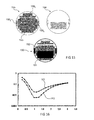
- the figure 15 illustrates an archiving medium 150 according to the invention, comprising a high definition archiving area 151 (in black) and a low archiving area definition 152 (in gray).
- the high definition archive area does not correspond to the total extent of the data archived in the archive medium 150.
- a source image corresponds to a low archiving zone or high definition and the same medium receives several reproductions of source images.
- Part 155 represents the main part of the media, with the thickest opaque layer. It contains a document storage area 155 1 , a reference area 155 2 (media title, table of contents, ...) and calibration areas and alignment patterns 155 3 .
- the reference zone 155 2 does not present high definition information, it does not therefore require the implementation of the method according to the invention.
- the document storage area 155 1 may also include low definition data that can be processed by a single opaque layer method according to the prior art. These areas, which do not have high definition information, are therefore not found in the second part 156 of the archive medium. The processing of the second part 156 of the archive medium can thus be accelerated.
- a color image In the case where a color image must be archived, it is decomposed into three components, each component being archived independently. It is expected that some components are archived using a single opaque layer, as in the prior art, and that other components are archived using at least two opaque layers superimposed, by a method archiving according to the invention.
- an image is decomposed on HSV or LAB.
- the color component (s) determines the color dynamics of the image.
- it will be chosen to archive the chromatic component (s) by a method according to the invention, in the high-definition archival area 151 of the archive medium.
- the other components are archived in the low-definition archive area 152 of the archive medium.
- an image to be decomposed according to a LAB decomposition is decomposed to obtain a luminous intensity component, a first chromatic component, and a second chromatic component.
- the first and second color components are stored in the high definition archiving area 151, and the light intensity component is stored in the low definition archive area 152.
- An image to be archived can also be decomposed according to an HSV decomposition to obtain a "hue” component, a “saturation” component, and a “light intensity” component.
- the "hue” and “saturation” components are stored in the high-definition archiving area 151, and the "light intensity” component is stored in the low-definition archiving area 152.
- a component can also be favored by providing a reduced reproduction of this component of the image, according to a lower reduction factor.
- the figure 16 illustrates a comparison of the mean squared error between a source image and its representation in the form of elementary patterns, in the case of archiving according to the prior art and in the case of archiving according to the invention.
- a source image is compared with the image obtained after optical detection of its representation in the form of elementary patterns.
- the optical detection is that described with reference to the figure 3 , using an optics that introduces an optical blur comparable to a Gaussian spot of width wg. It is an optical detection by Gaussian convolution.
- the abscissa axis corresponds to the width wg of the Gaussian relative to the size of the cell.
- the y-axis corresponds to the mean squared error relative to the source image.
- the source image is a pattern of gray scale tones made up of 20x20 different gray tones randomly distributed spatially and dynamically from 0 to 255.
- the zones have an extension of 3x3 pixels, ie an image to code of 60x60 pixels.
- Curve 161 corresponds to an archiving method according to the prior art using a single layer of platinum oxide 45 nm thick and an amplitude modulation screening using circular openings in opaque cells.
- the pitch of the addressing grid is 0.02 ⁇ m.
- a square cell with side ⁇ equal to 2 ⁇ m is used (see figure 8 ).
- the minimum error is about 2%.
- Curve 162 corresponds to an archiving method according to the invention using two layers of platinum oxide with thicknesses of 45 nm and 30 nm, and amplitude modulation screening using circular openings in cells. opaque.
- the pitch of the addressing grid is 0.02 ⁇ m and a square cell with a side ⁇ equal to 2 ⁇ m is used.
- the minimum error is about 0.6%, about 3 times less than the error obtained with the method according to the prior art and under similar conditions.
- the invention is not limited to the described embodiments.
Landscapes
- Physics & Mathematics (AREA)
- General Physics & Mathematics (AREA)
- Engineering & Computer Science (AREA)
- Manufacturing & Machinery (AREA)
- Exposure And Positioning Against Photoresist Photosensitive Materials (AREA)
Abstract
L'invention concerne un procédé d'inscription d'une image source, dans lequel on réalise sous la forme d'une matrice de motifs élémentaires, une reproduction de l'image source. Le procédé comprend les étapes suivantes : - dépôt (401) sur un premier substrat (41) d'une première couche opaque (42) ; - gravure (402) de la première couche opaque (42), de façon à former une matrice de premières cellules (440) présentant chacune un parmi plusieurs premiers motifs prédéterminés ; - dépôt d'au moins une deuxième couche opaque (45) ; et - gravure de la deuxième couche opaque (45), de façon à former une matrice de deuxièmes cellules (470) présentant chacune un parmi plusieurs deuxièmes motifs prédéterminés, les motifs élémentaires étant définis par la superposition d'un deuxième motif et d'un premier motif. L'invention concerne également un support d'image obtenu à l'aide d'un tel procédé.The invention relates to a method for registering a source image, in which a reproduction of the source image is produced in the form of a matrix of elementary patterns. The method comprises the following steps: depositing (401) on a first substrate (41) a first opaque layer (42); etching (402) the opaque first layer (42) to form a matrix of first cells (440) each having one of a plurality of predetermined first patterns; depositing at least one opaque second layer (45); and etching the second opaque layer (45), so as to form a matrix of second cells (470) each having one of several second predetermined patterns, the elementary patterns being defined by the superimposition of a second pattern and a first pattern. The invention also relates to an image carrier obtained by using such a method.
Description
La présente invention concerne le domaine de l'inscription par photolithographie d'une image sur un support, et plus particulièrement le domaine des procédés d'archivage d'une image.The present invention relates to the field of photolithographic inscription of an image on a support, and more particularly the field of image archiving methods.
L'archivage d'une image désignera ici le stockage d'une reproduction de cette image en vue d'une lecture ultérieure « par transparence ». Il s'agit généralement d'une reproduction en dimensions réduites de cette image, souvent en un seul exemplaire.The archiving of an image here designates the storage of a reproduction of this image for later reading "by transparency". It is usually a reproduction in reduced dimensions of this image, often in a single copy.
Dans tout le texte, le terme « image » désigne toute représentation graphique telle qu'une photographie, un texte, un tableau, un dessin, etc.Throughout the text, the term "image" designates any graphic representation such as a photograph, a text, a table, a drawing, etc.
L'invention concerne également le domaine des supports d'image réalisés à l'aide de tels procédés.The invention also relates to the field of image carriers made using such methods.
On connaît dans l'art antérieur de nombreux procédés d'inscription par photolithographie d'une image sur un support. On présentera ici plus particulièrement le domaine de l'archivage d'une image, bien que l'invention présentée par la suite puisse être étendue au domaine plus large de l'inscription d'une image par photolithographie.Numerous methods for the photolithographic inscription of an image on a support are known in the prior art. The field of archiving an image will be presented here more particularly, although the invention presented hereinafter may be extended to the wider field of photolithography of an image.
On a l'habitude de stocker les images sous forme numérique, sur des supports de stockage tels que des disques durs d'ordinateur, et des disques optiques numériques enregistrables (CD ROM, DVD, etc.). De tels supports présentent cependant une durée de vie limitée, typiquement de l'ordre d'une dizaine d'années. En outre, les formats de codage peuvent devenir obsolètes et empêcher la récupération de l'image à partir des données numériques stockées.It is customary to store images in digital form, on storage media such as computer hard drives, and recordable digital optical discs (CD ROMs, DVDs, etc.). Such supports, however, have a limited life, typically of the order of ten years. In addition, the encoding formats may become obsolete and prevent the recovery of the image from the stored digital data.
On connaît dans l'art antérieur différents procédés offrant des solutions d'archivage à long terme pour un encombrement réduit. Ces procédés consistent à réaliser un tramage de l'image, puis à graver par photolithographie sans masque une couche d'un matériau opaque déposé sur un substrat transparent, pour reproduire en dimensions réduites l'image tramée. On obtient ainsi un support d'archivage, dans lequel une image est archivée en format analogique. On trouvera dans le document
L'étape de tramage consiste à convertir une image en niveaux de gris, en une image en noir et blanc, faite d'une matrice de cellules de mêmes dimensions, dénommées « cellules de tramage ». Le terme « niveau de gris » pourra également désigner des dégradés d'intensité d'une couleur. On connaît par exemple le tramage par modulation de fréquence, dans lequel chaque cellule est homogène : entièrement noire ou entièrement blanche. On connaît également le tramage par modulation d'amplitude dans lequel chaque cellule contient une forme de taille variable inscrite en blanc sur noir ou en noir sur blanc. On a représenté à la
La gravure par photolithographie sans masque se fait par écriture directe au laser, sans étape de masquage de zones prédéfinies. La gravure par photolithographie sans masque peut être une gravure directe : le matériau opaque est photosensible et le faisceau laser est appliqué directement sur la couche de matériau opaque. La
- on recouvre la couche opaque 25 d'une couche sacrificielle photosensible 26 telle qu'une résine photosensible ;
- on applique le faisceau laser sur la couche sacrificielle photosensible 26 de façon à transformer le matériau dans les zones insolées ;
- on grave les zones transformées de la
couche 26 de manière à rendre accessible lacouche 25 au regard deszones 27 découvertes ; - on grave le matériau opaque 25 en appliquant un composé chimique auquel la couche sacrificielle photosensible 26 restante est insensible et la couche opaque 25 est sensible : de cette façon le composé chimique grave la couche opaque 25 à travers l'ouverture 27 ;
- on élimine la couche sacrificielle photosensible 26.
- the
opaque layer 25 is covered with a photosensitivesacrificial layer 26 such as a photoresist; - the laser beam is applied to the photosensitive
sacrificial layer 26 so as to transform the material into the exposed areas; - the transformed zones of the
layer 26 are etched so as to make thelayer 25 accessible to thezones 27 discovered; - the
opaque material 25 is etched by applying a chemical compound to which the remaining photosensitivesacrificial layer 26 is insensitive and theopaque layer 25 is sensitive: in this way the chemical compound etches theopaque layer 25 through theaperture 27; - the photosensitive
sacrificial layer 26 is eliminated.
La lecture du support d'archivage est assurée par un filtre passe bas qui supprime les variations fines de la structure du tramage en dessous de l'échelle de la cellule pour ne garder que les évolutions moyennées à l'échelle de quelques cellules. Le support d'archivage peut par exemple être lu par de simples moyens d'agrandissement optiques. Le support d'archivage 31 est éclairé par une source lumineuse 32. Une optique 33 image le support d'archivage 31 sur un détecteur 34 tel qu'un détecteur matriciel. L'optique 33 présente une fonction de transfert optique qui introduit un flou optique assimilable à une tache gaussienne de largeur (on parle de « waist ») égale à quelques pixels, typiquement deux ou trois. Le grossissement de l'optique 33 est adapté pour faire correspondre la taille d'une cellule de tramage avec la taille du pixel du détecteur matriciel 34. Les teintes sombres codées dans le support d'archivage 31 sont relatives à la couche opaque et les teintes claires aux ouvertures gravées dans la couche opaque et libérant la surface du substrat transparent. On obtient l'image 35 sur le détecteur matriciel 34.The reading of the archiving medium is ensured by a low-pass filter which eliminates the fine variations of the screening structure below the cell scale, keeping only the evolutions averaged over a few cells. The archiving medium can for example be read by simple optical magnification means. The archiving
Si l'image est en couleurs, plusieurs reproductions sont archivées, correspondant à la décomposition de l'image en trois composantes par exemple :
- rouge, vert, bleu (décomposition RVB) ; ou
- teinte, saturation, intensité lumineuse (décomposition HSV) ; ou
- intensité lumineuse, première composante chromatique pour les couleurs entre le vert et le rouge, deuxième composante chromatique pour les couleurs entre le bleu et le jaune (décomposition LAB).
- red, green, blue (RGB decomposition); or
- hue, saturation, light intensity (HSV decomposition); or
- luminous intensity, first color component for colors between green and red, second color component for colors between blue and yellow (LAB decomposition).
Les procédés existants utilisent typiquement en tant que couche opaque une couche d'oxyde de platine PtOx de 60 nm environ d'épaisseur, où x est notamment un réel compris entre 1 et 2. Une telle couche d'oxyde de platine présente une transmission inférieure à 5%, pour une taille minimum d'ouverture correspondant à un disque de 1,5 µm de diamètre.Existing methods typically use as opaque layer a layer of platinum oxide PtO x about 60 nm thick, where x is in particular a real between 1 and 2. Such a layer of platinum oxide has a transmission less than 5%, for a minimum opening size corresponding to a disc of 1.5 microns in diameter.
Ces procédés présentent des limitations, dans le cas où l'on souhaite archiver des images en haute définition. Ces images en haute définition sont réalisées par exemple à l'aide des nouvelles générations d'appareil photo numérique.These methods have limitations, in the case where it is desired to archive images in high definition. These high definition images are made for example using the new generations of digital camera.
Par exemple, une image en haute définition est codée sur 8 bits : chaque pixel de l'image peut prendre un niveau de gris parmi 256 (28) niveaux de gris disponibles. Pour coder autant de niveaux de gris dans le support d'archivage, la solution connue est qu'un pixel de l'image corresponde à un grand nombre de cellules de tramage. Un inconvénient d'une telle solution est alors que l'on augmente la surface de la zone du support d'archivage correspondant à cette image en haute définition.For example, a high-definition image is 8-bit encoded: each pixel in the image can take a gray level from 256 ( 28 ) available gray levels. To code as many gray levels in the archive medium, the known solution is that one pixel of the image corresponds to a large number of screening cells. A disadvantage of such a solution is that the area of the archiving medium corresponding to this high definition image is increased.
Un objectif de la présente invention est de proposer un procédé d'inscription d'une image source, qui ne présente pas au moins l'un des inconvénients de l'art antérieur.An object of the present invention is to provide a method of writing a source image, which does not present at least one of the disadvantages of the prior art.
En particulier, un objectif de la présente invention est de proposer un procédé d'inscription d'une image source par photolithographie, qui permette une écriture compacte d'images sources.In particular, an object of the present invention is to provide a method of registering a source image by photolithography, which allows a compact writing of source images.
En particulier, un objectif de la présente invention est de proposer un procédé d'inscription d'une image source par photolithographie, qui permette une écriture compacte d'images sources en haute définition, typiquement une définition d'au moins 8 bits, par exemple 16 bits.In particular, an objective of the present invention is to propose a method of registering a source image by photolithography, which allows a compact writing of source images in high definition, typically a definition of at least 8 bits, for example 16 bits.
Un autre objectif de la présente invention est de proposer un support d'image obtenu à l'aide d'un tel procédé.Another object of the present invention is to provide an image support obtained using such a method.
La présente invention est définie par un procédé d'inscription d'une image source, dans lequel on réalise sous la forme d'une matrice de motifs élémentaires, une reproduction de l'image source, le procédé comprenant les étapes suivantes :
- dépôt sur un premier substrat d'une première couche opaque ;
- gravure de la première couche opaque sur toute son épaisseur, par photolithographie, de façon à former une matrice de premières cellules présentant chacune un parmi plusieurs premiers motifs prédéterminés.
- depositing on a first substrate a first opaque layer;
- etching of the first opaque layer over its entire thickness, by photolithography, so as to form a matrix of first cells each having one of several first predetermined patterns.
Le procédé selon l'invention comprend en outre les étapes suivantes :
- un dépôt d'au moins une deuxième couche opaque, de façon à ce que la deuxième couche opaque se superpose à la première couche opaque ; et
- une gravure de ladite deuxième couche opaque sur toute son épaisseur, par photolithographie, de façon à former sur la deuxième couche opaque une matrice de deuxièmes cellules présentant chacune un parmi plusieurs deuxièmes motifs prédéterminés, lesdits motifs élémentaires étant chacun définis par la superposition d'un premier motif parmi lesdits premiers motifs prédéterminés et d'un second motif parmi lesdits deuxièmes motifs prédéterminés, et au moins un motif élémentaire étant défini par la superposition d'un premier motif sur un second motif de forme différente.
- a deposit of at least a second opaque layer, so that the second opaque layer is superimposed on the first opaque layer; and
- an etching of said second opaque layer over its entire thickness, by photolithography, so as to form on the second opaque layer a matrix of second cells each having one of several second predetermined patterns, said elementary patterns being each defined by the superposition of a first pattern among said first predetermined patterns and a second pattern of said second predetermined patterns, and at least one elemental pattern being defined by superimposing a first pattern on a second pattern of different shape.
Dans tout le texte, une couche d'un matériau opaque, ou couche opaque, désigne une couche dont le coefficient de transmission est inférieur à celui du premier substrat. Ce coefficient de transmission peut être nul, du moment qu'il permet la formation du motif élémentaire obtenu par les couches superposées. Le coefficient de transmission est défini pour les longueurs d'onde du visible, de préférence entre 400 nm et 800 nm.Throughout the text, a layer of an opaque material, or opaque layer, means a layer whose transmission coefficient is lower than that of the first substrate. This transmission coefficient can be zero, as long as it allows the formation of the elementary pattern obtained by the superimposed layers. The transmission coefficient is defined for the wavelengths of the visible, preferably between 400 nm and 800 nm.
De préférence, le procédé d'inscription selon l'invention réalise un archivage d'une image source dans un support d'archivage comprenant un premier substrat transparent et un second substrat transparent. Selon un tel procédé :
- le dépôt de la première couche opaque est réalisé sur le premier substrat transparent ;
- les étapes de gravure sont réalisées par photolithographie sans masque ; et
- le dépôt d'une deuxième couche opaque est réalisé de façon à ce que la deuxième couche opaque se trouve entre la première couche opaque et le deuxième substrat transparent.
- depositing the first opaque layer is performed on the first transparent substrate;
- the etching steps are performed by photolithography without a mask; and
- depositing a second opaque layer is made so that the second opaque layer is between the first opaque layer and the second transparent substrate.
Les première et seconde couches opaques présentent de préférence des degrés d'opacité respectifs différents l'un de l'autre. Le degré d'opacité désigne le taux ou coefficient d'extinction, c'est-à-dire l'inverse du taux ou coefficient de transmission. Le degré d'opacité est défini de préférence pour les longueurs d'onde du visible, de préférence entre 400 nm et 800 nm.The first and second opaque layers preferably have respective degrees of opacity different from each other. The degree of opacity designates the rate or extinction coefficient, that is to say the inverse of the rate or transmission coefficient. The degree of opacity is preferably defined for the wavelengths of the visible, preferably between 400 nm and 800 nm.
Les première et seconde couches opaques présentent de préférence des épaisseurs différentes et sont formées par un même matériau. On réalise ainsi des première et seconde couches opaques présentant des degrés d'opacité respectifs différents l'un de l'autre.The first and second opaque layers preferably have different thicknesses and are formed by the same material. Opaque and first and second opaque layers are thus produced with respective degrees of opacity different from each other.
En variante, les première et seconde couches opaques peuvent consister chacune en un matériau différent. Ces matériaux présentent avantageusement des propriétés différentes de transmission de la lumière. On peut ainsi réaliser des première et seconde couches opaques présentant une même épaisseur, et avec des degrés d'opacité respectifs différents l'un de l'autre.Alternatively, the first and second opaque layers may each consist of a different material. These materials advantageously have different properties of light transmission. It is thus possible to produce first and second opaque layers having the same thickness, and with respective degrees of opacity different from each other.
Le procédé selon l'invention peut comprendre une étape initiale de codage de l'image source, selon un tramage à modulation de fréquence ou un tramage à modulation d'amplitude, le tramage mettant en oeuvre des motifs élémentaires selon l'invention. Selon un mode de réalisation avantageux :
- chaque première cellule et deuxième cellule est soit intégralement gravée, soit non gravée, définissant ainsi par superposition une première série de motifs élémentaires disponibles pour réaliser la reproduction de l'image source ; et
- on réalise un tramage à modulation de fréquence de l'image source, à l'aide de motifs de codage choisis parmi ladite première série de motifs élémentaires.
- each first cell and second cell is either fully etched or non-etched, thereby defining by superposition a first series of elementary patterns available to perform the reproduction of the source image; and
- frequency-modulated framing of the source image is performed using encoding patterns selected from said first series of elementary patterns.
Selon une variante de ce mode de réalisation :
- chaque première cellule et deuxième cellule est gravée, ou non gravée, ou gravée de façon à former une surface fermée transparente dans une cellule à bords opaques ou une surface fermée opaque dans une cellule à bords transparents, définissant ainsi par superposition une seconde série de motifs élémentaires disponibles pour réaliser la reproduction de l'image source ; et
- on réalise un tramage à modulation d'amplitude de l'image source, à l'aide de motifs de codage choisis parmi ladite seconde série de motifs élémentaires.
- each first cell and second cell is etched, or not etched, or etched to form a transparent closed surface in an opaque-edge cell or an opaque closed surface in a transparent-border cell, thereby superimposing a second set of patterns elementary available to perform the reproduction of the source image; and
- an amplitude modulated screening of the source image is performed using coding patterns selected from said second series of elementary patterns.
Le procédé selon l'invention, lorsqu'il réalise un archivage tel que décrit ci-dessus, peut comprendre les étapes suivantes :
- dépôt de la deuxième couche opaque sur le deuxième substrat transparent ;
- gravure, par photolithographie, de la deuxième couche opaque ;
- collage, sur la première couche opaque, de la deuxième couche opaque déposée sur le deuxième substrat transparent.
- depositing the opaque second layer on the second transparent substrate;
- etching, by photolithography, of the second opaque layer;
- bonding, on the first opaque layer, the second opaque layer deposited on the second transparent substrate.
En variante, le procédé selon l'invention, lorsqu'il réalise un archivage tel que décrit ci-dessus, peut comprendre les étapes suivantes :
- au moins un cycle comprenant les étapes suivantes :
- dépôt d'un matériau transparent sur la première couche opaque précédemment gravée ;
- dépôt de la seconde couche opaque sur le matériau transparent ;
- gravure, par photolithographie, de la nouvelle couche opaque ;
- collage du deuxième substrat transparent sur la seconde couche opaque précédemment gravée.
- at least one cycle comprising the following steps:
- depositing a transparent material on the previously opaque first opaque layer;
- depositing the opaque second layer on the transparent material;
- etching, by photolithography, of the new opaque layer;
- bonding the second transparent substrate to the second opaque layer previously etched.
En variante, le procédé selon l'invention, lorsqu'il réalise un archivage tel que décrit ci-dessus, peut comprendre les étapes suivantes :
- au moins un cycle comprenant les étapes suivantes :
- collage, sur la première couche opaque précédemment gravée, d'un substrat transparent intermédiaire ;
- gravure, par photolithographie, de la seconde couche opaque déposée sur le substrat transparent intermédiaire ;
- collage du deuxième substrat sur la seconde couche opaque précédemment gravée.
- at least one cycle comprising the following steps:
- bonding, on the first opaque layer previously etched, an intermediate transparent substrate;
- etching, by photolithography, of the second opaque layer deposited on the intermediate transparent substrate;
- bonding the second substrate to the previously opaque second opaque layer.
En variante, le procédé selon l'invention, lorsqu'il réalise un archivage tel que décrit ci-dessus, peut comprendre les étapes suivantes :
- au moins un cycle comprenant des étapes suivantes :
- dépôt, sur la première couche opaque précédemment gravée, de la seconde couche opaque ;
- gravure, par photolithographie, de la seconde couche opaque ;
- collage du deuxième substrat transparent sur la seconde couche opaque précédemment gravée.
- at least one cycle comprising the following steps:
- depositing, on the first opaque layer previously etched, the second opaque layer;
- etching, by photolithography, of the second opaque layer;
- bonding the second transparent substrate to the second opaque layer previously etched.
Ainsi, dans chacune de ces variantes, le dépôt de la deuxième couche opaque est réalisé après la gravure de la première couche opaque.Thus, in each of these variants, the deposition of the second opaque layer is performed after the etching of the first opaque layer.
La gravure de la deuxième couche opaque peut être réalisée avant ou après dépôt de la deuxième couche opaque sur la première couche opaque gravée.The etching of the second opaque layer may be performed before or after deposition of the second opaque layer on the first etched opaque layer.
Le procédé selon l'invention, lorsqu'il réalise un archivage tel que décrit ci-dessus, peut comprendre les étapes suivantes :
- décomposition selon trois composantes d'une image à archiver;
- inscription desdites trois composantes, chacune dans une zone d'archivage du support d'archivage et entre le premier substrat transparent et le deuxième substrat transparent, au moins une desdites composantes étant inscrite dans une zone d'archivage, dite zone d'archivage haute définition à l'aide d'un procédé réalisant un archivage tel que décrit ci-dessus, et au moins une desdites composantes étant inscrite dans une zone d'archivage, dite zone d'archivage basse définition, et en gravant, par photolithographie une unique couche opaque.
- decomposition according to three components of an image to be archived;
- registration of said three components, each in an archive area of the archive medium and between the first transparent substrate and the second transparent substrate, at least one of said components being inscribed in an archiving area, called high definition archive area using a method performing an archiving as described above, and at least one of said components being inscribed in an archive area, said low-resolution archive area, and by photolithographically etching a single layer opaque.
De préférence, on décompose une image à archiver selon une décomposition HSV pour obtenir une composante « teinte », une composante « saturation », et une composante « intensité lumineuse », on inscrit les composantes « teinte » et « saturation » dans la zone d'archivage haute définition, et on inscrit la composante « intensité lumineuse » dans la zone d'archivage basse définition.Preferably, an image to be decomposed is decomposed according to an HSV decomposition to obtain a "hue" component, a "saturation" component, and a "light intensity" component, the "hue" and "saturation" components are entered in the high definition archive area, and the "light intensity" component is entered in the low definition archive area.
Le procédé selon l'invention comprend avantageusement une étape de lecture en transparence (ou autrement dit lecture en transmission) de la reproduction d'une image source, comprenant les étapes suivantes :
- éclairage de ladite reproduction à l'aide d'une source lumineuse située d'un côté de ladite reproduction ;
- détection d'une image de ladite reproduction, à l'aide d'un détecteur situé du côté de ladite reproduction opposé à la source lumineuse.
- illuminating said reproduction with a light source on one side of said reproduction;
- detecting an image of said reproduction, using a detector located on the side of said reproduction opposite to the light source.
L'invention concerne également un support d'image dans lequel est stockée, sous la forme d'une juxtaposition de motifs élémentaires, une reproduction d'une image source, ledit support d'image comprenant, sur un premier substrat, une première couche opaque gravée sur toute son épaisseur par photolithographie et formant une matrice de premières cellules présentant chacune un parmi plusieurs premiers motifs prédéterminés. Le support selon l'invention présente les caractéristiques suivantes :
- le support d'image comprend au moins une deuxième couche opaque gravée sur toute son épaisseur par photolithographie, formant une matrice de deuxièmes cellules, chaque deuxième cellule présentant un parmi plusieurs deuxièmes motifs prédéterminés ; et
- la deuxième couche opaque est située sur la première couche opaque de façon à définir lesdits motifs élémentaires, formés par la superposition d'un premier motif et un deuxième motif, et au moins un motif élémentaire étant défini par la superposition d'un premier motif sur un second motif de forme différente.
- the image carrier comprises at least one opaque second layer etched throughout its thickness by photolithography, forming a matrix of second cells, each second cell having one of a plurality of second predetermined patterns; and
- the second opaque layer is located on the first opaque layer so as to define said elementary patterns, formed by the superposition of a first pattern and a second pattern, and at least one elemental pattern being defined by the superposition of a first pattern on a second pattern of different shape.
Le support d'image selon l'invention peut former un support d'archivage de l'image source et :
- comprendre au moins une zone d'archivage dite haute définition dans laquelle est stockée la reproduction de l'image source ;
- comprendre un premier substrat transparent et un second substrat transparent, la première couche opaque étant située sur le premier substrat transparent et la deuxième couche opaque étant située entre la première couche opaque et le deuxième substrat transparent.
- include at least one so-called high definition archive area in which the reproduction of the source image is stored;
- comprising a first transparent substrate and a second transparent substrate, the first opaque layer being located on the first transparent substrate and the second opaque layer being located between the first opaque layer and the second transparent substrate.
La première couche opaque et la deuxième couche opaque peuvent présenter des épaisseurs différentes, chaque épaisseur étant comprise entre 10 nm et 200 nm.The first opaque layer and the second opaque layer may have different thicknesses, each thickness being between 10 nm and 200 nm.
Chaque première cellule et deuxième cellule peut être soit intégralement gravée, soit non gravée.Each first cell and second cell may be either fully etched or ungraved.
En variante, chaque première cellule et deuxième cellule peut être intégralement gravée, ou non gravée, ou gravée de façon à former une surface fermée transparente dans une cellule à bords opaques ou une surface fermée opaque dans une cellule à bords transparents, des surfaces fermées formées dans différentes premières cellules présentant des dimensions différentes, des surfaces fermées formées dans différentes deuxièmes cellules présentant des dimensions différentes.Alternatively, each first cell and second cell may be integrally etched, or non-etched, or etched to form a transparent closed surface in an opaque-edge cell or a closed opaque surface in a transparent-border cell, with closed surfaces formed. in different first cells having different dimensions, closed surfaces formed in different second cells having different dimensions.
Dans un mode de réalisation préféré, le support d'image est un support d'archivage et il comprend :
- une première zone d'archivage haute définition, dans laquelle est stockée une reproduction d'une première image source correspondant à une première parmi trois composantes d'une image à archiver;
- une première zone d'archivage basse définition, dans laquelle est stockée une reproduction d'une deuxième image source correspondant à la deuxième composante de l'image à archiver, la zone d'archivage basse définition comprenant, entre le premier substrat transparent et le second substrat transparent, une unique couche opaque gravée par photolithographie ; et
- une deuxième zone d'archivage haute définition ou une deuxième zone d'archivage basse définition, dans laquelle est stockée une reproduction d'une troisième image source correspondant à la troisième composante de l'image à archiver.
- a first high definition archive area, in which is stored a reproduction of a first source image corresponding to a first of three components of an image to be archived;
- a first low-definition archive area, in which is stored a reproduction of a second source image corresponding to the second component of the image to be archived, the low-definition storage area comprising, between the first transparent substrate and the second transparent substrate, a single opaque layer etched by photolithography; and
- a second high definition archive area or a second low definition archive area, in which is stored a reproduction of a third source image corresponding to the third component of the image to be archived.
L'invention concerne également un système comprenant un support d'image selon l'invention et des moyens de lecture en transparence (ou autrement dit lecture en transmission) de la reproduction d'une image source située dans ce support d'image.The invention also relates to a system comprising an image carrier according to the invention and means for reading in transparency (or in other words transmission reading) of the reproduction of a source image situated in this image carrier.
Les moyens de lecture en transparence comprennent une source lumineuse située d'un côté dudit support d'image, et un détecteur situé du côté du support d'image opposé à la source lumineuse.The transparency reading means comprise a light source located on one side of said image carrier, and a detector located on the side of the image carrier opposite to the light source.
La présente invention sera mieux comprise à la lecture de la description d'exemples de réalisation donnés à titre purement indicatif et nullement limitatif, en faisant référence aux dessins annexés parmi lesquels :
- la
figure 1A illustre une image à archiver; - la
figure 1B illustre l'image de lafigure 1A , après un tramage par modulation d'amplitude ; - la
figure 1C illustre l'image de lafigure 1A , après un tramage par modulation de fréquence ; - la
figure 2A illustre une gravure directe par photolithographie sans masque ; - la
figure 2B illustre une gravure indirecte par photolithographie sans masque ; - la
figure 3 illustre une installation de lecture d'un support d'archivage ; - la
figure 4 illustre un mode de réalisation de procédé d'inscription selon l'invention ; - la
figure 5A illustre une vue de profil d'une représentation schématique d'un support d'image selon l'invention ; - la
figure 5B illustre une vue de face d'une représentation schématique d'un support d'image selon l'invention ; - la
figure 6A illustre un premier exemple de combinaisons de première et deuxième cellules, formant les motifs élémentaires selon l'invention ; - la
figure 6B illustre un deuxième exemple de combinaisons de première et deuxième cellules, formant les motifs élémentaires selon l'invention ; - la
figure 7A illustre une étape de photolithographie sans masque d'une couche opaque épaisse ; - la
figure 7B illustre une étape de photolithographie sans masque d'une couche opaque mince ; - la
figure 7C illustre une taille minimale d'ouverture dans une cellule en fonction d'une épaisseur de couche opaque correspondant à cette cellule ; - la
figure 8 illustre une ouverture dans une cellule et la décomposition d'une cellule selon une grille correspondant aux déplacements d'un faisceau laser relativement à la cellule ; - les
figures 9A à 9D illustrent différentes étapes de la réalisation d'une bibliothèque de motifs élémentaires adaptée à une dynamique de tramage souhaitée ; - les
figures 10A et 10B illustrent un défaut d'alignement d'un premier motif relativement à un deuxième motif ; - les
figures 11A et 11B illustrent deux variantes d'un premier mode de réalisation de procédé d'inscription selon l'invention ; - la
figure 12 illustre un deuxième mode de réalisation de procédé d'inscription selon l'invention ; - la
figure 13 illustre un troisième mode de réalisation de procédé d'inscription selon l'invention ; - la
figure 14 illustre un quatrième mode de réalisation de procédé d'inscription selon l'invention ; - la
figure 15 illustre un support d'image selon l'invention, comprenant une zone d'archivage haute définition et une zone d'archivage basse définition ; et - la
figure 16 illustre une comparaison de l'erreur quadratique moyenne entre une image source et sa représentation sous forme de motifs élémentaires, dans le cas d'un archivage selon l'art antérieur et dans le cas d'un archivage selon l'invention.
- the
Figure 1A illustrates an image to archive; - the
Figure 1B illustrates the image of theFigure 1A after amplitude modulation dithering; - the
figure 1C illustrates the image of theFigure 1A after frequency modulation dithering; - the
Figure 2A illustrates a direct etching by photolithography without a mask; - the
Figure 2B illustrates an indirect etching by photolithography without a mask; - the
figure 3 illustrates an installation for reading an archive medium; - the
figure 4 illustrates an embodiment of the registration method according to the invention; - the
Figure 5A illustrates a side view of a schematic representation of an image carrier according to the invention; - the
Figure 5B illustrates a front view of a schematic representation of an image carrier according to the invention; - the
Figure 6A illustrates a first example of combinations of first and second cells, forming the elementary patterns according to the invention; - the
Figure 6B illustrates a second example of combinations of first and second cells, forming the elementary patterns according to the invention; - the
Figure 7A illustrates a maskless photolithography step of a thick opaque layer; - the
Figure 7B illustrates a maskless photolithography step of a thin opaque layer; - the
Figure 7C illustrates a minimum aperture size in a cell based on an opaque layer thickness corresponding to that cell; - the
figure 8 illustrates an opening in a cell and the decomposition of a cell in a grid corresponding to the displacements of a laser beam relative to the cell; - the
Figures 9A to 9D illustrate different steps of the realization of a library of elementary patterns adapted to a desired dithering dynamics; - the
Figures 10A and 10B illustrate a misalignment of a first pattern with a second pattern; - the
Figures 11A and 11B illustrate two variants of a first embodiment of the registration method according to the invention; - the
figure 12 illustrates a second embodiment of the registration method according to the invention; - the
figure 13 illustrates a third embodiment of the registration method according to the invention; - the
figure 14 illustrates a fourth embodiment of the registration method according to the invention; - the
figure 15 illustrates an image carrier according to the invention, comprising a high definition archive area and a low definition archive area; and - the
figure 16 illustrates a comparison of the mean squared error between a source image and its representation in the form of elementary patterns, in the case of archiving according to the prior art and in the case of archiving according to the invention.
Les
On va tout d'abord décrire, en référence à la
On choisit d'illustrer le cas particulier dans lequel le procédé d'inscription selon l'invention forme un procédé d'archivage. Le support d'image réalisé peut alors être nommé « support d'archivage ».It is chosen to illustrate the particular case in which the registration method according to the invention forms an archiving method. The image support produced can then be called "archive medium".
Le procédé d'inscription selon l'invention comprend une première étape 401 de dépôt, sur un premier substrat transparent 41, d'une première couche opaque 42. A ce stade, la première couche opaque 42 forme une matrice 43 de premières cellules 430 toutes identiques et opaques.The recording method according to the invention comprises a
Au cours d'une deuxième étape 402, on réalise une gravure de la première couche opaque 42 par photolithographie.During a
La gravure par photolithographie peut être une gravure sans masque, en particulier dans le contexte de l'archivage d'un unique exemplaire d'une image source.The photolithography etching may be a maskless etching, particularly in the context of the archiving of a single copy of a source image.
En variante, la gravure par photolithographie peut être une gravure avec masque. Une gravure avec masque met en oeuvre une gravure d'un ensemble de motifs dans un masque source. L'ensemble de motifs est reproduit sur des substrats, en autant d'exemplaires que souhaité, par projections au travers de ce masque. Cette variante est avantageuse pour une reproduction d'une image en plusieurs exemplaires. Ce sera par exemple le cas pour des applications de marquage de produit en vue d'identifier de façon certaine le fabriquant de ce produit.As a variant, the photolithography etching may be a mask etching. A mask etching implements an etching of a set of patterns in a source mask. The set of patterns is reproduced on substrates, in as many copies as desired, by projections through this mask. This variant is advantageous for a reproduction of an image in several copies. This will be the case, for example, for product marking applications in order to identify with certainty the manufacturer of this product.
On forme ainsi une matrice 44 de premières cellules 440 présentant chacune un parmi plusieurs motifs prédéterminés. La première couche opaque est gravée sur toute son épaisseur.A
Dans une troisième étape 403, on dépose au moins une deuxième couche opaque 45, de façon à ce que cette deuxième couche opaque 45 se trouve entre la première couche opaque 42 et un deuxième substrat transparent 46, et on grave cette deuxième couche opaque. On pourra également parler d'une réalisation d'au moins une deuxième couche opaque, de façon à ce que cette deuxième couche opaque 45 se trouve entre la première couche opaque 42 et le deuxième substrat transparent 46. Le deuxième substrat transparent 46 sert de couche de protection pour les couches opaques gravées. Le procédé selon l'invention n'est pas limité à un ordre entre les étapes de dépôt de la deuxième couche opaque 45 et de gravure de celle-ci, comme le montrent les exemples qui suivent. La deuxième couche opaque 45 est également gravée par photolithographie (avec ou sans masque). La deuxième couche opaque est gravée sur toute son épaisseur. Cette gravure forme une matrice 47 de deuxièmes cellules 470 présentant chacune un parmi plusieurs motifs prédéterminés. La superposition de la matrice 44 de premières cellules sur la matrice 47 de deuxièmes cellules forme une matrice 48 de cellules 480 présentant chacune un motif élémentaire formé par la superposition d'un deuxième motif sur un premier motif. Au moins un motif élémentaire est formé par la superposition d'un deuxième motif sur un premier motif, ledit deuxième motif étant différent du premier.In a
La matrice 48 est une matrice de motifs élémentaires et correspond à une reproduction en dimensions réduites d'une image source, cette image source ayant été tramée.The
Ainsi, on voit que l'invention permet d'obtenir, pour une taille de cellule donnée, un nombre plus élevé de motifs élémentaires disponibles pour construire une reproduction en dimensions réduites d'une image source. On pourra ainsi coder tous les niveaux de gris d'une image haute définition à l'aide d'un nombre restreint de cellules. On réalise ainsi un archivage compact d'une image source en haute définition, typiquement une définition d'au moins 8 bits.Thus, it can be seen that the invention makes it possible to obtain, for a given cell size, a larger number of elementary patterns available for constructing a reproduction in reduced dimensions of a source image. It will be possible to encode all the gray levels of a high definition image using a small number of cells. A compact archiving of a source image in high definition is thus performed, typically a definition of at least 8 bits.
On remarque que l'on obtient cet effet sans qu'il soit nécessaire d'avoir recours à des procédés ou des outils de gravure offrant une meilleure précision que dans l'art antérieur. On remarque également que l'on obtient cet effet sans qu'il soit nécessaire d'avoir recours à des procédés ou des outils de gravure permettant de graver des surfaces de plus petite dimension que dans l'art antérieur.It is noted that this effect is obtained without the need to use methods or engraving tools offering a better accuracy than in the prior art. It is also noted that this effect is obtained without the need to use methods or engraving tools for engraving smaller size surfaces than in the prior art.
A la
On a pris l'exemple d'une gravure d'une cellule par réalisation d'une ouverture circulaire (ou disque) dans la cellule. Cet exemple n'est pas limitatif, et d'autres exemples seront énumérés en référence aux
Les gravures mettent en oeuvre des procédés de photolithographie, offrant des résolutions de gravure dans une couche opaque de l'ordre du µm.The etchings use photolithography methods, offering etching resolutions in an opaque layer of the order of 1 μm.
On pourra parler de tramage multi-niveau ou tramage multicouche, pour désigner le procédé selon l'invention.We can speak of multi-level screening or multilayer screening, to designate the process according to the invention.
En variante, le premier substrat n'est pas forcément transparent, et la deuxième couche opaque 46 n'est pas recouverte d'un second substrat transparent. Cette variante correspond à une simple inscription, par photolithographie, d'une image sur un support. Le procédé selon l'invention offre là-encore une excellente définition d'image pour une surface d'inscription réduite. Cette variante se combine avantageusement à la mise en oeuvre de gravures par photolithographie avec masque.Alternatively, the first substrate is not necessarily transparent, and the second
La
Le premier substrat transparent et le deuxième substrat transparent consistent par exemple chacun en une couche de quartz ou de saphir. Le premier substrat transparent et le deuxième substrat transparent peuvent également être formés d'une matière plastique souple ou d'une matière plastique rigide telle que celles utilisées pour réaliser les disques optiques. L'épaisseur des premier et deuxième substrats transparents est de l'ordre du mm, par exemple inférieure à 1 mm, en particulier égale à 0,7 mm.The first transparent substrate and the second transparent substrate each consist for example of a quartz or sapphire layer. The first transparent substrate and the second transparent substrate may also be formed of a flexible plastic material or a rigid plastic material such as those used to make the optical disks. The thickness of the first and second transparent substrates is of the order of mm, for example less than 1 mm, in particular equal to 0.7 mm.
Chaque couche opaque consiste par exemple en une couche métallique telle qu'une couche de chrome, une couche de couche de nitrure de titane, ou une couche d'oxyde de platine PtOx. L'épaisseur d'une couche opaque est généralement inférieure à 200 nm, voire inférieure à 100 nm, par exemple égale à 60 nm, 40 nm ou 30 nm.Each opaque layer consists for example of a metal layer such as a chromium layer, a titanium nitride layer layer, or a platinum oxide layer PtO x . The thickness of an opaque layer is generally less than 200 nm, or even less than 100 nm, for example equal to 60 nm, 40 nm or 30 nm.
La
On remarque que la première cellule 61 non gravée présente un coefficient de transmission supérieur à celui de la deuxième cellule 62 non gravée. Le coefficient de transmission dépend de l'épaisseur de la couche opaque correspondante. Par exemple, une couche de 40 nm d'épaisseur d'oxyde de platine présente un coefficient de transmission proche de 5%, tandis qu'une couche de 30 nm d'épaisseur d'oxyde de platine présente un coefficient de transmission proche de 10%.Note that the first
Chaque première cellule 61 est soit entièrement gravée, soit non gravée. Chaque deuxième cellule 62 est soit entièrement gravée, soit non gravée. On obtient ainsi un jeu de quatre motifs élémentaires 631, 632, 633, 634, correspondant respectivement à la superposition :
- d'une deuxième cellule 62 entièrement gravée sur une première cellule 61 entièrement gravée ;
- d'une deuxième cellule 62 entièrement gravée sur une première cellule 61 non gravée ;
- d'une deuxième cellule 62 non gravée sur une première cellule 61 entièrement gravée ; et
- d'une deuxième cellule 62 non gravée sur une première cellule 61 non gravée.
- a
second cell 62 entirely etched on a first fully etchedcell 61; - a
second cell 62 entirely etched on a firstnon-etched cell 61; - a
second cell 62 not etched on a first fully etchedcell 61; and - a
second cell 62 not etched on a firstnon-etched cell 61.
Ces quatre motifs élémentaires 631, 632, 633, 634 définissent quatre motifs de codage disponibles dans le cadre d'un tramage à modulation de fréquence. Le niveau de gris d'un tel motif de codage correspond au coefficient de transmission du motif élémentaire associé.These four
Un exemple de tramage à modulation de fréquence est le tramage à diffusion d'erreur de type Floyd Steinberg. Il s'agit, pour chaque pixel d'une image, de comparer son niveau de gris aux niveaux de gris de deux motifs de codage (noir ou blanc). L'image est codée en associant à chaque pixel un des motifs de codage. Pour cela, on tient compte :
- du motif de codage dont le niveau de gris est le plus proche de celui du pixel à coder ; et
- de la somme des erreurs liées aux codages précédents, chaque erreur correspondant à la différence (positive ou négative) entre un niveau de gris d'un pixel et le niveau de gris du motif de codage associé.
- an encoding pattern whose gray level is closest to that of the pixel to be encoded; and
- the sum of the errors related to the preceding codings, each error corresponding to the difference (positive or negative) between a gray level of a pixel and the gray level of the associated coding pattern.
On adapte facilement ce principe à un nombre N de motifs de codage, N supérieur à 2. Des logiciels connus tels que « Gimp » permettent de réaliser un tramage à diffusion d'erreur de type Floyd Steinberg sur N motifs de codage, N supérieur à 2.This principle is easily adapted to a number N of coding patterns, N greater than 2. Known software such as "Gimp" makes it possible to carry out Floyd Steinberg type error diffusion screening on N coding patterns, N greater than 2.
On relèvera qu'on peut subdiviser un pixel de l'image source en plusieurs zones à associer à un motif de codage.It will be noted that one pixel of the source image can be subdivided into several zones to be associated with an encoding pattern.
Chaque couche opaque est gravée de façon à réaliser un damier prédéterminé.Each opaque layer is etched to achieve a predetermined checkerboard.
La
Chaque première cellule 61 est soit entièrement gravée, soit non gravée, soit gravée de façon à dessiner une surface fermée transparente dans une cellule à bords opaques ou une surface fermée opaque dans une cellule à bords transparents.Each
A la
- d'une première cellule 61 soit non gravée, soit dans laquelle on a gravé une ouverture circulaire centrée sur la cellule présentant un premier diamètre ; et
- d'une deuxième cellule 62 soit non gravée, soit dans laquelle on a gravé une ouverture circulaire centrée sur la cellule présentant un deuxième diamètre.
- a
first cell 61 either ungraved or in which a circular opening centered on the cell having a first diameter has been etched; and - a
second cell 62 is either not engraved or in which a circular opening centered on the cell having a second diameter has been etched.
On obtient ainsi un jeu de quatre motifs élémentaires 641, 642, 643, 644, correspondants respectivement à la superposition :
- d'une deuxième cellule 62 non gravée, sur une première cellule 61 dans laquelle on a gravé une ouverture circulaire présentant un premier diamètre ;
- d'une deuxième cellule 62 dans laquelle on a gravé une ouverture circulaire présentant un deuxième diamètre, sur une première cellule 61 non gravée ;
- d'une deuxième cellule 62 dans laquelle on a gravé une ouverture circulaire présentant un deuxième diamètre, sur une première cellule 61 dans laquelle on a gravé une ouverture circulaire présentant un premier diamètre ; et
- d'une deuxième cellule 62 non gravée, sur une première cellule 61 non gravée.
- a second
non-etched cell 62, on afirst cell 61 in which a circular opening having a first diameter has been etched; - a
second cell 62 in which a circular opening having a second diameter has been etched on a firstnon-etched cell 61; - a
second cell 62 in which a circular opening having a second diameter has been etched on afirst cell 61 in which a circular opening having a first diameter has been etched; and - a second
non-etched cell 62, on a firstnon-etched cell 61.
En pratique, on pourra envisager des ouvertures non circulaires, par exemple ovales. On considère qu'une ouverture présente une forme circulaire ou ovale, sans prendre en compte les défauts de bords liés à la gravure par photolithographie. On pourra également envisager des formes opaques sur fond transparent. Chaque cellule pourra en outre être gravée selon des ouvertures de différentes dimensions, par exemple des disques de différents diamètres. On pourra varier les solutions d'une couche opaque à l'autre. Pour graver une ouverture dans une cellule à bords opaques, on peut réaliser des impacts lasers par déplacements du faisceau laser à partir du centre de la cellule. Pour graver une cellule de façon à obtenir une surface fermée opaque dans une cellule à bords transparents, on peut réaliser des impacts lasers par déplacements du faisceau laser sur les bords de la cellule.In practice, we can consider non-circular openings, for example oval. An opening is considered to have a circular or oval shape, without taking into account the edge defects related to photolithography etching. We can also consider opaque forms on a transparent background. Each cell may also be etched according to openings of different dimensions, for example discs of different diameters. The solutions can be varied from one opaque layer to another. To etch an opening in a cell with opaque edges, laser impacts can be achieved by displacing the laser beam from the center of the cell. To burn a cell so as to obtain an opaque closed surface in a cell with transparent edges, laser impacts can be achieved by displacing the laser beam on the edges of the cell.
Les quatre motifs élémentaires 641, 642, 643, 644 définissent quatre motifs de codage disponibles dans le cadre d'un tramage à modulation d'amplitude. Le niveau de gris d'un tel motif de codage correspond au coefficient de transmission moyen du motif élémentaire associé.The four
Dans le cadre d'un tramage à modulation d'amplitude, on code chaque pixel à l'aide du motif de codage dont le niveau de gris est le plus proche du niveau de gris dudit pixel.In the context of an amplitude modulated screening, each pixel is coded using the coding pattern whose gray level is closest to the gray level of said pixel.
On relèvera qu'on peut subdiviser un pixel de l'image source en plusieurs zones à associer à un motif de codage.It will be noted that one pixel of the source image can be subdivided into several zones to be associated with an encoding pattern.
L'avantage du tramage à modulation d'amplitude relativement au tramage à modulation de fréquence est qu'il existe un lien direct entre un pixel de l'image source et le motif élémentaire associé.The advantage of amplitude modulation framing over frequency modulation framing is that there is a direct link between a pixel in the source image and the associated elementary pattern.
Selon un mode de réalisation avantageux :
- les cellules d'une couche opaque sont gravées de façon à former, sur une cellule, une surface fermée transparente dans une cellule à bords opaques ; et
- les cellules d'une couche opaque située au-dessus sont gravées de façon à former, sur une cellule, une surface fermée opaque dans une cellule à bords transparents.
- the cells of an opaque layer are etched so as to form, on a cell, a transparent closed surface in a cell with opaque edges; and
- cells of an opaque layer above are etched to form, on a cell, an opaque closed surface in a cell with transparent edges.
Ce mode de réalisation sera intitulé « mode de réalisation avec polarisations croisées des couches opaques ». On trouve un exemple d'un tel mode de réalisation illustré sur les
La
La
La
L'observation est la même dans le cas d'une gravure par photolithographie avec masque.The observation is the same in the case of photolithography etching with a mask.
Comme précisé en référence à la
On relève que le même raisonnement s'applique dans le cas où l'on grave une cellule de façon à obtenir une surface opaque dans une cellule à bords transparents. La cellule est gravée en gravant tout autour de la surface opaque, et l'épaisseur de couche opaque est alors liée à une taille maximale de la surface opaque dans une cellule à bords transparents.It is noted that the same reasoning applies in the case where a cell is etched so as to obtain an opaque surface in a cell with transparent edges. The cell is etched by etching all around the opaque surface, and the opaque layer thickness is then bound to a maximum size of the opaque surface in a transparent-edged cell.
L'invention, en ce qu'elle propose la superposition d'au moins deux couches opaques, offre une manière astucieuse de concilier ces deux critères. A l'aide d'une première couche opaque mince, on peut graver des ouvertures de dimensions réduites. Grâce à la superposition d'au moins deux couches opaques, on peut atteindre des coefficients de transmission très faibles correspondant à l'empilement de couche, par exemple inférieurs à 5%. De préférence, on choisira des épaisseurs différentes pour chacune des couches opaques selon l'invention.The invention, in that it proposes the superposition of at least two opaque layers, offers a clever way of reconciling these two criteria. With the aid of a thin opaque first layer, it is possible to engrave small openings. Thanks to the superposition of at least two opaque layers, it is possible to achieve very low transmission coefficients corresponding to the stack of layers, for example less than 5%. Preferably, different thicknesses will be chosen for each of the opaque layers according to the invention.
Les explications ci-dessus concernent plus particulièrement le cas d'un tramage à modulation d'amplitude, mais on retrouve également ces avantages dans le cadre d'un tramage à modulation de fréquence. D'après la
Soient par exemple deux couches opaques. La première couche opaque présente une transmission Ta. La deuxième couche opaque présente une transmission Tb. Dans chaque cellule de la première couche opaque est gravé un disque de rayon ra, centré sur la cellule. Dans chaque cellule de la deuxième couche opaque est gravé un disque de rayon rb, centré sur la cellule. Chaque cellule est un carré de côté Λ. Pour chaque cellule, la superposition de la deuxième couche opaque sur la première couche opaque correspondra à un niveau de gris Γab (coefficient de transmission moyen d'une cellule où les deux couches a et b sont empilées) : 
Le niveau de gris correspond à des surfaces d'une cellule pondérées par des coefficients de transmission correspondant, le tout rapporté à la surface totale de la cellule.The gray level corresponds to surfaces of a cell weighted by corresponding transmission coefficients, the whole related to the total surface of the cell.
On choisira par exemple :
- une première couche opaque d'oxyde de platine d'épaisseur 40 nm, de
transmission environ 5%, et donnant un motif minimum de largeur environ égale à 800 nm ; et - une deuxième couche opaque d'oxyde de platine d'épaisseur 30 nm, de transmission environ 10%, et donnant un motif minimum de largeur environ égale à 600 nm.
- a first opaque layer of
platinum oxide 40 nm thick, of transmission about 5%, and giving a minimum pattern of width approximately equal to 800 nm; and - a second opaque layer of platinum oxide 30 nm thick, about 10% transmission, and giving a minimum pattern of width about equal to 600 nm.
Le raisonnement est similaire dans cas d'une simple inscription par photolithographie d'une image sur un support.The reasoning is similar in the case of a simple inscription by photolithography of an image on a support.
On va maintenant décrire des étapes relatives à la réalisation d'une bibliothèque de motifs élémentaires, adaptée à une dynamique de tramage souhaitée. En d'autres termes, soit une image dans laquelle chaque pixel peut présenter un parmi 256 niveaux de gris différents, les niveaux de gris étant régulièrement espacés du blanc au noir, on souhaite avoir à sa disposition une bibliothèque de 256 motifs élémentaires, tels qu'on retrouve au mieux cet espacement régulier des niveaux de gris correspondant, allant du blanc jusqu'au noir.We will now describe steps relating to the realization of a library of elementary patterns, adapted to a desired dithering dynamics. In other words, an image in which each pixel may have one of 256 different gray levels, the gray levels being regularly spaced from white to black, it is desired to have at its disposal a library of 256 elementary patterns, such as we find at best this regular spacing gray levels corresponding, ranging from white to black.
La
On peut graver des ouvertures plus larges, à l'aide d'un ou plusieurs déplacement(s) élémentaire(s) du faisceau laser relativement à la cellule 80.Enlarged apertures can be etched with one or more elementary displacement (s) of the laser beam relative to the
On obtient ainsi, pour une cellule donnée un ensemble E d'ouvertures possibles correspondant à un nombre Nmsk de premiers motifs possibles : 
Dans le cas d'une cellule de 2 µm de côté et d'un procédé donnant une ouverture minimale correspondant à un disque de diamètre 800 nm, une grille d'adressage de pas égal à 100 nm donnerait accès à un maximum de Nmsk = 349 premiers motifs. Ces données sont indicatives. Dans la pratique, le nombre de premiers motifs disponibles est bien inférieur à la valeur donnée par l'équation (2), notamment car les dimensions de l'ouverture gravée ne peuvent pas être incrémentées rigoureusement à l'échelle du pas δ de la grille d'adressage, et les effets de bords sur la gravure réduisent d'autant plus la précision de réalisation.In the case of a 2 μm side cell and a method giving a minimum aperture corresponding to a 800 nm diameter disk, an address grid with a pitch equal to 100 nm would give access to a maximum of Nmsk = 349 first reasons. These data are indicative. In practice, the number of first available motives is much lower than the value given by equation (2), in particular because the dimensions of the etched aperture can not be incremented rigorously on the scale of the pitch δ of the addressing grid, and the edge effects on the engraving further reduce the accuracy of realization.
Selon l'invention, on utilise :
- une première couche opaque a, donnant accès à un nombre Nmska de premiers motifs possibles ; et
- une deuxième couche opaque b, donnant accès à un nombre Nmskb de deuxièmes motifs possibles.
- a first opaque layer a giving access to an Nmsk number has first possible patterns; and
- a second opaque layer b, giving access to a number Nmsk b of second possible patterns.
Grâce à la superposition des deux couches opaques a et b, le nombre de motifs élémentaires disponibles est : ![]()
![]()
Par exemple, Nmska = 349, pour les dimensions Λ, δ et ω précédemment citées. On a Nmskb = 371, pour les mêmes dimensions Λ et δ, et pour une valeur de ω légèrement inférieure (épaisseur de la couche opaque b inférieure à celle de la couche opaque a). On a alors Nmskab = 129 4793. Même en tenant compte de la précision réelle de la gravure, les calculs montrent que la superposition de deux couches permet d'atteindre des niveaux de dynamique allant jusqu'à 16 bits.For example, Nmsk a = 349, for the dimensions Λ, δ and ω previously mentioned. We have Nmsk b = 371, for the same dimensions Λ and δ, and for a value of ω slightly lower (thickness of the opaque layer b lower than that of the opaque layer a ). We then have Nmsk ab = 129 4793. Even taking into account the real accuracy of the etching, the calculations show that the superposition of two layers makes it possible to reach dynamic levels of up to 16 bits.
On détaille ensuite comment, partant d'un nombre P de motifs élémentaires effectivement disponible (compte tenu des effets de bords de la gravure par exemple), on organise une bibliothèque de motifs élémentaires, adaptée à une dynamique de tramage souhaitée. Les motifs élémentaires effectivement disponibles dépendent, comme vu précédemment, de la dimension Λ d'une cellule, du pas δ de la grille d'adressage, du rayon ω de l'ouverture minimale. Ils dépendent également de :
- la polarité du tramage (selon que l'ouverture dans une cellule d'une couche dessine une surface fermée transparente dans une cellule à bords opaques ou une surface fermée opaque dans une cellule à bords transparents) ;
- le procédé d'écriture (procédé physique de gravure, déterminant une différence entre une ouverture souhaitée et une ouverture effectivement obtenue, cette différence étant due notamment aux effets de bord) ;
- le type de tramage (forme de l'ouverture : ici une forme de disque, mais on pourrait envisager toute surface fermée).
- the polarity of the screening (depending on whether the opening in a cell of a layer draws a transparent closed surface in a cell with opaque edges or an opaque closed surface in a cell with transparent edges);
- the writing method (physical etching method, determining a difference between a desired opening and an opening actually obtained, this difference being due in particular to edge effects);
- the type of screening (shape of the opening: here a form of disc, but one could consider any closed surface).
Pour une ouverture en forme de disque, on a par exemple : 
avec :
- p l'indice de polarité (p=2 dans le cas d'un disque transparent dans une cellule à bords opaques, p=1 dans le cas d'un disque opaque dans une cellule à bords transparents),
- S un facteur correctif tel que :

et - r le niveau de gris, ou coefficient de transmission moyen, d'une cellule d'une couche, en supposant un coefficient
de transmission de 0 pour la couche opaque et de 1 pour l'ouverture.
with:
- p the polarity index (p = 2 in the case of a transparent disk in a cell with opaque edges, p = 1 in the case of an opaque disk in a cell with transparent edges),
- S a corrective factor such as:
and - r the gray level, or average transmission coefficient, of a cell in a layer, assuming a transmission coefficient of 0 for the opaque layer and 1 for the aperture.
La
Sur la
Sur la
Sur la
Les
- le premier motif et le deuxième motif formant ensemble le motif élémentaire, et
- les capacités d'alignement d'une couche relativement à l'autre, fonction de la technique mise en oeuvre de superposition des deux couches.
- the first pattern and the second pattern together forming the elemental pattern, and
- the alignment capabilities of one layer relative to the other, depending on the technique used for superposition of the two layers.
Si l'erreur sur le niveau de gris d'un motif élémentaire dépasse un seuil d'erreur prédéterminé, ce motif élémentaire est retiré de la bibliothèque de motifs élémentaires représentée à la
On pourra remarquer, comme illustré à la
On peut relever que dans le cas d'un tramage à modulation de fréquence, la réalisation d'une bibliothèque de motifs élémentaires est inutile. Soit une image tramée par modulation de fréquence sur 2n niveaux de gris, on réalise ces niveaux de gris à l'aide d'une superposition de n couches opaques.It can be noted that in the case of a frequency modulation framing, the realization of a library of basic patterns is useless. That is to say a frequency-modulated raster image on 2 n gray levels, these gray levels are realized using a superposition of n opaque layers.
On va maintenant décrire, en référence aux
Dans le premier mode de réalisation représenté à la
En parallèle ou séquentiellement, le deuxième substrat transparent 46 est recouvert de la deuxième couche opaque 45. La deuxième couche opaque 45 est gravée par photolithographie (étape 116).In parallel or sequentially, the second
Ensuite, l'ensemble formé du deuxième substrat transparent 46 et de la deuxième couche opaque 45 est déposé et collé sur la première couche opaque 42, de façon à ce que la deuxième couche opaque 45 se trouve entre la première couche opaque 42 et le deuxième substrat transparent 46.Then, the assembly formed of the second
Dans la variante représentée à la
Dans une autre variante de ce premier mode de réalisation, représentée à la
On remarque que dans ce premier mode de réalisation, on retourne la deuxième couche opaque 45 pour la coller sur la première couche opaque. Il faut donc prévoir la gravure de la deuxième couche opaque 45 en conséquence.Note that in this first embodiment, the second
Les dispositifs de collage actuellement disponibles offrent une précision d'alignement pour cette dernière étape de collage de l'ordre de ±1 µm, ce qui permet d'utiliser une cellule carrée de côté Λ égal à au moins 2 µm (voir
La
Selon ce deuxième mode de réalisation, le premier substrat transparent 41 est recouvert de la première couche opaque 42. La première couche opaque 42 est gravée par photolithographie (étape 120).According to this second embodiment, the first
Ensuite, on dépose une couche de matériau transparent 121 sur la couche opaque précédemment gravée (étape 122). Ce matériau transparent est par exemple de la silice SiO2. On obtient ainsi une surface plane du côté du matériau transparent opposé à la première couche de matériau opaque 42.Next, a layer of
On dépose sur le matériau transparent 121 une nouvelle couche opaque 45. La nouvelle couche opaque 45 est gravée par photolithographie (étape 123).A new
Le procédé comprend ensuite une étape finale 124 de collage du deuxième substrat transparent 46 sur la couche opaque 125 précédemment gravée. Comme pour le premier mode de réalisation, cette dernière étape de collage peut être réalisée à l'aide d'une résine ou par adhérence moléculaire.The method then comprises a
Les étapes 122 et 123 forment un cycle qui peut être répété autant de fois que souhaité. En d'autres termes, ce deuxième mode de réalisation du procédé selon l'invention présente au moins un cycle comprenant les étapes suivantes (la couche opaque précédemment gravée étant initialement la première couche opaque) :
- dépôt d'un matériau transparent sur la couche opaque précédemment gravée ;
- dépôt d'une nouvelle couche opaque sur le matériau transparent ;
- gravure, par photolithographie, de la nouvelle couche opaque formant alors la couche opaque précédemment gravée ;
- deposition of a transparent material on the opaque layer previously etched;
- deposition of a new opaque layer on the transparent material;
- etching, by photolithography, of the new opaque layer then forming the opaque layer previously etched;
Ce mode de réalisation présente l'avantage de permettre de superposer plus de deux couches opaques.This embodiment has the advantage of allowing to superpose more than two opaque layers.
En outre, l'alignement des couches opaques les unes relativement aux autres est facilité par le fait que la gravure d'une couche opaque se fait après son dépôt sur la ou les couche(s) opaque(s) inférieure(s). En effet, la précision d'alignement de la gravure est meilleure que celle du collage. On atteint communément des précisions de 200 nm à l'aide d'équipements d'écriture laser du commerce.In addition, the alignment of the opaque layers relative to each other is facilitated by the fact that the etching of an opaque layer is done after its deposition on the lower opaque layer (s). Indeed, the alignment accuracy of the engraving is better than that of the collage. 200 nm accuracies are commonly achieved using commercial laser writing equipment.
L'alignement dépend également du coefficient de dilatation thermique α des substrats transparents, tel que :
- ΔL = L.α.ΔT, où L est une largeur du substrat, ΔT une variation de température au cours de la mise en oeuvre du procédé selon l'invention, et ΔL une variation de largeur du substrat induite par la variation de température ΔT.
- ΔL = L.α.ΔT, where L is a width of the substrate, ΔT a temperature variation during the implementation of the method according to the invention, and ΔL a variation in the width of the substrate induced by the temperature variation ΔT .
Par exemple, pour un support d'archivage de 200 mm de diamètre, la dilatation des substrats reste inférieure à 1 µm à condition de stabiliser la température à 0,7 °C près pour du saphir, à 0,5°C près pour du verre, à 10°C près pour du quartz. Les salles blanches utilisant les équipements de lithographie et de collage sont stabilisées et contrôlées en température. Les platines de support des substrats garantissent des uniformités thermiques à +/- 0.5°C. On voit donc que ces variations de température autorisées sont en accord avec ce qui est techniquement faisable.For example, for an archival medium 200 mm in diameter, the expansion of the substrates remains less than 1 μm, provided that the temperature is stabilized at 0.7 ° C for sapphire, to within 0.5 ° C for glass, at 10 ° C for quartz. Clean rooms using lithography and gluing equipment are stabilized and controlled in temperature. Substrate support plates guarantee thermal uniformity at +/- 0.5 ° C. It can thus be seen that these authorized temperature variations are in agreement with what is technically feasible.
La
Le procédé illustré en
Le collage est par exemple réalisé à l'aide d'une résine 133. En variante, il est réalisé par adhérence moléculaire. Le substrat transparent intermédiaire 131 est par exemple une feuille de verre d'épaisseur 30 µm à 100 µm.The bonding is for example carried out using a
La
Selon ce quatrième mode de réalisation, le premier substrat transparent 41 est recouvert de la première couche opaque 42. La première couche opaque 42 est gravée par photolithographie (étape 140).According to this fourth embodiment, the first
Le procédé comprend ensuite une étape 142 de dépôt, directement sur la couche opaque précédemment gravée, d'une nouvelle couche opaque 45. La nouvelle couche opaque 45 est ensuite gravée par photolithographie (étape 143).The method then comprises a
Le procédé comprend ensuite une étape finale 144 de collage du deuxième substrat transparent 46 sur la couche opaque précédemment gravée.The method then comprises a
Les étapes 142 et 143 forment un cycle qui peut être répété autant de fois que souhaité. En d'autres termes, ce quatrième mode de réalisation du procédé selon l'invention présente au moins un cycle comprenant les étapes suivantes (la couche opaque précédemment gravée étant initialement la première couche opaque) :
- collage, sur la couche opaque précédemment gravée, d'une nouvelle couche opaque ;
- gravure, par photolithographie, de la nouvelle couche opaque, la nouvelle couche opaque formant alors la couche opaque précédemment gravée.
- bonding, on the opaque layer previously etched, a new opaque layer;
- etching, by photolithography, of the new opaque layer, the new opaque layer then forming the previously etched opaque layer.
La
Pour simplifier la description, on parle d'une zone d'archivage haute définition 151 et d'une zone d'archivage basse définition 152, mais en réalité il y en a plusieurs : à une image source correspond une zone d'archivage basse ou haute définition et un même support reçoit plusieurs reproductions d'images sources.To simplify the description, we speak of a high-
On voit également à la
La partie 155 représente la partie principale du média, avec la couche opaque la plus épaisse. On y retrouve une zone de stockage des documents 1551, une zone de référencement 1552 (titre du média, table des matières, ...) et des zones de calibration et de mires d'alignement 1553.
La zone de référencement 1552 ne présente pas d'information haute définition, elle ne nécessite donc pas la mise en oeuvre du procédé selon l'invention. La zone de stockage des documents 1551 peut également comprendre des données basse définition pouvant être traitées par un procédé à couche opaque unique selon l'art antérieur. Ces zones, qui ne présentent pas d'informations haute définition, ne se retrouvent donc pas dans la seconde partie 156 du support d'archivage. Le traitement de la seconde partie 156 du support d'archivage peut ainsi être accéléré.The
Dans le cas où une image en couleur doit être archivée, celle-ci est décomposée en trois composantes, chaque composante étant archivée indépendamment. On peut prévoir que certaines composantes soient archivées à l'aide d'une unique couche opaque, comme dans l'art antérieur, et que d'autres composantes soient archivées à l'aide d'au moins deux couches opaques superposées, par un procédé d'archivage selon l'invention.In the case where a color image must be archived, it is decomposed into three components, each component being archived independently. It is expected that some components are archived using a single opaque layer, as in the prior art, and that other components are archived using at least two opaque layers superimposed, by a method archiving according to the invention.
Par exemple, une image est décomposée sur la base HSV ou LAB. La ou les composante(s) chromatique(s) détermine(nt) la dynamique de couleur de l'image. Ainsi, on choisira d'archiver la ou les composante(s) chromatique(s) par un procédé selon l'invention, dans la zone d'archivage haute définition 151 du support d'archivage. Les autres composantes sont archivées dans la zone d'archivage basse définition 152 du support d'archivage.For example, an image is decomposed on HSV or LAB. The color component (s) determines the color dynamics of the image. Thus, it will be chosen to archive the chromatic component (s) by a method according to the invention, in the high-definition
On décompose par exemple une image à archiver selon une décomposition LAB pour obtenir une composante intensité lumineuse, une première composante chromatique, et une deuxième composante chromatique. On archive les première et deuxième composantes chromatiques dans la zone d'archivage haute définition 151, et on archive la composante intensité lumineuse dans la zone d'archivage basse définition 152.For example, an image to be decomposed according to a LAB decomposition is decomposed to obtain a luminous intensity component, a first chromatic component, and a second chromatic component. The first and second color components are stored in the high
On peut également décomposer une image à archiver selon une décomposition HSV pour obtenir une composante « teinte », une composante « saturation », et une composante « intensité lumineuse ». On archive les composantes « teinte » et « saturation » dans la zone d'archivage haute définition 151, et on archive la composante « intensité lumineuse » dans la zone d'archivage basse définition 152.An image to be archived can also be decomposed according to an HSV decomposition to obtain a "hue" component, a "saturation" component, and a "light intensity" component. The "hue" and "saturation" components are stored in the high-
On peut également privilégier une composante en prévoyant une reproduction réduite de cette composante de l'image, selon un facteur de réduction moindre.A component can also be favored by providing a reduced reproduction of this component of the image, according to a lower reduction factor.
La
Plus précisément, on compare une image source et l'image obtenue après détection optique de sa représentation sous forme de motifs élémentaires. La détection optique est celle décrite en référence à la
L'axe des abscisses correspond à la largeur wg de la gaussienne rapportée à la taille de la cellule.The abscissa axis corresponds to the width wg of the Gaussian relative to the size of the cell.
L'axe des ordonnées correspond à l'erreur quadratique moyenne relativement à l'image source.The y-axis corresponds to the mean squared error relative to the source image.
L'image source est une mire de tonalités de niveaux de gris constituée de 20x20 zones de tons gris différents aléatoirement distribués spatialement et dans la dynamique de 0 à 255. Les zones ont une étendue de 3x3 pixels, soit une image à coder de 60x60 pixels.The source image is a pattern of gray scale tones made up of 20x20 different gray tones randomly distributed spatially and dynamically from 0 to 255. The zones have an extension of 3x3 pixels, ie an image to code of 60x60 pixels.
La courbe 161 correspond à un procédé d'archivage selon l'art antérieur mettant en oeuvre une unique couche d'oxyde de platine d'épaisseur 45 nm et un tramage à modulation d'amplitude mettant en oeuvre des ouvertures circulaires dans des cellules opaques. Le pas de la grille d'adressage est de 0,02µm. On utilise une cellule carrée de côté Λ égal à 2 µm (voir
La courbe 162 correspond à un procédé d'archivage selon l'invention mettant en oeuvre deux couches d'oxyde de platine d'épaisseurs 45 nm et 30 nm, et un tramage à modulation d'amplitude mettant en oeuvre des ouvertures circulaires dans des cellules opaques. Là-encore, le pas de la grille d'adressage est de 0,02µm et on utilise une cellule carrée de côté Λ égal à 2 µm. L'erreur minimale est d'environ 0,6%, soit environ 3 fois inférieure à l'erreur obtenue avec le procédé selon l'art antérieur et dans des conditions semblables.
Cette figure ne prend pas en compte la dynamique de détection, qui est également améliorée grâce au procédé selon l'invention.This figure does not take into account the detection dynamics, which is also improved by the method according to the invention.
L'invention n'est pas limitée aux modes de réalisation décrits. En particulier, on pourra prévoir toutes formes d'ouvertures gravées dans une couche opaque, d'autres épaisseurs de couche opaque, d'autres matériaux formant notamment les substrats transparents ou les couches opaques.The invention is not limited to the described embodiments. In particular, we can provide all forms of openings etched in an opaque layer, other opaque layer thicknesses, other materials forming in particular transparent substrates or opaque layers.
Pour certaines figures relatives à l'invention, on a représenté le cas d'une superposition de deux couches opaques. On pourra bien sûr étendre ces exemples au cas de la superposition de plus de deux couches opaques.For certain figures relating to the invention, there is shown the case of a superposition of two opaque layers. We can of course extend these examples to the case of the superposition of more than two opaque layers.
Claims (15)
Applications Claiming Priority (1)
| Application Number | Priority Date | Filing Date | Title |
|---|---|---|---|
| FR1359398A FR3011347A1 (en) | 2013-09-30 | 2013-09-30 | METHOD FOR REGISTERING AN IMAGE AND ASSOCIATED MEDIUM |
Publications (2)
| Publication Number | Publication Date |
|---|---|
| EP2874005A2 true EP2874005A2 (en) | 2015-05-20 |
| EP2874005A3 EP2874005A3 (en) | 2015-06-03 |
Family
ID=50137746
Family Applications (1)
| Application Number | Title | Priority Date | Filing Date |
|---|---|---|---|
| EP14186497.5A Withdrawn EP2874005A3 (en) | 2013-09-30 | 2014-09-26 | Method for entering an image and related medium |
Country Status (3)
| Country | Link |
|---|---|
| US (1) | US20150093706A1 (en) |
| EP (1) | EP2874005A3 (en) |
| FR (1) | FR3011347A1 (en) |
Citations (1)
| Publication number | Priority date | Publication date | Assignee | Title |
|---|---|---|---|---|
| EP2105921A1 (en) | 2008-03-28 | 2009-09-30 | Commissariat a L'Energie Atomique | Method for storing images and associated storage medium |
Family Cites Families (3)
| Publication number | Priority date | Publication date | Assignee | Title |
|---|---|---|---|---|
| US4090031A (en) * | 1974-10-21 | 1978-05-16 | Eli S. Jacobs | Multi-layered opitcal data records and playback apparatus |
| US5278816A (en) * | 1989-09-22 | 1994-01-11 | Russell James T | Recording/reproducing system using wavelength/depth selective optical storage medium |
| US5471455A (en) * | 1994-05-17 | 1995-11-28 | Jabr; Salim N. | High density optical storage system |
-
2013
- 2013-09-30 FR FR1359398A patent/FR3011347A1/en not_active Withdrawn
-
2014
- 2014-09-25 US US14/496,332 patent/US20150093706A1/en not_active Abandoned
- 2014-09-26 EP EP14186497.5A patent/EP2874005A3/en not_active Withdrawn
Patent Citations (1)
| Publication number | Priority date | Publication date | Assignee | Title |
|---|---|---|---|---|
| EP2105921A1 (en) | 2008-03-28 | 2009-09-30 | Commissariat a L'Energie Atomique | Method for storing images and associated storage medium |
Also Published As
| Publication number | Publication date |
|---|---|
| EP2874005A3 (en) | 2015-06-03 |
| FR3011347A1 (en) | 2015-04-03 |
| US20150093706A1 (en) | 2015-04-02 |
Similar Documents
| Publication | Publication Date | Title |
|---|---|---|
| EP3129238B1 (en) | Optical security component with reflective effect, production of such a component and secure document provided with such a component | |
| EP2836371B1 (en) | Optical security component, manufacture of such a component, and protected product provided with one such component | |
| EP3828000B1 (en) | Security document and manufacturing process of a security document involving a personalised image with a metallic hologram | |
| EP2600213A1 (en) | Method of forming a synthetic hologram in a raster image | |
| EP3870453A1 (en) | Security element for a valuable document, method for producing same and valuable document that comprises it | |
| WO2010139794A1 (en) | Method for producing micron-resolution colour images embedded in a very robust, very durable medium | |
| WO2012032266A1 (en) | Encrypted synthetic hologram and method for reading such a hologram | |
| EP3969293B1 (en) | Optical security component having a plasmonic effect, manufacture of such a component, and secure object provided with such a component | |
| Jiang et al. | Solvent-free optical recording of structural colours on pre-imprinted photocrosslinkable nanostructures | |
| WO2022112708A1 (en) | Personalised image formed from a metal layer and a lenticular array | |
| EP2874005A2 (en) | Method for entering an image and related medium | |
| EP3899605B1 (en) | Device for displaying one or more transitory images from three-dimensional microstructures and uses of such a device | |
| EP4366954B1 (en) | Optical security components, manufacture of such components and secure documents equipped with such components | |
| EP4088946B1 (en) | Production of an image from a holographic structure | |
| EP4319987B1 (en) | Optical safety components visible in reflection, manufacturing of such components and secure documents equipped with such components | |
| EP2085241B1 (en) | Methods and means for creating graphic data and protecting them in terms of use as well as reading and storage modes | |
| EP4642653A1 (en) | Optical security components visible in transmission, manufacture of such components and secure objects equipped with such components | |
| EP4448296A1 (en) | Security device which can be used to generate an enlarged projected image using microlenses and a perforated metal layer |
Legal Events
| Date | Code | Title | Description |
|---|---|---|---|
| PUAL | Search report despatched |
Free format text: ORIGINAL CODE: 0009013 |
|
| PUAI | Public reference made under article 153(3) epc to a published international application that has entered the european phase |
Free format text: ORIGINAL CODE: 0009012 |
|
| 17P | Request for examination filed |
Effective date: 20140926 |
|
| AK | Designated contracting states |
Kind code of ref document: A2 Designated state(s): AL AT BE BG CH CY CZ DE DK EE ES FI FR GB GR HR HU IE IS IT LI LT LU LV MC MK MT NL NO PL PT RO RS SE SI SK SM TR |
|
| AX | Request for extension of the european patent |
Extension state: BA ME |
|
| AK | Designated contracting states |
Kind code of ref document: A3 Designated state(s): AL AT BE BG CH CY CZ DE DK EE ES FI FR GB GR HR HU IE IS IT LI LT LU LV MC MK MT NL NO PL PT RO RS SE SI SK SM TR |
|
| AX | Request for extension of the european patent |
Extension state: BA ME |
|
| RIC1 | Information provided on ipc code assigned before grant |
Ipc: G03F 7/12 20060101AFI20150424BHEP Ipc: G11B 7/26 20060101ALI20150424BHEP Ipc: G03F 7/20 20060101ALI20150424BHEP |
|
| STAA | Information on the status of an ep patent application or granted ep patent |
Free format text: STATUS: THE APPLICATION IS DEEMED TO BE WITHDRAWN |
|
| 18D | Application deemed to be withdrawn |
Effective date: 20151204 |