EP2874284A2 - Câble de machine électrique rotative - Google Patents
Câble de machine électrique rotative Download PDFInfo
- Publication number
- EP2874284A2 EP2874284A2 EP20140193174 EP14193174A EP2874284A2 EP 2874284 A2 EP2874284 A2 EP 2874284A2 EP 20140193174 EP20140193174 EP 20140193174 EP 14193174 A EP14193174 A EP 14193174A EP 2874284 A2 EP2874284 A2 EP 2874284A2
- Authority
- EP
- European Patent Office
- Prior art keywords
- cable
- electrical machine
- rotating electrical
- side connector
- encoder
- Prior art date
- Legal status (The legal status is an assumption and is not a legal conclusion. Google has not performed a legal analysis and makes no representation as to the accuracy of the status listed.)
- Withdrawn
Links
Images

Classifications
-
- H—ELECTRICITY
- H02—GENERATION; CONVERSION OR DISTRIBUTION OF ELECTRIC POWER
- H02K—DYNAMO-ELECTRIC MACHINES
- H02K11/00—Structural association of dynamo-electric machines with electric components or with devices for shielding, monitoring or protection
- H02K11/0094—Structural association with other electrical or electronic devices
-
- H—ELECTRICITY
- H02—GENERATION; CONVERSION OR DISTRIBUTION OF ELECTRIC POWER
- H02K—DYNAMO-ELECTRIC MACHINES
- H02K29/00—Motors or generators having non-mechanical commutating devices, e.g. discharge tubes or semiconductor devices
- H02K29/06—Motors or generators having non-mechanical commutating devices, e.g. discharge tubes or semiconductor devices with position sensing devices
-
- H—ELECTRICITY
- H02—GENERATION; CONVERSION OR DISTRIBUTION OF ELECTRIC POWER
- H02K—DYNAMO-ELECTRIC MACHINES
- H02K5/00—Casings; Enclosures; Supports
- H02K5/04—Casings or enclosures characterised by the shape, form or construction thereof
- H02K5/22—Auxiliary parts of casings not covered by groups H02K5/06-H02K5/20, e.g. shaped to form connection boxes or terminal boxes
- H02K5/225—Terminal boxes or connection arrangements
-
- G—PHYSICS
- G05—CONTROLLING; REGULATING
- G05B—CONTROL OR REGULATING SYSTEMS IN GENERAL; FUNCTIONAL ELEMENTS OF SUCH SYSTEMS; MONITORING OR TESTING ARRANGEMENTS FOR SUCH SYSTEMS OR ELEMENTS
- G05B2219/00—Program-control systems
- G05B2219/10—Plc systems
- G05B2219/14—Plc safety
- G05B2219/14047—Open circuit, broken line, cable
Definitions
- the embodiments of the present disclosure relate to a rotating electrical machine cable.
- FIG. 1 discloses a servo driver system.
- each of a servo motor and an encoder is connected to a servo amplifier by a motor cable and an encoder cable, respectively.
- One form of the embodiments has been made in view of the above problems.
- One of the purposes of one form of the embodiments is to provide a rotating electrical machine cable that allows for the improvement of the handleability when wiring.
- a rotating electrical machine cable includes: one cable unit arranged between a rotating electrical machine including an encoder and a control apparatus; a rotating electrical machine side connector case for accommodating a rotating electrical machine side connector connected to one end of the cable unit and connected to the rotating electrical machine; and an encoder side connector case for accommodating an encoder side connector connected to one end of the cable unit and connected to the encoder.
- the rotating electrical machine cable for the rotating electrical machine has a cable unit arranged between the rotating electrical machine having an encoder and a control apparatus, a rotating electrical machine side connector case for accommodating a rotating electrical machine side connector connected to one end of the cable unit and connected to the rotating electrical machine, an encoder side connector case accommodating for an encoder side connector connected to one end of the cable unit and connected to the encoder, and means for distinguishing the directions in which the cable unit is drawn from the rotating electrical machine and the encoder.
- the handleability when wiring the rotating electrical machine cable can be improved.
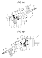
- FIG. 1A and FIG. 1B are used to describe an external configuration of a rotating electrical machine 1 having a rotating electrical machine cable, according to the present embodiment.
- FIG. 1A is a top view of the rotating electrical machine 1 having a rotating electrical machine cable drawn to the load side 10A (hereafter, referred to as "load side drawn cable 10A").
- FIG. 1B is a top view of the rotating electrical machine 1 having a rotating electrical machine cable drawn to the anti-load side 10B (hereafter, referred to as "anti-load side drawn cable 10B").
- load side specifies the direction in which a rotating shaft 6 projects with respect to the rotating electrical machine 1 (the right side in FIG. 1A and FIG. 1B ).
- anti-load side specifies the opposite direction to the load side, that is, the direction in which an encoder cover 5 is arranged with respect to the rotating electrical machine 1 (the left side in FIG. 1A and FIG. 1B ).
- the rotating electrical machine 1 has a cylindrical unit frame 2, an anti-load side bracket 4, a load side bracket 3, and an encoder cover 5.
- the anti-load side bracket 4 is provided to one end in the axial direction of the unit frame 2 (the left side in FIG. 1A and FIG. 1B ).
- the load side bracket 3 is provided to the other end in the axial direction of the unit frame 2 (the right side in FIG. 1A and FIG. 1B ).
- the encoder cover 5 is provided to one end in the axial direction of the anti-load side bracket 4.
- stator and rotor within the unit frame 2. The stator and the rotor are arranged opposed to each other with a magnetic gap in the radial direction.
- the rotating shaft 6 mounted to the rotor is supported by the load side bracket 3 and the anti-load side bracket 4 in a rotatable manner via a not-shown bearing.
- the encoder cover 5 covers a not-shown encoder provided to the anti-load side end of the rotating shaft 6.
- the load side drawn cable 10A has one cable unit 11A, a branching tube 12A (a branching member), a power side connector case 14 (a rotating electrical machine side connector case), an encoder side connector case 16, a power side connector 13 (a rotating electrical machine side connector), and an encoder side connector 15.
- the cable unit 11A is arranged between the rotating electrical machine 1 having an encoder (not shown) and a control apparatus (not shown).
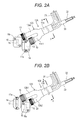
- the branching tube 12A is connected to one end of the cable unit 11A (the left side in FIG. 1A and FIG. 2A ).
- the power side connector case 14 and the encoder side connector case 16 are connected in parallel to each other to one end of the cable unit 11A via the branching tube 12A.
- the power side connector 13 is accommodated in the power side connector case 14.
- the encoder side connector 15 is accommodated in the encoder side connector case 16.
- the term "connected in parallel” refers to the situation that the power side connector case 14 and the encoder side connector case 16 are connected to one end of the one cable unit 11A by forked cable structure.
- the load side drawn cable 10A is configured to be drawn to the load side with the attitude inclined with respect to the axial direction of the rotating shaft 6.
- the load side drawn cable 10A is not limited to the above, but may be configured to be drawn to the load side with the attitude parallel to the axial direction, for example.
- the branching tube 12A is made of a flexible waterproof material such as a rubber, a resin, or the like.
- the branching tube 12A has two branching parts 12a1 and 12a2.
- the branching tube 12A is configured such that the lengths of the two branching parts 12a1 and 12a2 are different to each other.
- the branching tube 12A is configured such that the branching part 12a2 is longer than the branching part 12a1.
- a plurality of (four, in this example) power side cables 31 (the rotating electrical machine side cable) branched from the cable unit 11A is wired.
- a plurality of (six, in this example) encoder side cables 32 branched from the cable unit 11A is wired.
- the power side connector case 14 is connected to the one branching part 12a1 of the branching tube 12A via a coupling 19.
- the power side connector 13 accommodated in the power side connector case 14 is connected to the power side cables 31 wired within the branching part 21a1.
- the encoder side connector case 16 is connected to the other branching part 12a2 of the branching tube 12A via a coupling 20.
- the encoder side connector 15 accommodated in the encoder side connector case 16 is connected to the encoder side cables 32 wired within the branching part 12a2.
- the anti-load side bracket 4 is provided with not-shown connection terminals of the rotating electrical machine 1 (the connection terminals for power supply to the coil winding mounted to the stator and for frame grounding).
- the power side connector 13 is connected to these connection terminals.
- the power side connector case 14 accommodates the power side connector 13 so as to cover it from the upper side.
- the power side connector case 14 is fixed to the anti-load side bracket 4 via screws 17 inserted through screw holes 17a provided in two positions at both ends of the power side connector case 14.
- the encoder cover 5 is provided with not-shown connection terminals of the encoder (the connection terminals for power supply to the encoder and for signaling).
- the encoder side connector 15 is connected to these connection terminals.
- the encoder side connector case 16 accommodates the encoder side connector 15 so as to cover it from the upper side.
- the encoder side connector case 16 is fixed to the encoder cover 5 via screws 18 inserted through screw holes 18a provided in two positions at both ends in the diagonal direction of the encoder side connector case 16.
- FIG. 1A and FIG. 2A the other sides of the power side cables 31 and the encoder side cables 32 are illustrated as if they were exposed and loosen out of the cable unit 11A for the purpose of illustration of the cable arrangement. In the actual implementation, however, the power side cables 31 and the encoder side cables 32 are not exposed in the middle of the cable unit 11A.
- the other end of the cable unit 11A is provided with the branching structure similar to one end of the cable unit 11.
- the other ends of the respective connectors of the power side cables 31 and the encoder side cables 32 are connected to the not-shown control apparatus.
- the anti-load side drawn cable 10B has one cable unit 11B, a branching tube 12B (a branching member), a power side connector case 14, an encoder side connector case 16, a power side connector 13, and an encoder side connector 15.
- the branching tube 12B is connected to one end of the cable unit 11B (the right side in FIG. 1B and the left side in FIG. 2B ).
- the power side connector case 14 and the encoder side connector case 16 are connected in parallel to each other to one end of the cable unit 11B via the branching tube 12B.
- the power side connector 13 is accommodated in the power side connector case 14.
- the encoder side connector 15 is accommodated in the encoder side connector case 16.
- the anti-load side drawn cable 10B is configured to be drawn to the anti-load side with the attitude inclined with respect to the axial direction of the rotating shaft 6.
- the anti-load side drawn cable 10B is not limited to the above, but may be configured to be drawn to the anti-load side with the attitude parallel to the axial direction, for example.
- the branching tube 12B is made of a flexible waterproof material such as a rubber, a resin, or the like.
- the branching tube 12B has two branching parts 12b1 and 12b2.
- the branching tube 12B is configured such that the lengths of the two branching parts 12b1 and 12b2 are different to each other.
- the branching tube 12B is configured such that the branching part 12b1 is longer than the branching part 12b2.
- a plurality of (four, in this example) power side cables 31 branched from the cable unit 11B is wired.
- a plurality of (six, in this example) encoder side cables 32 branched from the cable unit 11B is wired.
- the power side connector case 14 is connected to the one branching part 12b1 of the branching tube 12B via a coupling 19.
- the power side connector 13 accommodated in the power side connector case 14 is connected to the power side cables 31 wired within the branching part 21b1.
- the encoder side connector case 16 is connected to the other branching part 12b2 of the branching tube 12B via a coupling 20.
- the encoder side connector 15 accommodated in the encoder side connector case 16 is connected to the encoder side cables 32 wired within the branching part 12b2.
- connection of the power side connector 13 to the connection terminals of the rotating electrical machine 1, the fixation of the power side connector case 14 to the anti-load side bracket 4, the connection of the encoder side connector 15 to the connection terminals of the encoder, the fixation of the encoder side connector case 16 to the encoder cover 5, and so on in the anti-load side drawn cable 10B are the same as those in the load side drawn cable 10A.
- FIG. 3 illustrates the internal configuration of the cable units 11A and 11B.
- the cable units 11A and 11B have therein the plurality of (six, in this example) encoder side cables 32 and the plurality of (four, in this example) power side cables 31.
- the plurality of encoder side cables 32 has relatively thick cables 32a for the power supply to the encoder and relatively thin cables 32b for the signaling to the encoder.
- encoder side cables 32a and the encoder side cables 32b are not distinguished in particular, these are referred to as simply "encoder side cables 32".
- the plurality of encoder side cables 32 is covered with a shield material 33 for suppressing penetration of an electromagnetic wave.
- the encoder side cables 32 may be configured such that the plurality of encoder side cables 32 is covered with a sheath 35 (see FIG. 5A and FIG. 5B described later) arranged in the outer peripheral side of the shield material 33, though the depiction is omitted here.
- the rotating electrical machine cable 10 of the present embodiment is the cable used for wiring between the rotating electrical machine 1 having the encoder and the control apparatus.
- the rotating electrical machine cable 10 has one cable unit 11, and the power side connector case 14 and the encoder side connector case 16 that are connected to one end of the cable unit 11.
- the power side connector 13 accommodated in the power side connector case 14 is connected to the rotating electrical machine 1.
- the encoder side connector 15 accommodated in the encoder side connector case 16 is connected to the encoder.
- the rotating electrical machine cable 10 of the present embodiment is configured as one cable. Therefore, the rotating electrical machine cable 10 allows for the improvement of the handleability when wiring cables compared to the case where two cables are used for wiring from each of the rotating electrical machine 1 and the encoder to the control apparatus. Further, the operation such as the bundling of the two cables when wiring is no longer necessary. This allows for the reduction in the workload.
- both of the power side connector 13 and the encoder side connector 15 are accommodated in the connector cases 14 and 16, respectively. Therefore, the waterproof and dustproof structure can be provided to the connection parts of the connectors 13 and 15.
- the power side connector case 14 and the encoder side connector case 16 are connected in parallel to each other to one end of the cable unit 11. Thereby, the flexibility in the arrangement of the power side connector 13 and the encoder side connector 15 can be enhanced with the gap between both cases 14 and 16 being increased or decreased and the like.
- the rotating electrical machine cable 10 has the branching tube 12 connected to one end of the cable unit 11.
- the branching tube 12A (or the branching tube 12B, hereafter, the same relationship will apply) has two branching parts 12a1 and 12a2 (or branching parts 12b1 and 12b2).
- One branching part 12a1 (or 12b1) is connected with the power side connector case 14.
- the other branching part 12a2 (or 12b2) is connected with the encoder side connector case 16.
- the branching tube 12A is configured such that the length of one branching part 12a1 and that of the other branching part 12a2 are different to each other.
- each of the branching tubes 12A and 12B is configured such that the length of the two branching parts are different to each other, as described above. That is, in the load side drawn cable 10A, the other branching part 12a2 of the branching tube 12A is longer than the one branching part 12a1. Further, in the anti-load side drawn cable 10B, the one branching part 12b1 of the branching tube 12B is longer than the other branching part 12b2.
- branching parts 12a1 and 12a2 of the branching tube 12A and the branching parts 12b1 and 12b2 of the branching tube 12B correspond an example of the means for distinguishing directions in which the cable is drawn from the rotating electrical machine and the encoder.
- the cable unit 11 has therein the encoder side cables 32 and the power side cables 31 arranged in the outer peripheral side of the encoder side cables 32.
- the encoder side cables 32 that are likely to be affected by noise are arranged in the inner circumference side of the power side cables 31. Thereby, the affection by the external noise to the encoder side cables 32 can be reduced.
- the shield material 33 is arranged between the encoder side cables 32 and the power side cables 31. Thereby, the affection by the noise from the power side cables 31 to the encoder side cables 32 can also be reduced.
- the relatively thick power side cables 31 are arranged in the outer peripheral side of the relatively thin encoder side cables 32. This allows for a thinner cable unit 11 compared to the case of the opposite arrangement.
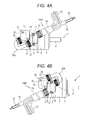
- FIG. 4A and FIG. 4B illustrate an example of the present modified example.
- FIG. 4A is a top view of the rotating electrical machine 1 having a rotating electrical machine cable drawn to the load side 10A1 (hereafter, referred to as "load side drawn cable 10A1").
- FIG. 4B is a top view of the rotating electrical machine 1 having a rotating electrical machine cable drawn to the anti-load side 10B1 (hereafter, referred to as "anti-load side drawn cable 10B1").
- the same members as those in FIG. 1A and FIG. 1B are provided with the same reference numerals and description thereof will be properly omitted or simplified.
- the load side drawn cable 10A1 has a connection tube 22A connecting the power side connector case 14 to the encoder side connector case 16, as illustrated in FIG. 4A .
- the connection tube 22A is made of a flexible waterproof material such as a rubber, a resin, or the like.
- the cable unit 11A is connected to the power side connector case 14 via the coupling 19. That is, the power side connector case 14 is arranged between the cable unit 11A and the encoder side connector case 16.
- the power side connector 13 accommodated in the power side connector case 14 is connected to a plurality of (four, in this example) power side cables 31 wired within the cable unit 11A.
- connection tube 22A One end of the connection tube 22A is connected to the power side connector case 14 via the coupling 21. The other end of the connection tube 22A is connected to the encoder side connector case 16 via the coupling 20.
- a plurality of (six, in this example) encoder side cables 32 is wired. These encoder side cables 32, within the power side connector case 14, are guided from the cable unit 11A so as to circumvent the power side connector 13. These encoder side cables 32 are connected to the encoder side connector 15 accommodated in the encoder side connector case 16.
- the anti-load side drawn cable 10B1 has a connection tube 22B connecting the power side connector case 14 to the encoder side connector case 16, as illustrated in FIG. 4B .
- the connection tube 22B is made of a flexible waterproof material such as a rubber, a resin, or the like.
- the cable unit 11B is connected to the power side connector case 14 via the coupling 19. That is, the power side connector case 14 is arranged between the cable unit 11B and the encoder side connector case 16.
- the power side connector 13 accommodated in the power side connector case 14 is connected to a plurality of (four, in this example) power side cables 31 wired within the cable unit 11B.
- connection tube 22B One end of the connection tube 22B is connected to the power side connector case 14 via the coupling 21. The other end of the connection tube 22B is connected to the encoder side connector case 16 via the coupling 20.
- a plurality of (six, in this example) encoder side cables 32 is wired. These encoder side cables 32, within the power side connector case 14, are guided from the cable unit 11B so as to circumvent the power side connector 13. These encoder side cables 32 are connected to the encoder side connector 15 accommodated in the encoder side connector case 16. It is noted that the internal structure of the cable units 11A and 11B is the same as that of the above-described embodiment.
- connection tube 22 when the load side drawn cable 10A1 and the anti-load side drawn cable 10B1 are not distinguished in particular, these are referred to as simply "rotating electrical machine cable 10" similarly to the embodiment described above. Further, when the connection tubes 22A and 22B are not distinguished in particular, these are referred to as simply "connection tube 22".
- the power side connector case 14 and the encoder side connector case 16 are connected in series to each other to one end of the cable unit 11. Since this eliminates the need for the branching structure, the structure can be simplified. Further, the rotating electrical machine cable 10 can be configured as one cable over its entirety. Thus, the rotating electrical machine cable 10 can be thinner compared to the configuration of the parallel connection as in the above-described embodiment.
- connection tube 22 connecting both connector cases 14 and 16 is thus guided curved to a large extent.
- the cables wired within the connection tube 22 would be the relatively thick power side cables 31. This would make it difficult to guide the connection tube 22.
- the power side connector case 14 is arranged between the cable unit 11 and the encoder side connector case 16. That is, in the rotating electrical machine cable 10, the power side connector case 14 and the encoder side connector case 16 are arranged in series to each other such that the encoder side connector case 16 is arranged in the front end.
- the cables wired within the connection tube 22 are the relatively thin encoder side cables 32. This makes it easier to guide the connection tube 22. Therefore, the handleability when wiring the cables (the connection tube 22) can be improved.
- the rotating electrical machine cable 10 is not limited to it.
- the rotating electrical machine cable 10 may be configured such that the power side connector case 14 is arranged in the front end.
- connection tube 22 may not be necessarily provided.
- the rotating electrical machine cable 10 may be configured such that the plurality of the encoder side cables 32 is covered with the shield material 33 and the sheath 35 in the outer peripheral side thereof (see FIG. 5A and FIG. 5B described later), and may not have the connection tubes 22.
- the power side connector case 14 and the encoder side connector case 16 may be connected by the sheath 35 within which the encoder side cables 32 are wired.
- branching tube is configured such that the encoder side cables are exposed
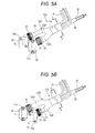
- FIG. 5A and FIG. 5B illustrate an example of the present modified example. It is noted that, in FIG. 5A and FIG. 5B , the same parts as those in the above-described FIG. 2A and FIG. 2B are provided with the same reference numerals and description thereof will be properly omitted.
- the branching tube 12A' of the load side drawn cable 10A has two branching parts 12a1 and 12a2 in the present modified example.
- the branching part 12a2 is formed shorter than that in the embodiment illustrated in FIG. 2A and FIG. 2B .
- the encoder side cables 32 are thus exposed.
- the plurality of the encoder side cables 32 is covered with the shield material 33 (depiction is omitted in FIG. 5A and FIG. 5B ) and the sheath 35 in the outer peripheral side thereof.
- the sheath 35 is made of the material having an insulating property, a waterproof property, and the like. It is noted that the configuration of the branching part 12a1 side is the same as that in the embodiment illustrated in FIG. 2A .
- the branching tube 12B' of the anti-load side drawn cable 10B has the same configuration as the above. That is, the branching part 12b2 is formed relatively shorter, and the sheath 35 of the encoder side cables 32 is exposed.
- the cable unit 11 is configured such that the power side cables 31 are arranged in the outer peripheral side of the encoder side cables 32. Without limited to it and contrary to it, however, the cable unit 11 may be configured such that the encoder side cables 32 are arranged in the outer peripheral side of the power side cables 31.
- parallel in the above description may not be the parallel in the strict sense. That is, the term “parallel” refers to “substantially parallel”, which permits the tolerance and error in the design and manufacturing.
- rotating electrical machine cable may be the following first and second rotating electrical machine cables.
- the first rotating electrical machine cable is a rotating electrical machine cable used for wiring between a rotating electrical machine having an encoder and a control apparatus, and the cable has one cable unit, a rotating electrical machine side connector case for accommodating a rotating electrical machine side connector connected to one end of the cable unit and connected to the rotating electrical machine, and an encoder side connector case for accommodating an encoder side connector connected to one end of the cable unit and connected to the encoder.
- the second rotating electrical machine cable is a rotating electrical machine cable used for wiring between a rotating electrical machine having an encoder and a control apparatus, and the cable has one cable unit, a rotating electrical machine side connector case for accommodating a rotating electrical machine side connector connected to one end of the cable unit and connected to the rotating electrical machine, an encoder side connector case for accommodating an encoder side connector connected to one end of the cable unit and connected to the encoder, and means for distinguishing directions in which the cable is drawn from the rotating electrical machine and the encoder.
Landscapes
- Engineering & Computer Science (AREA)
- Power Engineering (AREA)
- Motor Or Generator Frames (AREA)
- Transmission And Conversion Of Sensor Element Output (AREA)
- Insulated Conductors (AREA)
Applications Claiming Priority (1)
| Application Number | Priority Date | Filing Date | Title |
|---|---|---|---|
| JP2013238601A JP5939511B2 (ja) | 2013-11-19 | 2013-11-19 | 回転電機 |
Publications (2)
| Publication Number | Publication Date |
|---|---|
| EP2874284A2 true EP2874284A2 (fr) | 2015-05-20 |
| EP2874284A3 EP2874284A3 (fr) | 2016-08-03 |
Family
ID=51900260
Family Applications (1)
| Application Number | Title | Priority Date | Filing Date |
|---|---|---|---|
| EP14193174.1A Withdrawn EP2874284A3 (fr) | 2013-11-19 | 2014-11-14 | Câble de machine électrique rotative |
Country Status (4)
| Country | Link |
|---|---|
| US (1) | US20150137640A1 (fr) |
| EP (1) | EP2874284A3 (fr) |
| JP (1) | JP5939511B2 (fr) |
| CN (1) | CN104658645B (fr) |
Families Citing this family (2)
| Publication number | Priority date | Publication date | Assignee | Title |
|---|---|---|---|---|
| CN106205380A (zh) * | 2016-08-31 | 2016-12-07 | 无锡市万里实业发展有限公司 | 在线卫生系统显示装置 |
| JP7267555B2 (ja) * | 2019-01-31 | 2023-05-02 | ニデックインスツルメンツ株式会社 | モータ |
Citations (1)
| Publication number | Priority date | Publication date | Assignee | Title |
|---|---|---|---|---|
| JP2008191874A (ja) | 2007-02-02 | 2008-08-21 | Yaskawa Electric Corp | 配線確認システム |
Family Cites Families (12)
| Publication number | Priority date | Publication date | Assignee | Title |
|---|---|---|---|---|
| JPS52154682U (fr) * | 1976-05-19 | 1977-11-24 | ||
| JP2002313144A (ja) * | 2001-04-09 | 2002-10-25 | Omron Corp | サーボモータシステム |
| JP3774130B2 (ja) * | 2001-06-19 | 2006-05-10 | 矢崎総業株式会社 | ワイヤハーネス |
| JP2003275985A (ja) * | 2002-03-25 | 2003-09-30 | Nachi Fujikoshi Corp | 産業用ロボットのモータユニット |
| DE10334655A1 (de) * | 2003-07-22 | 2005-03-03 | ITT Manufacturing Enterprises, Inc. (n.d.Ges.d. Staates Delaware), Wilmington | Steckverbindervorrichtung für Kleinservomotoren |
| JP2005174597A (ja) * | 2003-12-08 | 2005-06-30 | Fuji Xerox Co Ltd | ワイヤーハーネス接続構造 |
| JP4967817B2 (ja) * | 2007-05-29 | 2012-07-04 | トヨタ自動車株式会社 | 回転電機用端子台 |
| JP2010177112A (ja) * | 2009-01-30 | 2010-08-12 | Mabuchi Motor Co Ltd | コネクタ組立部構造及び該構造を有する減速機付モータ |
| CN201477943U (zh) * | 2009-07-28 | 2010-05-19 | 无锡市沪安电线电缆有限公司 | 隧道照明专用电缆 |
| US7871293B1 (en) * | 2009-09-08 | 2011-01-18 | John Chung | Bi-directional audio cable assembly |
| TWI398053B (zh) * | 2010-04-09 | 2013-06-01 | Via Tech Inc | 纜線組與電子裝置 |
| US9287703B2 (en) * | 2012-04-30 | 2016-03-15 | Drs Sustainment Systems, Inc. | Generalized system architecture for peripheral connectivity and control |
-
2013
- 2013-11-19 JP JP2013238601A patent/JP5939511B2/ja active Active
-
2014
- 2014-11-14 EP EP14193174.1A patent/EP2874284A3/fr not_active Withdrawn
- 2014-11-14 CN CN201410647329.7A patent/CN104658645B/zh active Active
- 2014-11-18 US US14/543,955 patent/US20150137640A1/en not_active Abandoned
Patent Citations (1)
| Publication number | Priority date | Publication date | Assignee | Title |
|---|---|---|---|---|
| JP2008191874A (ja) | 2007-02-02 | 2008-08-21 | Yaskawa Electric Corp | 配線確認システム |
Also Published As
| Publication number | Publication date |
|---|---|
| JP5939511B2 (ja) | 2016-06-22 |
| JP2015100190A (ja) | 2015-05-28 |
| CN104658645B (zh) | 2017-01-18 |
| CN104658645A (zh) | 2015-05-27 |
| EP2874284A3 (fr) | 2016-08-03 |
| US20150137640A1 (en) | 2015-05-21 |
Similar Documents
| Publication | Publication Date | Title |
|---|---|---|
| KR102353916B1 (ko) | 터미널 어셈블리 및 이를 포함하는 모터 | |
| KR101957042B1 (ko) | 모터 | |
| EP2855211B1 (fr) | Faisceau électrique avec éléments de fixation | |
| CN112740495B (zh) | 线束 | |
| EP3057182B1 (fr) | Connecteur avec adaptateur de conduit pré-assemblé | |
| US10491151B2 (en) | Noise filter, circuit substrate, and power converter | |
| KR102296565B1 (ko) | 3축 짐벌 및 3축 짐벌 촬영장치 | |
| EP2874284A2 (fr) | Câble de machine électrique rotative | |
| US20160126793A1 (en) | Structure for Preventing Scattering of Magnet and Retaining Magnet for Rotating Electrical Machine | |
| CN112531427B (zh) | 用于复合电缆的中继装置 | |
| CN109769403B (zh) | 后保持件和包括该后保持件的马达 | |
| US11799351B2 (en) | Motor | |
| JP5333871B2 (ja) | 回転電機 | |
| WO2015083478A1 (fr) | Machine électrique tournante | |
| CN115244793A (zh) | 线缆夹具及电动机 | |
| JP7517195B2 (ja) | ワイヤハーネス | |
| JPWO2020121529A1 (ja) | 電動機 | |
| EP3522318A1 (fr) | Mécanisme d'enroulement de câble | |
| EP2717390B1 (fr) | Connecteur | |
| KR102371383B1 (ko) | 모터의 터미널 조립체 및 이를 포함하는 모터 | |
| US9948052B2 (en) | Method for routing a conductor across a terminal block | |
| JP2000040552A (ja) | 多極コネクタケーブル | |
| EP4020723A1 (fr) | Dispositif de connecteur rotatif et ensemble câble plat pour dispositif de connecteur rotatif | |
| JP2019068682A (ja) | 導線部材および駆動ユニット | |
| CN119448636A (zh) | 马达 |
Legal Events
| Date | Code | Title | Description |
|---|---|---|---|
| PUAI | Public reference made under article 153(3) epc to a published international application that has entered the european phase |
Free format text: ORIGINAL CODE: 0009012 |
|
| 17P | Request for examination filed |
Effective date: 20141114 |
|
| AK | Designated contracting states |
Kind code of ref document: A2 Designated state(s): AL AT BE BG CH CY CZ DE DK EE ES FI FR GB GR HR HU IE IS IT LI LT LU LV MC MK MT NL NO PL PT RO RS SE SI SK SM TR |
|
| AX | Request for extension of the european patent |
Extension state: BA ME |
|
| PUAL | Search report despatched |
Free format text: ORIGINAL CODE: 0009013 |
|
| AK | Designated contracting states |
Kind code of ref document: A3 Designated state(s): AL AT BE BG CH CY CZ DE DK EE ES FI FR GB GR HR HU IE IS IT LI LT LU LV MC MK MT NL NO PL PT RO RS SE SI SK SM TR |
|
| AX | Request for extension of the european patent |
Extension state: BA ME |
|
| RIC1 | Information provided on ipc code assigned before grant |
Ipc: H02K 5/22 20060101AFI20160627BHEP |
|
| STAA | Information on the status of an ep patent application or granted ep patent |
Free format text: STATUS: THE APPLICATION IS DEEMED TO BE WITHDRAWN |
|
| 18D | Application deemed to be withdrawn |
Effective date: 20170204 |