EP3057182B1 - Connecteur avec adaptateur de conduit pré-assemblé - Google Patents
Connecteur avec adaptateur de conduit pré-assemblé Download PDFInfo
- Publication number
- EP3057182B1 EP3057182B1 EP15154926.8A EP15154926A EP3057182B1 EP 3057182 B1 EP3057182 B1 EP 3057182B1 EP 15154926 A EP15154926 A EP 15154926A EP 3057182 B1 EP3057182 B1 EP 3057182B1
- Authority
- EP
- European Patent Office
- Prior art keywords
- shell
- electrical connector
- connector assembly
- conduit adapter
- latching
- Prior art date
- Legal status (The legal status is an assumption and is not a legal conclusion. Google has not performed a legal analysis and makes no representation as to the accuracy of the status listed.)
- Active
Links
Images


Classifications
-
- H—ELECTRICITY
- H01—ELECTRIC ELEMENTS
- H01R—ELECTRICALLY-CONDUCTIVE CONNECTIONS; STRUCTURAL ASSOCIATIONS OF A PLURALITY OF MUTUALLY-INSULATED ELECTRICAL CONNECTING ELEMENTS; COUPLING DEVICES; CURRENT COLLECTORS
- H01R13/00—Details of coupling devices of the kinds covered by groups H01R12/70 or H01R24/00 - H01R33/00
- H01R13/46—Bases; Cases
- H01R13/502—Bases; Cases composed of different pieces
- H01R13/506—Bases; Cases composed of different pieces assembled by snap action of the parts
-
- H—ELECTRICITY
- H01—ELECTRIC ELEMENTS
- H01R—ELECTRICALLY-CONDUCTIVE CONNECTIONS; STRUCTURAL ASSOCIATIONS OF A PLURALITY OF MUTUALLY-INSULATED ELECTRICAL CONNECTING ELEMENTS; COUPLING DEVICES; CURRENT COLLECTORS
- H01R13/00—Details of coupling devices of the kinds covered by groups H01R12/70 or H01R24/00 - H01R33/00
- H01R13/46—Bases; Cases
- H01R13/50—Bases; Cases formed as an integral body
- H01R13/501—Bases; Cases formed as an integral body comprising an integral hinge or a frangible part
-
- H—ELECTRICITY
- H01—ELECTRIC ELEMENTS
- H01R—ELECTRICALLY-CONDUCTIVE CONNECTIONS; STRUCTURAL ASSOCIATIONS OF A PLURALITY OF MUTUALLY-INSULATED ELECTRICAL CONNECTING ELEMENTS; COUPLING DEVICES; CURRENT COLLECTORS
- H01R13/00—Details of coupling devices of the kinds covered by groups H01R12/70 or H01R24/00 - H01R33/00
- H01R13/46—Bases; Cases
- H01R13/502—Bases; Cases composed of different pieces
-
- H—ELECTRICITY
- H01—ELECTRIC ELEMENTS
- H01R—ELECTRICALLY-CONDUCTIVE CONNECTIONS; STRUCTURAL ASSOCIATIONS OF A PLURALITY OF MUTUALLY-INSULATED ELECTRICAL CONNECTING ELEMENTS; COUPLING DEVICES; CURRENT COLLECTORS
- H01R13/00—Details of coupling devices of the kinds covered by groups H01R12/70 or H01R24/00 - H01R33/00
- H01R13/56—Means for preventing chafing or fracture of flexible leads at outlet from coupling part
- H01R13/562—Bending-relieving
-
- H—ELECTRICITY
- H01—ELECTRIC ELEMENTS
- H01R—ELECTRICALLY-CONDUCTIVE CONNECTIONS; STRUCTURAL ASSOCIATIONS OF A PLURALITY OF MUTUALLY-INSULATED ELECTRICAL CONNECTING ELEMENTS; COUPLING DEVICES; CURRENT COLLECTORS
- H01R13/00—Details of coupling devices of the kinds covered by groups H01R12/70 or H01R24/00 - H01R33/00
- H01R13/58—Means for relieving strain on wire connection, e.g. cord grip, for avoiding loosening of connections between wires and terminals within a coupling device terminating a cable
- H01R13/5804—Means for relieving strain on wire connection, e.g. cord grip, for avoiding loosening of connections between wires and terminals within a coupling device terminating a cable comprising a separate cable clamping part
- H01R13/5812—Means for relieving strain on wire connection, e.g. cord grip, for avoiding loosening of connections between wires and terminals within a coupling device terminating a cable comprising a separate cable clamping part the cable clamping being achieved by mounting the separate part on the housing of the coupling device
-
- H—ELECTRICITY
- H01—ELECTRIC ELEMENTS
- H01R—ELECTRICALLY-CONDUCTIVE CONNECTIONS; STRUCTURAL ASSOCIATIONS OF A PLURALITY OF MUTUALLY-INSULATED ELECTRICAL CONNECTING ELEMENTS; COUPLING DEVICES; CURRENT COLLECTORS
- H01R13/00—Details of coupling devices of the kinds covered by groups H01R12/70 or H01R24/00 - H01R33/00
- H01R13/58—Means for relieving strain on wire connection, e.g. cord grip, for avoiding loosening of connections between wires and terminals within a coupling device terminating a cable
- H01R13/582—Means for relieving strain on wire connection, e.g. cord grip, for avoiding loosening of connections between wires and terminals within a coupling device terminating a cable the cable being clamped between assembled parts of the housing
-
- H—ELECTRICITY
- H01—ELECTRIC ELEMENTS
- H01R—ELECTRICALLY-CONDUCTIVE CONNECTIONS; STRUCTURAL ASSOCIATIONS OF A PLURALITY OF MUTUALLY-INSULATED ELECTRICAL CONNECTING ELEMENTS; COUPLING DEVICES; CURRENT COLLECTORS
- H01R43/00—Apparatus or processes specially adapted for manufacturing, assembling, maintaining, or repairing of line connectors or current collectors or for joining electric conductors
-
- H—ELECTRICITY
- H01—ELECTRIC ELEMENTS
- H01R—ELECTRICALLY-CONDUCTIVE CONNECTIONS; STRUCTURAL ASSOCIATIONS OF A PLURALITY OF MUTUALLY-INSULATED ELECTRICAL CONNECTING ELEMENTS; COUPLING DEVICES; CURRENT COLLECTORS
- H01R13/00—Details of coupling devices of the kinds covered by groups H01R12/70 or H01R24/00 - H01R33/00
- H01R13/62—Means for facilitating engagement or disengagement of coupling parts or for holding them in engagement
- H01R13/627—Snap or like fastening
Definitions
- the present invention relates to conduit adapter systems comprising a conduit adapter that is assigned to an electrical connector assembly.
- Conduit adapters are commonly used to protect electrical cables that enter or exit an electrical connector assembly. In particular the cables are protected from environmental influences, such as temperature, dust, moisture and/or the like. Still further conduit adapters can provide strain relief functionality and/or protect the cables from unallowed cable bending and thus prevent cable damages. Conduit adapters can provide connecting means between cable channels, and in particular flexible cable channels and electrical connector assemblies. Conduit adapters are for example widely used in automobile applications, industrial applications and/or consumer electronic applications. Document JP2008293810 disclose a conduit adapter according the preamble of the current invention.
- Conduit adapter systems known in the art typically comprise two separate parts that can be connected together to form the conduit adapter around the cable to be protected. Providing a two-part adapter allows the conduit adapter to be installed after the installation of the connector and the respective cable. However, in an industrial manufacturing process two separate parts are undesired, since the number of individual parts increases the complexity of the manufacturing process and in particular the supply process of the parts.
- the single parts of known conduit adapters are usually connected via a hinge, so that only one physical part has to be handled in the supply process.
- Known hinges are orientated at a longitudinal axis at the sides of the parts of the conduit adapter. This allows the parts to be rotated around an axis parallel to the cables of the electrical connector assembly, when the parts shall be connected.
- providing a hinge at the longitudinal axis, i.e. at the sides of the parts is disadvantageous, since there is less space to provide fixing means.
- the fixing means on the hinge-side have to be designed smaller and therefore weaker, than the fixing means on the non-hinge-side of a conventional conduit adapter.
- connection between electrical connector system and conduit adapter is typically achieved by clamping or engaging the electrical conductor system when the two parts of the conduit adapter are connected.
- the object of the present invention is to provide conduit adapter systems and a method to assemble said conduit adapter systems, which overcomes the problems and drawbacks described above.
- a conduit adapter system comprising a conduit adapter being assigned to an electrical connector assembly, whereby the conduit adapter comprises a first shell and a second shell.
- the first shell of the conduit adapter comprises at least one first fixing element and the second shell of the conduit adapter comprises at least one corresponding second fixing element, so that the first and second shell can be fixed together.
- the first shell comprises at least one pre-locking means that can be engaged with corresponding pre-locking means of the electrical connector assembly, to lock the first shell to the electrical connector assembly in a pre-assembled condition.
- a first and/ or second fixing element can be any kind of element that is suitable to fix the first and second shell together in a releasable or permanent manner, such as screws, bolts, rivets, pins, clamps and/or the like.
- a combination of different fixing elements is also possible.
- the first shell of the conduit adapter can be pre-locked to the electrical connector assembly to arrive at the preassembled condition.
- the shell is securely (pre-)attached to the connector assembly, so than an operator can use both hands to e.g. arrange the cables of the connector and to fix the second shell to the first shell. It is thus advantageously no longer necessary to hold the shell(s) manually.
- the pre-locking means can be any kind of means that is suitable to provide a releasable or permanent connection between the first shell of the conduit adapter and the electrical connector assembly, such as screws, bolts, rivets, pins, clamps, adhesives and/or the like.
- At least one pre-locking means of the first shell and the corresponding pre-locking means of the electrical connector assembly can be formed as latching protrusions and corresponding latching recesses.
- a latching connection that is achieved by engaging at least one latching protrusion and a corresponding latching recess is advantageous, since those latching connections can be locked rapidly and preferably without the use of additional tools.
- the latching protrusion can either be formed on the first shell of the conduit adapter or on the electrical connector assembly.
- first shell of the conduit adapter comprises a first groove that can be engaged with a first collar of the electrical connector assembly in the pre-assembled condition.
- Said first groove increases the mechanical stability of the connection between the conduit adapter and the electrical connector assembly, particularly in axial direction of the cables of the electrical connector assembly, when it is engaged with the first collar of the electrical connector assembly.
- the combination of groove and collar can provide sealing functionality and prevent the penetration of moisture and contaminants in the conduit adapter.
- the collar and the groove facilitate the orientation of the first shell to the electrical connector assembly during the locking of the pre-locking means, and therefore allow a fast pre-locking.
- the at least one pre-locking means of the first shell is formed as a latching protrusion.
- the at least one pre-locking means of the first shell is arranged in the first groove, and the corresponding pre-locking means of the electrical connector assembly is formed as a latching recess that is formed in the first collar of the electrical connector assembly.
- the second shell comprises a second groove that can be engaged with a second collar of the electrical connector assembly, whereby the second collar is preferably integrally formed with the first collar of the electrical connector assembly.
- the second groove and the second collar are preferably engaged, when the first and second shell are fixed together.
- Providing a second groove and a second collar is advantageous, since the mechanical stability of the connection between the conduit adapter and the electrical connector assembly in particular in axial direction (i.e. in the longitudinal direction of the cables) can be further improved.
- fixing of the second shell to the first shell is facilitated, since the second shell can be guided by the collar and the corresponding second groove in the correct position, even before the fixing elements are fixed to each other.
- a manufacturer has the possibility to monitor the correct position of the first and second shell before the fixing elements are fixed.
- the first shell comprises at least two, and even more preferably four first fixing elements that are formed identical, whereby the second shell comprises corresponding second fixing elements.
- conduit adapter can be assembled with identical fixing-forces on the right hand and left hand side of the adapter.
- latching connections when latching connections are used, the correct connection of the identical latching connections can be easily controlled by the uniform clicking sound of the identical latching connections.
- the first fixing elements and the corresponding second fixing elements are formed as latching recesses and corresponding latching protrusions, and even more preferably as latching hooks and latching noses.
- a latching connection that is achieved by engaging at least one latching protrusion and a corresponding latching recess is advantageous, since those latching connections can be locked rapidly, preferably without the use of additional tools.
- the latching protrusions can be either provided on the first shell or on the second shell. Combinations of latching protrusions and latching recesses on a shell of the conduit adapter are also possible.
- the latching protrusions and latching recesses are arranged in that manner, that the second shell can be positioned relative to the first shell and is guided by the latching elements from an un-latched to a latched condition.
- the fixing of the second shell to the first shell is facilitated.
- the latching hooks are U-shaped.
- a U-shaped hook comprises two legs and a cross bar.
- Such latching hooks are advantageous, since they can provide high latching forces and therefore a strong and secure connection. Still further, the risk of tangling up the latching hook with particularly thin cables to be protected is reduced by using U-shaped hooks.
- the first and second shells are connected via a hinge.
- a hinge is advantageous, since only one physical part, and not two separate shells, has to be handled in the supply process. Still further, a hinge limits the degree of freedoms of the connected parts and therefore facilitates the assembly of the conduit adapter system, since the second shell is guided by the hinge.
- the hinge can be a flexible web, a joint or any suitable connection between the first and second shell that allows the second shell to be moved from a position in the pre-assembled condition to its final position; i.e. when the second shell is fixed to the first shell.
- the hinge that connects the first shell and the second shell is arranged between a first front end of the first shell and a second front end of the second shell.
- the first front end is orientated opposite to the electrical connector assembly in the pre-assembled condition, and the second front end points in the same direction as the first front end, when the first and second shell are fixed together.
- the first and second front ends build together an opening, when the first and second shells are fixed together, which opening encloses at least one cable of the electrical connector assembly.
- the hinge extends in the direction of the cables of the electrical connector assembly.
- no extra space is required for the hinge in the radial direction of the cables.
- This allows the connectors and corresponding conduit adapters to be placed in close proximity to each other.
- the hinge is not provided at the longitudinal axis at the side of the shells, this space is available for fixing elements.
- identical formed fixing elements can be provided at the shells.
- At least one electrical cable of the electrical connector assembly is guided by the conduit adapter.
- the hinge that connects the first shell and the second shell provides an axis of rotation that is essentially perpendicular to the longitudinal direction of the cables of the electrical connector assembly.
- a hinge that provides an axis of rotation that is essentially perpendicular to the longitudinal direction of the cables of the electrical connector assembly and connects the first shell and the second shell of the conduit adapter is advantageous, since the second shell can be moved to the first shell with reduced space requirements on the sides of the conduit adapter, compared to conduit adapters, where the hinge is provided at the side of the shells.
- the hinge provides at least a second axis of rotation that allows moving the second shell in an evasive movement around the cables of the electrical connector assembly. The reduced laterally space requirement allows multiple connectors to be placed in close proximity to each other.
- the hinge is a flexible web that is integrally formed with the first and second shell.
- a flexible web as the hinge is advantageous, since the first and second shell as well as the flexible web can be produced in a single step, for example by means of injection molding.
- the flexible web can be soldered, welded, adhered or fixed in any other suitable way to the first and second shell.
- Such a flexible web allows a rotation of the second shell around an axis perpendicular to the direction of the cables of the electric conduit adapter as described above. Further, such a flexible web also allows torsional movement of the second shell, so that the space requirements during the assembly of the conduit adapter can be reduced, as described above.
- the conduit adapter provides a strain relief and even more preferably the first and/or the second shell provide openings that are suitable to guide a cable strap that fixes the at least one cable of the electrical connector assembly to the first and/or second shell of the conduit adapter.
- a strain relief functionality of the conduit adapter can for example be achieved by protrusions that are provided at the shells of the conduit adapter and which protrusions are orientated inwardly, when the first shell and the second shell are fixed together so that the cables of the electrical connector assembly are clamped by said protrusions.
- a cable strap can be used that is guided through openings provided in the first and/or second shell.
- Providing strain relief functionality is advantageous, since cable or connector damages due to traction and/or bending forces can be reduced.
- the combination of the features of the pre-locking of the first shell to the electrical connector assembly and the openings in one of the first and/or second shell is advantageous, since the cables can be fixed by means of the cable strap to the conduit adapter in the pre-assembled condition. A manufacturer would have to handle only two parts that are easily accessible.
- the conduit adapter system comprises an electrical connector assembly whereby the electrical connector assembly provides at least one pre-locking means.
- the pre-locking means of the electrical connector assembly corresponds to the pre-locking means of the conduit adapter.
- Fig. 1 shows a preferred embodiment of the conduit adapter system 1 in an assembled condition, whereby the conduit adapter 200 is mounted to an electrical connector assembly 100.
- the conduit adapter 200 is mounted to the electrical connector assembly 100 and the first shell 210 of the conduit adapter 200 is fixed to the second shell 220 by fixing elements.
- the fixing elements 211, 212 of the first shell 210 are formed as latching elements, and in particular as latching noses.
- the fixing elements 221 and 222 of the second shell 220 are formed as corresponding fixing elements, namely latching elements and in particular as latching hooks formed in a U-shape.
- the first front end 10 of the first shell 210 is oriented opposite to the electrical connector assembly 100.
- the second front end 20 of the second shell 220 points in the same direction as the first front and 10 in the assembled condition as shown.
- both front ends form an opening that guides the cables 300 of the electrical connector assembly 100.
- the first shell 210 and the second shell 220 are connected via a hinge 230 that is formed as a flexible web and arranged between the first front end 10 and the second front end 20.
- This hinge 230 provides an axis of rotation 30 that is perpendicular to the longitudinal direction of the cables 300 of the electrical connector assembly 100. In the assembled condition shown, the hinge 230 extends in the direction of the cables 300. Further, the cables 300 are fixed to the first shell 210 by means of a cable strap 240.
- Fig. 2 shows the conduit adapter 200 of Fig. 1 from a different perspective so that the other side of the conduit adapter is shown.
- the second shell 220 is fixed to the first shell 210 by fixing elements.
- the fixing elements 213, 214 of the first shell 210 are formed as latching elements, and in particular as latching noses.
- the fixing elements 223 and 224 of the second shell 220 are formed as corresponding fixing elements, namely latching elements and in particular as latching hooks formed in a U-shape.
- the preferred embodiment of the conduit adapter 200 shown in Fig. 1 and Fig.2 provides four identical fixing elements that are formed as latching noses and corresponding U-shaped latching hooks.
- the first shell 210 provides two openings 218, 219 that are suitable to guide a cable strap 240 in order to fix cables to the first shell 210.
- the fixation of the cables 300 to the first shell 210 by means of a cable strap 240 can for example be seen in Fig. 1 .
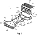
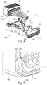
- Figures 3 and 4 show the conduit adapter system 1 of Fig. 1 in an initial condition, whereby the electrical connector assembly 100 is shown without cables in Fig. 3 .
- the conduit adapter 200 is completely separated from the electrical connector assembly 100 and the first shell 210 and the second shell 220 are not fixed together.
- the electrical connector assembly 100 provides a first collar 117 that is engageable with a first groove 217 of the first shell 210 of the conduit adapter 200.
- the electrical connector assembly 100 provides a second collar 127 that is engageable with the second groove of the second shell 220 of the conduit adapter 200.
- the engagement of grooves and collars provides a high mechanical stability of the connection between the electrical connection assembly 100 and the conduit adapter 200 in particular in the axial direction.
- the axial direction is the longitudinal direction of the cables.
- the first shell 210 comprises at least one pre-locking means 215 that is formed as latching protrusion, which is arranged in the first groove 217.
- the pre-locking means 215 can be engaged with the corresponding pre-locking means 115 of the electrical connector assembly 100.
- the corresponding pre-locking means 115 is a latching recess that is formed in the first collar 117 of the electrical connector assembly 100.
- the electrical connector assembly 100 provides a further (second) corresponding pre-locking means 116 that is a latching recess.
- the corresponding pre-locking means 116 can be engaged with a second pre-locking means 216 of the first shell (cf. Fig. 4 ).
- the first shell 210 of the conduit adapters 200 can be locked to the electrical connector assembly 100, to achieve the pre-assembled condition shown in Fig. 6 .
- first shell 210 provides fixing elements 213, 214 that are formed as latching noses.
- the second shell 220 provides corresponding fixing elements 211, 212, 213, 214 that are formed as latching hooks.
- the first shell further provides openings 218, 219 that are suitable to guide a cable strap in order to fix cables to the first shell 210.
- the hinge 230 that connects the first shell 210 with the second shell 220 is a flexible web and is integrally formed with the first 210 and second shell 220.
- the hinge 230 is connected to the first shell 210 at the first front end 10 and provides an axis of rotation 30, that is perpendicular of the direction of the cables 300 (cf. Fig. 4 ) of the electrical connector assembly 100.
- Fig. 5 shows a cut view of the pre-locking means 215 of the first shell 210 of the conduit adapter 200 of Fig. 1 being locked to the corresponding pre-locking means 115 of the electrical connector assembly 100 in the pre-assembled condition.
- the pre-locking means 115, 116 of the first shell 210 are engaged with the corresponding pre-locking means 115, 116 of the electrical connector assembly.
- the pre-locking means 215, 216 is a latching nose that engages with the corresponding latching recess 115, 116 of the electrical connector assembly 100.
- the first collar 117 engages with the first groove 217 of the first shell 210, to provide a high mechanical stability.
- Fig.6 shows the conduit adapter system of Fig. 1 in the pre-assembled condition.
- the first front end 10 of the first shell 210 is oriented opposite to the electrical connector assembly 100.
- the cables 300 are guided by the first shell 210.
- the cables 300 can be fixed to the first shell 210 of the conduit adapter 200 by means of a cable strap 240, as shown.
- the second shell 220 In order to fix the second shell 220 together with the first shell 210, the second shell 220 has to be moved around the cables 300 around an axis 30 perpendicular to the direction of the cables.
- the hinge 230 is sufficiently flexible to allow such a movement.
- the second collar 117 engages the corresponding second groove 127, so that the second shell 220 is guided in the correct axial position, even before the fixing elements are fixed to each other.
- the fixing elements 221, 222, 223, 224 that are formed as U-shaped hooks, guide the second shell in the sideward direction even before the fixing elements are fixed to each other.
Landscapes
- Engineering & Computer Science (AREA)
- Manufacturing & Machinery (AREA)
- Details Of Connecting Devices For Male And Female Coupling (AREA)
Claims (11)
- Système adaptateur pour conduit (1) comprenant un adaptateur pour conduit (200) et un assemblage formant connecteur électrique (100), dans lequel l'assemblage formant connecteur électrique (100) présente au moins un moyen de préblocage (115 ; 116), dans lequel l'adaptateur pour conduit (200) est associé à l'assemblage formant connecteur électrique (100), dans lequel
l'adaptateur pour conduit (200) comprend une première coque (210) et une seconde coque (220), et dans lequel
la première coque (210) comprend au moins un premier élément de fixation (211 ; 212 ; 213 ; 214) et la seconde coque (220) comprend au moins un second élément de fixation correspondant (221 ; 222 ; 223 ; 224) de sorte que la première et la seconde coque peuvent être fixées ensemble, et dans lequel
la première coque (210) comprend au moins un moyen de préblocage (215 ; 216) qui peut être engagé avec le moyen de préblocage correspondant (115 ; 116) de l'assemblage formant connecteur électrique (100), pour bloquer la première coque (210) sur l'assemblage formant connecteur électrique (100) dans une condition préassemblée, caractérisé en ce que
la première coque (210) comprend une première gorge (217) qui peut être engagée avec un premier collier (117) de l'assemblage formant connecteur électrique (100) dans la condition préassemblée, dans lequel ledit au moins un moyen de préblocage (215 ; 216) de la première coque (210) est formé comme une projection de verrouillage qui est agencée dans la première gorge (217), et le moyen de préblocage correspondant (115 ; 116) de l'assemblage formant connecteur électrique (100) est formé comme un évidement de verrouillage qui est formé dans le premier collier (117) de l'assemblage formant connecteur électrique (100). - Système adaptateur pour conduit (1) selon la revendication 1, dans lequel ledit au moins un moyen de préblocage (215 ; 216) de la première coque (210) et le moyen de préblocage correspondant (115 ; 116) de l'assemblage formant connecteur électrique (100) sont formés comme des projections de verrouillage et des évidements de verrouillage correspondants, respectivement.
- Système adaptateur pour conduit selon l'une quelconque des revendications précédentes, dans lequel la seconde coque (220) comprend une seconde gorge (227) qui peut être engagée avec un second collier (127) de l'assemblage formant connecteur électrique (100), et dans lequel le second collier (127) est de préférence formé intégralement avec le premier collier (117) de l'assemblage formant connecteur électrique (100).
- Système adaptateur pour conduit (1) selon l'une quelconque des revendications précédentes, dans lequel la première coque (210) comprend au moins deux, et de préférence quatre premiers éléments de fixation (211, 212, 213, 214) qui sont formés identiques, et dans lequel la seconde coque (220) comprend des seconds éléments de fixation correspondants (221 ; 222 ; 223 ; 224).
- Système adaptateur pour conduit (1) selon l'une quelconque des revendications précédentes, dans lequel les premiers éléments de fixation (211 ; 212 ; 213 ; 214) et les seconds éléments de fixation correspondants (221 ; 222 ; 223 ; 224) sont formés comme des évidements de verrouillage et des projections de verrouillage correspondantes, et de préférence comme des crochets de verrouillage et des ergots de verrouillage.
- Système adaptateur pour conduit (1) selon la revendication 5, dans lequel les crochets de verrouillage sont en forme de U.
- Système adaptateur pour conduit (1) selon l'une quelconque des revendications précédentes, dans lequel la première coque (210) et la seconde coque (200) sont connectées via une charnière (230).
- Système adaptateur pour conduit (1) selon la revendication 7, dans lequel la charnière (230) qui connecte la première coque (210) et la seconde coque (200) est agencée entre une première extrémité frontale (10) de la première coque (210) et une seconde extrémité frontale (20) de la seconde coque (200), et dans lequel la première extrémité frontale (10) est orientée à l'opposé de l'assemblage formant connecteur électrique (100) dans la condition préassemblée, et la seconde extrémité frontale (20) pointe dans la même direction que la première extrémité frontale (10), quand la première coque (210) et la seconde coque (200) sont fixées ensemble.
- Système adaptateur pour conduit (1) selon la revendication 7 ou 8, dans lequel au moins un câble électrique (300) de l'assemblage formant connecteur électrique (100) est guidé par l'adaptateur pour conduit (200), et
dans lequel la charnière (230) qui connecte la première coque (210) et la seconde coque (200) présente un axe de rotation (30) qui est essentiellement perpendiculaire à la direction des câbles de l'assemblage formant connecteur électrique (100). - Système adaptateur pour conduit (1) selon l'une quelconque des revendications 7 à 9, dans lequel la charnière (230) est un voile flexible qui est formé intégralement avec la première coque (210) et la seconde coque (200).
- Système adaptateur pour conduit (1) selon l'une des revendications précédentes, dans lequel l'adaptateur pour conduit (200) est un organe de détente de contrainte, et dans lequel la première coque (210) et/ou la seconde coque (200) présente(nt) de préférence des ouvertures (218, 219) qui sont appropriées pour guider une sangle de câble (240) qui fixe ledit au moins un câble de l'assemblage formant connecteur électrique (100) sur la première coque (210) et/ou sur la seconde coque (200) de l'adaptateur pour conduit (200).
Priority Applications (4)
| Application Number | Priority Date | Filing Date | Title |
|---|---|---|---|
| EP15154926.8A EP3057182B1 (fr) | 2015-02-12 | 2015-02-12 | Connecteur avec adaptateur de conduit pré-assemblé |
| US15/011,970 US9537249B2 (en) | 2015-02-12 | 2016-02-01 | Conduit adapter having a shell with fixing and pre-locking elements |
| CN201610127106.7A CN105896150B (zh) | 2015-02-12 | 2016-02-05 | 具有预组装的管道适配器的连接器 |
| JP2016023458A JP2016149362A (ja) | 2015-02-12 | 2016-02-10 | 予備組立された導管アダプタを備えたコネクタ |
Applications Claiming Priority (1)
| Application Number | Priority Date | Filing Date | Title |
|---|---|---|---|
| EP15154926.8A EP3057182B1 (fr) | 2015-02-12 | 2015-02-12 | Connecteur avec adaptateur de conduit pré-assemblé |
Publications (2)
| Publication Number | Publication Date |
|---|---|
| EP3057182A1 EP3057182A1 (fr) | 2016-08-17 |
| EP3057182B1 true EP3057182B1 (fr) | 2019-04-03 |
Family
ID=52464299
Family Applications (1)
| Application Number | Title | Priority Date | Filing Date |
|---|---|---|---|
| EP15154926.8A Active EP3057182B1 (fr) | 2015-02-12 | 2015-02-12 | Connecteur avec adaptateur de conduit pré-assemblé |
Country Status (4)
| Country | Link |
|---|---|
| US (1) | US9537249B2 (fr) |
| EP (1) | EP3057182B1 (fr) |
| JP (1) | JP2016149362A (fr) |
| CN (1) | CN105896150B (fr) |
Families Citing this family (10)
| Publication number | Priority date | Publication date | Assignee | Title |
|---|---|---|---|---|
| EP3376606B1 (fr) * | 2017-03-17 | 2021-05-05 | Aptiv Technologies Limited | Connecteur de faisceau de câble |
| US10211562B2 (en) | 2017-06-01 | 2019-02-19 | Lear Corporation | Electrical connector assembly |
| JP6708355B2 (ja) * | 2017-09-11 | 2020-06-10 | 矢崎総業株式会社 | コネクタカバー |
| JP2019125528A (ja) * | 2018-01-18 | 2019-07-25 | 株式会社オートネットワーク技術研究所 | 電線カバー、及びコネクタ |
| US10290970B1 (en) * | 2018-02-08 | 2019-05-14 | Delphi Technologies, Llc | Connector with strain relief device |
| JP2019179703A (ja) * | 2018-03-30 | 2019-10-17 | シャープ株式会社 | コネクタユニット |
| CN110474217A (zh) * | 2019-08-26 | 2019-11-19 | 深圳市盛格纳电子有限公司 | 转接头及连接器配装结构 |
| JP7140733B2 (ja) * | 2019-09-26 | 2022-09-21 | 矢崎総業株式会社 | コネクタカバー |
| JP7274127B2 (ja) * | 2019-11-07 | 2023-05-16 | 株式会社オートネットワーク技術研究所 | コネクタ |
| US11271344B2 (en) * | 2019-12-13 | 2022-03-08 | Delta Air Lines, Inc. | Strain relief apparatus for wire harness assembly |
Citations (2)
| Publication number | Priority date | Publication date | Assignee | Title |
|---|---|---|---|---|
| US20110065308A1 (en) * | 2009-07-15 | 2011-03-17 | Xiaozheng Lu | Hdmi connector assembly system for field termination and factory assembly |
| US20110256756A1 (en) * | 2009-07-15 | 2011-10-20 | Luxi Electronics Corp. | Diiva, displayport, dvi, usb, and hdmi diy field termination products |
Family Cites Families (15)
| Publication number | Priority date | Publication date | Assignee | Title |
|---|---|---|---|---|
| US3638169A (en) * | 1970-01-12 | 1972-01-25 | Panduit Corp | Strain relief clamp and assembly |
| FR2770041B1 (fr) * | 1997-10-22 | 2000-01-07 | Aerospatiale | Raccord arriere amovible pour un connecteur tel qu'un connecteur electrique circulaire |
| JP2004288545A (ja) * | 2003-03-24 | 2004-10-14 | Yazaki Corp | コネクタ用プロテクタ |
| US6869306B1 (en) * | 2004-01-22 | 2005-03-22 | Yun-Ching Sung | Serial ATA interface connector |
| JP4373810B2 (ja) * | 2004-02-13 | 2009-11-25 | 富士通コンポーネント株式会社 | 平衡伝送用ケーブルコネクタ |
| JP2008293810A (ja) * | 2007-05-25 | 2008-12-04 | Sumitomo Wiring Syst Ltd | コネクタ |
| US7494376B1 (en) * | 2008-03-10 | 2009-02-24 | Tyco Electronics Corporation | Multiple direction wire cover with positioning latch and position assurance lock |
| JP5130170B2 (ja) * | 2008-06-30 | 2013-01-30 | 矢崎総業株式会社 | カバー付コネクタ |
| JP5115408B2 (ja) * | 2008-09-04 | 2013-01-09 | 住友電装株式会社 | コネクタカバー |
| JP5150428B2 (ja) * | 2008-09-17 | 2013-02-20 | 矢崎総業株式会社 | コネクタ |
| US7798837B1 (en) * | 2009-04-03 | 2010-09-21 | Ohaus Corporation | Connector security cover |
| JP2013016399A (ja) * | 2011-07-05 | 2013-01-24 | Sumitomo Wiring Syst Ltd | コネクタ |
| JP5723726B2 (ja) * | 2011-08-24 | 2015-05-27 | 矢崎総業株式会社 | カバー付コネクタ |
| US9833858B2 (en) * | 2012-09-07 | 2017-12-05 | Illinois Tool Works Inc. | System and method for welding system cable management |
| JP6148489B2 (ja) * | 2013-02-13 | 2017-06-14 | 矢崎総業株式会社 | コネクタのペグ圧入構造 |
-
2015
- 2015-02-12 EP EP15154926.8A patent/EP3057182B1/fr active Active
-
2016
- 2016-02-01 US US15/011,970 patent/US9537249B2/en active Active
- 2016-02-05 CN CN201610127106.7A patent/CN105896150B/zh active Active
- 2016-02-10 JP JP2016023458A patent/JP2016149362A/ja active Pending
Patent Citations (2)
| Publication number | Priority date | Publication date | Assignee | Title |
|---|---|---|---|---|
| US20110065308A1 (en) * | 2009-07-15 | 2011-03-17 | Xiaozheng Lu | Hdmi connector assembly system for field termination and factory assembly |
| US20110256756A1 (en) * | 2009-07-15 | 2011-10-20 | Luxi Electronics Corp. | Diiva, displayport, dvi, usb, and hdmi diy field termination products |
Also Published As
| Publication number | Publication date |
|---|---|
| JP2016149362A (ja) | 2016-08-18 |
| US20160240954A1 (en) | 2016-08-18 |
| US9537249B2 (en) | 2017-01-03 |
| EP3057182A1 (fr) | 2016-08-17 |
| CN105896150B (zh) | 2019-01-11 |
| CN105896150A (zh) | 2016-08-24 |
Similar Documents
| Publication | Publication Date | Title |
|---|---|---|
| EP3057182B1 (fr) | Connecteur avec adaptateur de conduit pré-assemblé | |
| US7537478B2 (en) | Wire management cover and system | |
| US9825445B2 (en) | Strain/vibration relieving cable housing device | |
| US9461399B2 (en) | Charging cable connector | |
| US10074914B2 (en) | Plug connector | |
| EP2855211B1 (fr) | Faisceau électrique avec éléments de fixation | |
| US10020598B2 (en) | Plug connector having at least one displacement insulation contact offset relative to a spring or blade contact element | |
| US7938371B2 (en) | Wiring holding unit | |
| US20150360627A1 (en) | Wire harness | |
| EP3047539B1 (fr) | Ensemble et procédé de connexion de câbles par raccord électrique | |
| JP6756828B2 (ja) | エアバッグモジュールの接続ケーブルのためのケーブル導管装置、ならびに、前記タイプのケーブル導管装置を備える、配線システム、エアバッグモジュール、およびステアリングホイールまたは車両 | |
| WO2017146001A1 (fr) | Structure de faisceau de câbles | |
| CN109382848B (zh) | 旋转轴线缆布线构造和机器人 | |
| US12237626B2 (en) | Wire harness | |
| EP3429033A1 (fr) | Ensemble de coque arrière de connecteur | |
| KR20180035883A (ko) | 방풍 케이스 및 이를 포함하는 플러그-커넥터 장치 | |
| KR100966109B1 (ko) | 복합형 광전 커넥터 모듈 | |
| EP2706635B1 (fr) | Capuchon d'extrémité, agencement et kit pour terminer un câble de transmission | |
| CN102136705A (zh) | 用于线束的缆线扎带定位装置及使用该缆线扎带定位装置的线束组件 | |
| US10297992B2 (en) | Holding device and electrical apparatus | |
| EP2874284A2 (fr) | Câble de machine électrique rotative | |
| JP6191579B2 (ja) | ワイヤーハーネスモジュール | |
| EP3742046A1 (fr) | Procédé et dispositif pour agencement de câbles dans un phare automobile | |
| KR102895714B1 (ko) | 90도 출구를 갖는 케이블 커넥터 및 이를 위한 커버 | |
| EP4435981B1 (fr) | Ensemble boîtier pour un connecteur enfichable et procédé de montage d'un connecteur enfichable |
Legal Events
| Date | Code | Title | Description |
|---|---|---|---|
| PUAI | Public reference made under article 153(3) epc to a published international application that has entered the european phase |
Free format text: ORIGINAL CODE: 0009012 |
|
| AK | Designated contracting states |
Kind code of ref document: A1 Designated state(s): AL AT BE BG CH CY CZ DE DK EE ES FI FR GB GR HR HU IE IS IT LI LT LU LV MC MK MT NL NO PL PT RO RS SE SI SK SM TR |
|
| AX | Request for extension of the european patent |
Extension state: BA ME |
|
| STAA | Information on the status of an ep patent application or granted ep patent |
Free format text: STATUS: REQUEST FOR EXAMINATION WAS MADE |
|
| 17P | Request for examination filed |
Effective date: 20170217 |
|
| RBV | Designated contracting states (corrected) |
Designated state(s): AL AT BE BG CH CY CZ DE DK EE ES FI FR GB GR HR HU IE IS IT LI LT LU LV MC MK MT NL NO PL PT RO RS SE SI SK SM TR |
|
| STAA | Information on the status of an ep patent application or granted ep patent |
Free format text: STATUS: EXAMINATION IS IN PROGRESS |
|
| 17Q | First examination report despatched |
Effective date: 20180221 |
|
| REG | Reference to a national code |
Ref country code: DE Ref legal event code: R079 Ref document number: 602015027416 Country of ref document: DE Free format text: PREVIOUS MAIN CLASS: H01R0013500000 Ipc: H01R0013560000 |
|
| GRAP | Despatch of communication of intention to grant a patent |
Free format text: ORIGINAL CODE: EPIDOSNIGR1 |
|
| STAA | Information on the status of an ep patent application or granted ep patent |
Free format text: STATUS: GRANT OF PATENT IS INTENDED |
|
| RIC1 | Information provided on ipc code assigned before grant |
Ipc: H01R 13/56 20060101AFI20180918BHEP Ipc: H01R 31/06 20060101ALI20180918BHEP Ipc: H01R 13/58 20060101ALI20180918BHEP Ipc: H01R 13/627 20060101ALN20180918BHEP |
|
| RIC1 | Information provided on ipc code assigned before grant |
Ipc: H01R 13/627 20060101ALN20181009BHEP Ipc: H01R 31/06 20060101ALI20181009BHEP Ipc: H01R 13/58 20060101ALI20181009BHEP Ipc: H01R 13/56 20060101AFI20181009BHEP |
|
| INTG | Intention to grant announced |
Effective date: 20181022 |
|
| RAP1 | Party data changed (applicant data changed or rights of an application transferred) |
Owner name: APTIV TECHNOLOGIES LIMITED |
|
| GRAS | Grant fee paid |
Free format text: ORIGINAL CODE: EPIDOSNIGR3 |
|
| GRAA | (expected) grant |
Free format text: ORIGINAL CODE: 0009210 |
|
| STAA | Information on the status of an ep patent application or granted ep patent |
Free format text: STATUS: THE PATENT HAS BEEN GRANTED |
|
| AK | Designated contracting states |
Kind code of ref document: B1 Designated state(s): AL AT BE BG CH CY CZ DE DK EE ES FI FR GB GR HR HU IE IS IT LI LT LU LV MC MK MT NL NO PL PT RO RS SE SI SK SM TR |
|
| REG | Reference to a national code |
Ref country code: GB Ref legal event code: FG4D |
|
| REG | Reference to a national code |
Ref country code: CH Ref legal event code: EP Ref country code: AT Ref legal event code: REF Ref document number: 1116912 Country of ref document: AT Kind code of ref document: T Effective date: 20190415 |
|
| REG | Reference to a national code |
Ref country code: DE Ref legal event code: R096 Ref document number: 602015027416 Country of ref document: DE |
|
| REG | Reference to a national code |
Ref country code: IE Ref legal event code: FG4D |
|
| REG | Reference to a national code |
Ref country code: NL Ref legal event code: MP Effective date: 20190403 |
|
| REG | Reference to a national code |
Ref country code: LT Ref legal event code: MG4D |
|
| REG | Reference to a national code |
Ref country code: AT Ref legal event code: MK05 Ref document number: 1116912 Country of ref document: AT Kind code of ref document: T Effective date: 20190403 |
|
| PG25 | Lapsed in a contracting state [announced via postgrant information from national office to epo] |
Ref country code: NL Free format text: LAPSE BECAUSE OF FAILURE TO SUBMIT A TRANSLATION OF THE DESCRIPTION OR TO PAY THE FEE WITHIN THE PRESCRIBED TIME-LIMIT Effective date: 20190403 |
|
| PG25 | Lapsed in a contracting state [announced via postgrant information from national office to epo] |
Ref country code: ES Free format text: LAPSE BECAUSE OF FAILURE TO SUBMIT A TRANSLATION OF THE DESCRIPTION OR TO PAY THE FEE WITHIN THE PRESCRIBED TIME-LIMIT Effective date: 20190403 Ref country code: PT Free format text: LAPSE BECAUSE OF FAILURE TO SUBMIT A TRANSLATION OF THE DESCRIPTION OR TO PAY THE FEE WITHIN THE PRESCRIBED TIME-LIMIT Effective date: 20190803 Ref country code: HR Free format text: LAPSE BECAUSE OF FAILURE TO SUBMIT A TRANSLATION OF THE DESCRIPTION OR TO PAY THE FEE WITHIN THE PRESCRIBED TIME-LIMIT Effective date: 20190403 Ref country code: SE Free format text: LAPSE BECAUSE OF FAILURE TO SUBMIT A TRANSLATION OF THE DESCRIPTION OR TO PAY THE FEE WITHIN THE PRESCRIBED TIME-LIMIT Effective date: 20190403 Ref country code: AL Free format text: LAPSE BECAUSE OF FAILURE TO SUBMIT A TRANSLATION OF THE DESCRIPTION OR TO PAY THE FEE WITHIN THE PRESCRIBED TIME-LIMIT Effective date: 20190403 Ref country code: FI Free format text: LAPSE BECAUSE OF FAILURE TO SUBMIT A TRANSLATION OF THE DESCRIPTION OR TO PAY THE FEE WITHIN THE PRESCRIBED TIME-LIMIT Effective date: 20190403 Ref country code: NO Free format text: LAPSE BECAUSE OF FAILURE TO SUBMIT A TRANSLATION OF THE DESCRIPTION OR TO PAY THE FEE WITHIN THE PRESCRIBED TIME-LIMIT Effective date: 20190703 Ref country code: LT Free format text: LAPSE BECAUSE OF FAILURE TO SUBMIT A TRANSLATION OF THE DESCRIPTION OR TO PAY THE FEE WITHIN THE PRESCRIBED TIME-LIMIT Effective date: 20190403 Ref country code: CZ Free format text: LAPSE BECAUSE OF FAILURE TO SUBMIT A TRANSLATION OF THE DESCRIPTION OR TO PAY THE FEE WITHIN THE PRESCRIBED TIME-LIMIT Effective date: 20190403 |
|
| PG25 | Lapsed in a contracting state [announced via postgrant information from national office to epo] |
Ref country code: PL Free format text: LAPSE BECAUSE OF FAILURE TO SUBMIT A TRANSLATION OF THE DESCRIPTION OR TO PAY THE FEE WITHIN THE PRESCRIBED TIME-LIMIT Effective date: 20190403 Ref country code: RS Free format text: LAPSE BECAUSE OF FAILURE TO SUBMIT A TRANSLATION OF THE DESCRIPTION OR TO PAY THE FEE WITHIN THE PRESCRIBED TIME-LIMIT Effective date: 20190403 Ref country code: BG Free format text: LAPSE BECAUSE OF FAILURE TO SUBMIT A TRANSLATION OF THE DESCRIPTION OR TO PAY THE FEE WITHIN THE PRESCRIBED TIME-LIMIT Effective date: 20190703 Ref country code: LV Free format text: LAPSE BECAUSE OF FAILURE TO SUBMIT A TRANSLATION OF THE DESCRIPTION OR TO PAY THE FEE WITHIN THE PRESCRIBED TIME-LIMIT Effective date: 20190403 Ref country code: GR Free format text: LAPSE BECAUSE OF FAILURE TO SUBMIT A TRANSLATION OF THE DESCRIPTION OR TO PAY THE FEE WITHIN THE PRESCRIBED TIME-LIMIT Effective date: 20190704 |
|
| PG25 | Lapsed in a contracting state [announced via postgrant information from national office to epo] |
Ref country code: IS Free format text: LAPSE BECAUSE OF FAILURE TO SUBMIT A TRANSLATION OF THE DESCRIPTION OR TO PAY THE FEE WITHIN THE PRESCRIBED TIME-LIMIT Effective date: 20190803 Ref country code: AT Free format text: LAPSE BECAUSE OF FAILURE TO SUBMIT A TRANSLATION OF THE DESCRIPTION OR TO PAY THE FEE WITHIN THE PRESCRIBED TIME-LIMIT Effective date: 20190403 |
|
| REG | Reference to a national code |
Ref country code: DE Ref legal event code: R097 Ref document number: 602015027416 Country of ref document: DE |
|
| PG25 | Lapsed in a contracting state [announced via postgrant information from national office to epo] |
Ref country code: EE Free format text: LAPSE BECAUSE OF FAILURE TO SUBMIT A TRANSLATION OF THE DESCRIPTION OR TO PAY THE FEE WITHIN THE PRESCRIBED TIME-LIMIT Effective date: 20190403 Ref country code: DK Free format text: LAPSE BECAUSE OF FAILURE TO SUBMIT A TRANSLATION OF THE DESCRIPTION OR TO PAY THE FEE WITHIN THE PRESCRIBED TIME-LIMIT Effective date: 20190403 Ref country code: SK Free format text: LAPSE BECAUSE OF FAILURE TO SUBMIT A TRANSLATION OF THE DESCRIPTION OR TO PAY THE FEE WITHIN THE PRESCRIBED TIME-LIMIT Effective date: 20190403 Ref country code: RO Free format text: LAPSE BECAUSE OF FAILURE TO SUBMIT A TRANSLATION OF THE DESCRIPTION OR TO PAY THE FEE WITHIN THE PRESCRIBED TIME-LIMIT Effective date: 20190403 |
|
| PLBE | No opposition filed within time limit |
Free format text: ORIGINAL CODE: 0009261 |
|
| STAA | Information on the status of an ep patent application or granted ep patent |
Free format text: STATUS: NO OPPOSITION FILED WITHIN TIME LIMIT |
|
| PG25 | Lapsed in a contracting state [announced via postgrant information from national office to epo] |
Ref country code: IT Free format text: LAPSE BECAUSE OF FAILURE TO SUBMIT A TRANSLATION OF THE DESCRIPTION OR TO PAY THE FEE WITHIN THE PRESCRIBED TIME-LIMIT Effective date: 20190403 Ref country code: SM Free format text: LAPSE BECAUSE OF FAILURE TO SUBMIT A TRANSLATION OF THE DESCRIPTION OR TO PAY THE FEE WITHIN THE PRESCRIBED TIME-LIMIT Effective date: 20190403 |
|
| 26N | No opposition filed |
Effective date: 20200106 |
|
| PG25 | Lapsed in a contracting state [announced via postgrant information from national office to epo] |
Ref country code: TR Free format text: LAPSE BECAUSE OF FAILURE TO SUBMIT A TRANSLATION OF THE DESCRIPTION OR TO PAY THE FEE WITHIN THE PRESCRIBED TIME-LIMIT Effective date: 20190403 |
|
| PG25 | Lapsed in a contracting state [announced via postgrant information from national office to epo] |
Ref country code: SI Free format text: LAPSE BECAUSE OF FAILURE TO SUBMIT A TRANSLATION OF THE DESCRIPTION OR TO PAY THE FEE WITHIN THE PRESCRIBED TIME-LIMIT Effective date: 20190403 |
|
| REG | Reference to a national code |
Ref country code: CH Ref legal event code: PL |
|
| REG | Reference to a national code |
Ref country code: BE Ref legal event code: MM Effective date: 20200229 |
|
| PG25 | Lapsed in a contracting state [announced via postgrant information from national office to epo] |
Ref country code: LU Free format text: LAPSE BECAUSE OF NON-PAYMENT OF DUE FEES Effective date: 20200212 Ref country code: MC Free format text: LAPSE BECAUSE OF FAILURE TO SUBMIT A TRANSLATION OF THE DESCRIPTION OR TO PAY THE FEE WITHIN THE PRESCRIBED TIME-LIMIT Effective date: 20190403 |
|
| PG25 | Lapsed in a contracting state [announced via postgrant information from national office to epo] |
Ref country code: CH Free format text: LAPSE BECAUSE OF NON-PAYMENT OF DUE FEES Effective date: 20200229 Ref country code: LI Free format text: LAPSE BECAUSE OF NON-PAYMENT OF DUE FEES Effective date: 20200229 |
|
| PG25 | Lapsed in a contracting state [announced via postgrant information from national office to epo] |
Ref country code: IE Free format text: LAPSE BECAUSE OF NON-PAYMENT OF DUE FEES Effective date: 20200212 |
|
| PG25 | Lapsed in a contracting state [announced via postgrant information from national office to epo] |
Ref country code: BE Free format text: LAPSE BECAUSE OF NON-PAYMENT OF DUE FEES Effective date: 20200229 |
|
| PG25 | Lapsed in a contracting state [announced via postgrant information from national office to epo] |
Ref country code: MT Free format text: LAPSE BECAUSE OF FAILURE TO SUBMIT A TRANSLATION OF THE DESCRIPTION OR TO PAY THE FEE WITHIN THE PRESCRIBED TIME-LIMIT Effective date: 20190403 Ref country code: CY Free format text: LAPSE BECAUSE OF FAILURE TO SUBMIT A TRANSLATION OF THE DESCRIPTION OR TO PAY THE FEE WITHIN THE PRESCRIBED TIME-LIMIT Effective date: 20190403 |
|
| PG25 | Lapsed in a contracting state [announced via postgrant information from national office to epo] |
Ref country code: MK Free format text: LAPSE BECAUSE OF FAILURE TO SUBMIT A TRANSLATION OF THE DESCRIPTION OR TO PAY THE FEE WITHIN THE PRESCRIBED TIME-LIMIT Effective date: 20190403 |
|
| P01 | Opt-out of the competence of the unified patent court (upc) registered |
Effective date: 20230424 |
|
| REG | Reference to a national code |
Ref country code: DE Ref legal event code: R081 Ref document number: 602015027416 Country of ref document: DE Owner name: APTIV TECHNOLOGIES AG, CH Free format text: FORMER OWNER: APTIV TECHNOLOGIES LIMITED, ST. MICHAEL, BB |
|
| PGFP | Annual fee paid to national office [announced via postgrant information from national office to epo] |
Ref country code: GB Payment date: 20260113 Year of fee payment: 12 |
|
| PGFP | Annual fee paid to national office [announced via postgrant information from national office to epo] |
Ref country code: DE Payment date: 20260121 Year of fee payment: 12 |
|
| PGFP | Annual fee paid to national office [announced via postgrant information from national office to epo] |
Ref country code: FR Payment date: 20260108 Year of fee payment: 12 |