EP2875498B1 - Système de surveillance à zone de protection dépendante de la position, procédé de surveillance d'une zone à surveiller et programme informatique - Google Patents
Système de surveillance à zone de protection dépendante de la position, procédé de surveillance d'une zone à surveiller et programme informatique Download PDFInfo
- Publication number
- EP2875498B1 EP2875498B1 EP13733261.5A EP13733261A EP2875498B1 EP 2875498 B1 EP2875498 B1 EP 2875498B1 EP 13733261 A EP13733261 A EP 13733261A EP 2875498 B1 EP2875498 B1 EP 2875498B1
- Authority
- EP
- European Patent Office
- Prior art keywords
- monitoring
- area
- surveillance
- protection area
- module
- Prior art date
- Legal status (The legal status is an assumption and is not a legal conclusion. Google has not performed a legal analysis and makes no representation as to the accuracy of the status listed.)
- Active
Links
Images

Classifications
-
- G—PHYSICS
- G08—SIGNALLING
- G08B—SIGNALLING SYSTEMS, e.g. PERSONAL CALLING SYSTEMS; ORDER TELEGRAPHS; ALARM SYSTEMS
- G08B13/00—Burglar, theft or intruder alarms
- G08B13/18—Actuation by interference with heat, light, or radiation of shorter wavelength; Actuation by intruding sources of heat, light, or radiation of shorter wavelength
- G08B13/189—Actuation by interference with heat, light, or radiation of shorter wavelength; Actuation by intruding sources of heat, light, or radiation of shorter wavelength using passive radiation detection systems
- G08B13/194—Actuation by interference with heat, light, or radiation of shorter wavelength; Actuation by intruding sources of heat, light, or radiation of shorter wavelength using passive radiation detection systems using image scanning and comparing systems
- G08B13/196—Actuation by interference with heat, light, or radiation of shorter wavelength; Actuation by intruding sources of heat, light, or radiation of shorter wavelength using passive radiation detection systems using image scanning and comparing systems using television cameras
- G08B13/19602—Image analysis to detect motion of the intruder, e.g. by frame subtraction
- G08B13/19608—Tracking movement of a target, e.g. by detecting an object predefined as a target, using target direction and or velocity to predict its new position
-
- G—PHYSICS
- G06—COMPUTING OR CALCULATING; COUNTING
- G06T—IMAGE DATA PROCESSING OR GENERATION, IN GENERAL
- G06T7/00—Image analysis
- G06T7/70—Determining position or orientation of objects or cameras
- G06T7/73—Determining position or orientation of objects or cameras using feature-based methods
- G06T7/75—Determining position or orientation of objects or cameras using feature-based methods involving models
-
- G—PHYSICS
- G06—COMPUTING OR CALCULATING; COUNTING
- G06V—IMAGE OR VIDEO RECOGNITION OR UNDERSTANDING
- G06V20/00—Scenes; Scene-specific elements
- G06V20/50—Context or environment of the image
- G06V20/52—Surveillance or monitoring of activities, e.g. for recognising suspicious objects
-
- G—PHYSICS
- G08—SIGNALLING
- G08B—SIGNALLING SYSTEMS, e.g. PERSONAL CALLING SYSTEMS; ORDER TELEGRAPHS; ALARM SYSTEMS
- G08B13/00—Burglar, theft or intruder alarms
- G08B13/18—Actuation by interference with heat, light, or radiation of shorter wavelength; Actuation by intruding sources of heat, light, or radiation of shorter wavelength
- G08B13/189—Actuation by interference with heat, light, or radiation of shorter wavelength; Actuation by intruding sources of heat, light, or radiation of shorter wavelength using passive radiation detection systems
- G08B13/194—Actuation by interference with heat, light, or radiation of shorter wavelength; Actuation by intruding sources of heat, light, or radiation of shorter wavelength using passive radiation detection systems using image scanning and comparing systems
- G08B13/196—Actuation by interference with heat, light, or radiation of shorter wavelength; Actuation by intruding sources of heat, light, or radiation of shorter wavelength using passive radiation detection systems using image scanning and comparing systems using television cameras
- G08B13/19602—Image analysis to detect motion of the intruder, e.g. by frame subtraction
- G08B13/19613—Recognition of a predetermined image pattern or behaviour pattern indicating theft or intrusion
- G08B13/19615—Recognition of a predetermined image pattern or behaviour pattern indicating theft or intrusion wherein said pattern is defined by the user
-
- G—PHYSICS
- G08—SIGNALLING
- G08B—SIGNALLING SYSTEMS, e.g. PERSONAL CALLING SYSTEMS; ORDER TELEGRAPHS; ALARM SYSTEMS
- G08B13/00—Burglar, theft or intruder alarms
- G08B13/18—Actuation by interference with heat, light, or radiation of shorter wavelength; Actuation by intruding sources of heat, light, or radiation of shorter wavelength
- G08B13/189—Actuation by interference with heat, light, or radiation of shorter wavelength; Actuation by intruding sources of heat, light, or radiation of shorter wavelength using passive radiation detection systems
- G08B13/194—Actuation by interference with heat, light, or radiation of shorter wavelength; Actuation by intruding sources of heat, light, or radiation of shorter wavelength using passive radiation detection systems using image scanning and comparing systems
- G08B13/196—Actuation by interference with heat, light, or radiation of shorter wavelength; Actuation by intruding sources of heat, light, or radiation of shorter wavelength using passive radiation detection systems using image scanning and comparing systems using television cameras
- G08B13/19639—Details of the system layout
- G08B13/19652—Systems using zones in a single scene defined for different treatment, e.g. outer zone gives pre-alarm, inner zone gives alarm
-
- G—PHYSICS
- G08—SIGNALLING
- G08B—SIGNALLING SYSTEMS, e.g. PERSONAL CALLING SYSTEMS; ORDER TELEGRAPHS; ALARM SYSTEMS
- G08B21/00—Alarms responsive to a single specified undesired or abnormal condition and not otherwise provided for
- G08B21/18—Status alarms
- G08B21/22—Status alarms responsive to presence or absence of persons
-
- H—ELECTRICITY
- H04—ELECTRIC COMMUNICATION TECHNIQUE
- H04N—PICTORIAL COMMUNICATION, e.g. TELEVISION
- H04N7/00—Television systems
- H04N7/18—Closed-circuit television [CCTV] systems, i.e. systems in which the video signal is not broadcast
- H04N7/181—Closed-circuit television [CCTV] systems, i.e. systems in which the video signal is not broadcast for receiving images from a plurality of remote sources
-
- G—PHYSICS
- G06—COMPUTING OR CALCULATING; COUNTING
- G06T—IMAGE DATA PROCESSING OR GENERATION, IN GENERAL
- G06T2207/00—Indexing scheme for image analysis or image enhancement
- G06T2207/10—Image acquisition modality
- G06T2207/10016—Video; Image sequence
-
- G—PHYSICS
- G06—COMPUTING OR CALCULATING; COUNTING
- G06T—IMAGE DATA PROCESSING OR GENERATION, IN GENERAL
- G06T2207/00—Indexing scheme for image analysis or image enhancement
- G06T2207/20—Special algorithmic details
- G06T2207/20092—Interactive image processing based on input by user
- G06T2207/20104—Interactive definition of region of interest [ROI]
-
- G—PHYSICS
- G06—COMPUTING OR CALCULATING; COUNTING
- G06T—IMAGE DATA PROCESSING OR GENERATION, IN GENERAL
- G06T2207/00—Indexing scheme for image analysis or image enhancement
- G06T2207/30—Subject of image; Context of image processing
- G06T2207/30232—Surveillance
-
- G—PHYSICS
- G06—COMPUTING OR CALCULATING; COUNTING
- G06T—IMAGE DATA PROCESSING OR GENERATION, IN GENERAL
- G06T2207/00—Indexing scheme for image analysis or image enhancement
- G06T2207/30—Subject of image; Context of image processing
- G06T2207/30241—Trajectory
-
- G—PHYSICS
- G08—SIGNALLING
- G08B—SIGNALLING SYSTEMS, e.g. PERSONAL CALLING SYSTEMS; ORDER TELEGRAPHS; ALARM SYSTEMS
- G08B13/00—Burglar, theft or intruder alarms
- G08B13/18—Actuation by interference with heat, light, or radiation of shorter wavelength; Actuation by intruding sources of heat, light, or radiation of shorter wavelength
- G08B13/189—Actuation by interference with heat, light, or radiation of shorter wavelength; Actuation by intruding sources of heat, light, or radiation of shorter wavelength using passive radiation detection systems
- G08B13/194—Actuation by interference with heat, light, or radiation of shorter wavelength; Actuation by intruding sources of heat, light, or radiation of shorter wavelength using passive radiation detection systems using image scanning and comparing systems
- G08B13/196—Actuation by interference with heat, light, or radiation of shorter wavelength; Actuation by intruding sources of heat, light, or radiation of shorter wavelength using passive radiation detection systems using image scanning and comparing systems using television cameras
- G08B13/19602—Image analysis to detect motion of the intruder, e.g. by frame subtraction
- G08B13/19613—Recognition of a predetermined image pattern or behaviour pattern indicating theft or intrusion
-
- G—PHYSICS
- G08—SIGNALLING
- G08B—SIGNALLING SYSTEMS, e.g. PERSONAL CALLING SYSTEMS; ORDER TELEGRAPHS; ALARM SYSTEMS
- G08B13/00—Burglar, theft or intruder alarms
- G08B13/18—Actuation by interference with heat, light, or radiation of shorter wavelength; Actuation by intruding sources of heat, light, or radiation of shorter wavelength
- G08B13/189—Actuation by interference with heat, light, or radiation of shorter wavelength; Actuation by intruding sources of heat, light, or radiation of shorter wavelength using passive radiation detection systems
- G08B13/194—Actuation by interference with heat, light, or radiation of shorter wavelength; Actuation by intruding sources of heat, light, or radiation of shorter wavelength using passive radiation detection systems using image scanning and comparing systems
- G08B13/196—Actuation by interference with heat, light, or radiation of shorter wavelength; Actuation by intruding sources of heat, light, or radiation of shorter wavelength using passive radiation detection systems using image scanning and comparing systems using television cameras
- G08B13/19639—Details of the system layout
- G08B13/19647—Systems specially adapted for intrusion detection in or around a vehicle
Definitions
- the invention relates to a surveillance system for monitoring a surveillance area, with an input interface for receiving surveillance images of the surveillance area, with a localization module for localizing at least one moving surveillance object in the surveillance area, with the localization module being designed to localize a position of the surveillance object, with a definition module for Definition of a position-dependent protection area in the monitoring area and with a monitoring module for monitoring the protection area.
- surveillance security Surveillance of public places, buildings, production halls, etc. by means of surveillance cameras is widely used nowadays.
- the evaluation of the image data streams generated by the surveillance cameras is often carried out by security personnel, who see the image data streams displayed on monitors and check them visually.
- security personnel who see the image data streams displayed on monitors and check them visually.
- the attention of deployed security personnel decreases over time, so statistically relevant activities in the image data streams are overlooked after around 20 minutes.
- automatic video analyzes are used, which examine the image data streams using digital image processing and can thus automatically identify and report relevant activities.
- a very high level of surveillance security can be achieved from the interaction of the visual inspection by the security personnel and the automated surveillance based on the video analysis.
- the pamphlet DE 10 2007 041 893 A1 describes a method and a device for detecting and/or tracking moving objects in a surveillance scene.
- Several static regions are defined in the surveillance scene and are selectively observed. It is envisaged that different surveillance rules will be applied in each of the selected regions.
- the regions are defined as areas in the surveillance scene.
- a surveillance system is known with a plurality of cameras.
- Each of the cameras includes an image capturing device that captures an image of an image capturing area having a surveillance area, wherein the image capturing device changes the image capturing area.
- the pamphlet EP 2 442 286 A1 discloses a detection device with a person detection section, which is designed to detect the position of people, with a person tracking section for continuously tracking the position of a person and with a suspicious person detection section for detecting a suspicious person depending on the evaluated result of the person tracking section.
- the pamphlet U.S. 2009/189983 A1 describes a system and method that provides pattern-based video and audio surveillance for dependent individuals such as children and the elderly.
- the video recordings are compared to the configured positions to classify a position of the dependent individual.
- the video recordings are analyzed to determine whether the dependent individual is traveling alone or with other people.
- From the pamphlet EP 1 703 437 A2 discloses a surveillance system having a face detection unit that detects face recognition from an approaching individual.
- a comparison unit identifies the approaching individual by comparing the characteristic quantity of the approaching individual with the characteristic quantity of an authorized individual.
- the pamphlet EP 1 403 817 A1 describes an abnormal behavior detector by monitoring moving objects such as a human or a car.
- a behavior detector comprises means for determining the position of the moving object and the direction in which the moving object is moving, means for determining the position where an abnormal event of abnormal behavior of the moving object occurs, means for indicating the position of abnormal event.
- WO 97/04428 A1 discloses an interactive monitoring system and a method for monitoring or observing a spatial area by means of real-time image analysis from one or more cameras.
- the pamphlet U.S. 2010/194566 A1 describes a surveillance system with a detection unit, a tracking unit, a place evaluation unit and a reporting unit.
- the recognition unit recognizes the illegal object as a fraudulent object.
- the tracking unit tracks the position of the fraudulent object detected by the detection unit.
- the place evaluation unit evaluates whether the fraudulent object is within a predetermined area.
- the reporting unit reports the location of the fraudulent material and the result evaluated by the reporting unit.
- the invention relates to a surveillance system for surveillance of a surveillance area.
- the surveillance area is, for example, a public square, company premises, one or more rooms in a building, a street crossing, one or more streets, etc.
- the surveillance system includes an input interface which is designed to accept surveillance images of the surveillance area.
- the surveillance images show the surveillance area or a part of it.
- the surveillance images particularly preferably form an image sequence, so that the surveillance area or the section thereof is shown at different points in time.
- the surveillance images form a surveillance video.
- the surveillance system can be connected to a storage device on which the surveillance images are stored.
- the surveillance system is connected to one or more surveillance cameras, which are aimed at the surveillance area and provide the surveillance images.
- the surveillance system includes the one or more surveillance cameras and/or the storage device.
- the surveillance system includes a localization module, which is designed to localize at least one moving surveillance object in the surveillance area.
- the moving surveillance object is in particular an object that moves in a stationary or quasi-stationary background of the surveillance area.
- the monitored object is in the form of one or more people, a vehicle, a car, a parcel, a bicycle, etc.
- the localization module is designed to localize a position of the surveillance object in particular in the surveillance area. As a result, the localization module can preferably output a current position of the surveillance object.
- the moving object does not have to move constantly, it is also possible for the moving object to temporarily remain in one position.
- the monitoring system includes a definition module, which is designed to define a position-dependent protection zone, and a monitoring module, which is designed to monitor the protection zone.
- a protection area can be defined via the definition module, in particular in the monitored area, which is specified by means of a position specification.
- the monitoring module is designed that Carry out monitoring depending on the position-dependent protection zone. This makes it possible to monitor sub-areas in the surveillance area and leave other sub-areas unmonitored.
- the protection area is designed in particular as a sub-area, in particular as a spatial sub-area of the monitored area.
- the protection area can be realized by an area, for example on a floor of the monitored area, or by a volume in the monitored area.
- the definition module be designed to define the position-dependent protection zone depending on the position of the moving surveillance object, with the position being localized by the localization module.
- the definition module is designed to define the protection zone differently for a first position of the surveillance object than for a second position of the surveillance object if the first and second positions of the surveillance object differ.
- protection areas can not only be defined statically in the surveillance area, as has been known up to now, but can also be defined as a function of a moving surveillance object. This makes it possible to assign a protection area to the monitored object, which is moved with the monitored object or tracks it.
- the monitored object is in the form of a person or a vehicle.
- the carried or tracked protection zone allows for improved monitoring of the monitored object.
- a suspect with a protection zone, so that the surveillance personnel can automatically monitor who the suspect met. All persons with whom the suspected person has met are automatically detected by monitoring which persons have contacted the suspected person's protected area.
- a person to be protected can also be provided with a protection area that tracks the person to be protected, with automated monitoring of whether other people are entering the protection area of the person to be protected, in order to prevent an attack or the like on the person to be protected in this way, for example to automatically recognize the person to be protected.
- the protection area that is carried can also be used for other objects to be monitored.
- a vehicle in particular a transporter of dangerous goods
- the protection zone carried along ensuring, for example, that a certain minimum distance from the vehicle is maintained. If other vehicles, people or objects enter the protected area, it is assumed that the minimum distance to the vehicle has been violated.
- an automated alarm for example, can be triggered via the monitoring module.
- the monitoring system greatly simplifies monitoring by defining the moving protection area.
- the protection area is defined by a line, in particular at least or exactly a line or a polyline, ie a line that does not run in a straight line, in the surveillance scene displayed on the surveillance images.
- the line can be used to define the protection area in the surveillance scene shown be, where z. B. If this line is overwritten by other objects, the monitoring module will generate an alarm. It is also possible for the line to be closed, for example forming a circle or a polygon, so that the monitored object is located within the closed line, with an alarm being triggered by the monitoring module when the line is crossed or when a another object is within the closed line for a definable time.
- the surveillance system includes a model module that provides a scene model, in particular a 3D model of the surveillance area.
- the scene model can be recorded automatically by the surveillance system, but it can also be created manually as a 3D model and stored in the model module.
- the model module models the static and/or quasi-static scene background, ie the areas of the surveillance area that do not change or only change very slowly.
- the localization module localizes the position of the surveillance object in the scene module, in particular in relation to the scene model, and that the position-dependent protection area is defined as a function of the position in the scene module. In this development, the position of the monitored object and the protected area is represented virtually.
- the protection area is defined by an optionally closed line, in particular at least or exactly one line or a polyline, in the scene module.
- This configuration has the advantage that the line, the polyline or the closed line can be projected onto a floor of the monitored area, for example, so that all objects that cross the line and thus injure them enter or contact the protected area.
- a closed line can be drawn around the monitored object, which defines a minimum distance from the monitored object as a protection zone.
- the protection area is defined by a volume in the scene module.
- a volume can be defined, for example, as a cuboid, but it can also be defined as an extrusion of the closed line can be defined at a height, with each object violating the protection area, which penetrates into the volume and thus violates it. It is also possible for the volume to have a free form and be adapted to the respective application. Such volumes are easy to create and move in modern 3D model CAD programs.
- the at least one moving surveillance object can be localized in the surveillance area by a locating device that is set up in the surveillance area.
- the surveillance object it is conceivable for the surveillance object to carry a transmitter that can be located locally by means of receivers, with the localization module localizing this position as the position of the surveillance object.
- the localization module has a detection unit for detecting the surveillance object and a tracking unit, so that the position of the surveillance object can be determined using the surveillance images by image processing.
- Methods for detecting and tracking surveillance objects using image processing, in particular digital image processing are known.
- the surveillance images form a surveillance video with a large number of surveillance images following one another in time.
- moving areas in the surveillance images are extracted from the static or quasi-static scene background, for example by forming the difference between a current surveillance image and a scene reference image.
- the moving areas are segmented and possible moving objects are thereby generated.
- These possible surveillance objects are then tracked over a number of surveillance images, so that a line of movement or trajectory of the moving object, in particular the moving surveillance object, is generated.
- the protected area is carried along along this line of movement.
- the protection area along the Movement line shifted in parallel synchronously with the movement of the moving surveillance object.
- the definition module defines the protection area through user interaction.
- a user enters a line or a polyline around the surveillance object with a computer input device, such as a touchpad or a mouse, by drawing the line in the surveillance image.
- the drawn line is also shifted parallel to the surveillance object in the surveillance image or in the surveillance scene.
- the protection area is entered into the scene model by a user; it is conceivable, for example, for the user to draw a closed line around the surveillance object in the scene module using the input device and in this way to define the protection zone relative to the position of the surveillance object.
- the protection area is defined semi-automatically or automatically. It is thus possible for the surveillance object to be assigned an object class, such as people, vehicles, etc., manually or automatically via object recognition, and for the protection zone to be defined depending on the object class. It is possible for the user to be offered a choice of several object classes, so that the object class and the protection area are defined semi-automatically. It is also possible for the surveillance system to automatically recognize the object class of the surveillance object and to define the protection area based on a set of rules.
- the protection zone is automatically adjusted based on object properties of the moving surveillance object.
- object properties of the moving surveillance object is the speed of the surveillance object in the surveillance area. For example, provision can be made for the protection zone to be changed at higher speeds. If the monitored object moves faster, the protection area is increased because there is an increased risk from the monitored object goes out, or the monitored object needs a long time to come to a standstill.
- the monitoring module is designed to issue an alarm in the event that another object contacts the protection area, in particular injures it, and stays in the protection area for a minimum period that can be specified.
- the monitoring module is designed to issue an alarm in the event that another object performs certain actions that can be detected by suitable image processing methods in the protected area or after leaving the protected area, such as running away quickly.
- a further subject relates to a method for monitoring the monitored area using the monitoring system as described above and a computer program.
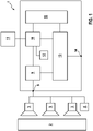
- a monitoring system 1 is shown in a schematic block diagram as an exemplary embodiment of the invention.
- the surveillance system 1 is used to monitor a surveillance area 2 and is and/or can be connected, for example, to a plurality of surveillance cameras 3 .
- the surveillance system 1 is connected to a storage device 4 which buffers or stores surveillance images from the surveillance cameras 3 and outputs them to the surveillance system 1 .
- the surveillance system 1 includes the surveillance cameras 3 and/or the storage device 4.
- the monitoring area 2 can be designed, for example, as a public square, a street or also as the interior of a building. It is possible for the surveillance area 2 to be continuous or—depending on the distribution of the surveillance cameras 3—fragmented or non-contiguous.
- the surveillance system 1 has an input interface 5, via which the surveillance images from the surveillance cameras 3 are transferred to the surveillance system 1, optionally with intermediate storage in the storage device 4.
- the data coupling can be wired, wireless and/or via the Internet.
- the monitoring system 1 is designed to provide a position-dependent protection area 6a, b, c ( figure 2 ) depending on the position of a surveillance object 7 and to carry it with the surveillance object 7 in the surveillance area 2.
- Both objects 7, 8 are in the form of moving objects, ie objects that are moving in the monitored area 2 in relation to a static or quasi-static background.
- the surveillance system 1 includes a localization module 9 for locating the surveillance object 7 and optionally the further object 8.
- the surveillance object 7 can be selected manually by the user or automatically. For example, a user can select the monitored object by selecting it, in particular by clicking on it, using an interaction device 11, for example a computer mouse, a touchpad or the like.
- the localization of the further object 8 can also be implemented in another module. As a result, the localization module 9 outputs a current position of the monitored object 7 and, optionally, a current position of the further object 8 as well.
- the localization module 9 has a detection unit and a tracking unit, the detection unit detecting or recognizing the surveillance object by means of digital image processing and the Tracking unit enables the tracking of the surveillance object across multiple surveillance images, so that for each surveillance image a current position of the surveillance object 7 or a line of movement of the surveillance object 7 across multiple surveillance images and thus over time is determined.
- the current position of the surveillance object 7 is transferred to a definition module 10 in which the surveillance object 7 is assigned the position-dependent protection area 6a, b, c.
- the protection zone 6a, b, c is initialized or redefined, the protection zone 6a is assigned to the surveillance object 7 either manually, automatically or fully automatically.
- the monitoring system 1 in particular the definition module 10, suggests various options for a protection area 6a, with one of the options being selected by the user via the interaction device 11.
- the definition takes place depending on further image processing results, such as e.g. person recognition, situation evaluation, in particular time of day, full/empty scene, etc. Any data required for the semi-automatic or fully automatic definition of the protection area are retrieved from a database 12.
- the definition module 10 is designed to shift the protection zone 6a depending on the position of the monitored object 7 in order to generate the further protection zones 6b, c in this way; so the protection area 6a in the figure 2 shifted parallel to the movement of the surveillance object 7, with the protection zones 6a, b, c spatially viewed each occupying the same relative position to the surveillance object 7.
- the protection areas 6a, b, c defined in this way are transferred to a monitoring module 13 by the definition module 10 and the position of the further object 8 by the localization module 9 or by another module.
- the monitoring module 13 is designed to check whether the further object 8 violates or contacts or leaves the protected area 6a, b, c.
- a predefined rule can be stored in the database 12 for checking, with the monitoring module 13 checking, for example, whether the further object 8 enters the protected area 6a, b, c, the further object 8 is in the protected area 6a for a predetermined minimum duration , b, c resides or whether the other object 8 is performing suspicious actions with reference to or within the protected area 6 a, b, c.
- an alarm is sent via an alarm interface 14, for example to the user or a monitoring staff.
- the monitored object 7 remains in one position and the other object 8 contacts the protected area 6a, b, c.
- the monitored object 7 and the further object 8 are only treated in two dimensions, ie no depth information is used in this configuration.
- Objects 7, 8 are detected in a known manner by extracting all moving objects from the static background, for example by subtracting the current surveillance image from a reference image.
- the objects are recognized and tracked via several surveillance images. The positions of the surveillance object 7 and the further object 8 are only shown in image coordinates of the surveillance image.
- the protection areas 6a, b, c are drawn in interactively by the user, for example, and are also only defined in the image plane, with an alarm being sent to the alarm output interface 14 is output as soon as the position of the other object 8 is located within the protected area 6a, b, c.
- the surveillance system 1 has a scene model module 15 in which a three-dimensional model of the surveillance area 2 is stored.
- the positions of the two objects 7.8 are determined in the scene model and are therefore three-dimensional.
- the protection area 6a,b,c is also defined three-dimensionally.
- a line or line it is possible for a line or line to be defined on the floor of the surveillance area, with an alarm being output at the alarm output interface 14 as soon as the other object 8 has contacted or violated the protection area 6a, b, c.
- a volume in the scene model to be defined as a protection area 6a,b,c, which is carried along with the surveillance object 7.
- the surveillance area 2 defines a world coordinate system W in which the surveillance object 7 and the further object 8 move.
- the surveillance object 7 defines an object coordinate system O that is carried along, the origin of which is defined by the position of the surveillance object 7 and the alignment of which is optionally defined or predetermined by the alignment of the surveillance object 7 .
- the protected area 6a, b, c each assumes the same position in the object coordinate system O, but is shifted in the world coordinate system W together with the surveillance object 7 or its object coordinate system O.
- an automatic adjustment of the protection area 6a, b, c for the monitored object 7 is carried out in the named exemplary embodiments in order to be able to react to changed object properties.
- the protection zone 6a,b,c changes based on the speed of the object 7 to be monitored. If the monitored object 7 drives faster, the protection area 6a, b, c is increased, since the monitored object 7 poses an increased risk or the monitored object 7 needs a longer time to come to a standstill.
Landscapes
- Engineering & Computer Science (AREA)
- Physics & Mathematics (AREA)
- General Physics & Mathematics (AREA)
- Computer Vision & Pattern Recognition (AREA)
- Multimedia (AREA)
- Theoretical Computer Science (AREA)
- Signal Processing (AREA)
- Business, Economics & Management (AREA)
- Emergency Management (AREA)
- Alarm Systems (AREA)
- Closed-Circuit Television Systems (AREA)
- Image Analysis (AREA)
Claims (9)
- Système de surveillance (1) permettant de surveiller une zone à surveiller (2), comprenantune interface d'entrée (5) permettant de reprendre des images de surveillance de la zone à surveiller (2),un module de localisation (9) permettant de localiser au moins un objet à surveiller (7) mobile dans la zone à surveiller (2), le module de localisation (9) étant réalisé pour localiser une position de l'objet à surveiller (7),un module de définition (10) permettant de définir une zone de protection (6 a, b, c) dépendante de la position dans la zone à surveiller (2),un module de surveillance (13) permettant de surveiller la zone de protection (2),le module de définition (10) étant réalisé pour définir la zone de protection (6 a, b, c) dépendante de la position en fonction de la position de l'objet à surveiller mobile (7),dans lequel le module de surveillance (13) est réalisé pour déclencher un état d'alarme si un autre objet (8) entre dans la zone de protection (6 a, b, c) ou enfreint les limites de zone de protection et reste dans la zone de protection (6 a, b, c) pendant une durée prédéfinissable,caractérisé en ce que le module de définition (10) définit la zone de protection (6 a, b, c) à l'aide de propriétés d'objet de l'objet à surveiller (7),la zone de protection (6 a, b, c) étant adaptée automatiquement au moins à l'aide d'une vitesse de l'objet à surveiller mobile (7) comme propriété d'objet.
- Système de surveillance (1) selon la revendication 1, caractérisé en ce que la zone de protection (2) accompagne l'objet à surveiller (7) le long d'une ligne de déplacement de l'objet à surveiller (7).
- Système de surveillance (1) selon la revendication 1 ou 2, caractérisé en ce que la zone de protection (2) est définie par une ligne, en option fermée, dans une scène à surveiller représentée sur les images de surveillance.
- Système de surveillance (1) selon la revendication 1 ou 2, caractérisé par un module de modèle de scène (15) qui fournit un modèle de scène de la zone à surveiller (2), la zone de protection (6 a, b, c) étant définie par une ligne, en option fermée, dans le modèle de scène.
- Système de surveillance (1) selon la revendication 1, 2 ou 4, caractérisé par un ou le module de modèle de scène (15) qui fournit un modèle de scène de la zone à surveiller (2), la zone de protection (6 a, b, c) étant définie par un volume dans le modèle de scène.
- Système de surveillance (1) selon l'une quelconque des revendications précédentes, caractérisé en ce que le module de localisation (9) présente une unité de détection et une unité de poursuite de sorte que la position de l'objet à surveiller (7) peut être déterminée par traitement d'image à l'aide des images de surveillance.
- Système de surveillance (1) selon l'une quelconque des revendications précédentes, caractérisé en ce que le module de définition (10) définit la zone de protection (6 a, b, c) par une interaction d'utilisateur.
- Système de surveillance (1) selon l'une quelconque des revendications précédentes, caractérisé en ce que le module de définition (10) définit la zone de protection (6 a, b, c) à l'aide d'une classe de l'objet à surveiller (7).
- Système de surveillance (1) selon l'une quelconque des revendications précédentes, caractérisé en ce que le module de surveillance (13) est réalisé pour déclencher un état d'alarme si un autre objet (8) effectue des actions selon un schéma prédéfinissable en cas de contact ou après contact avec la zone de protection (6 a, b, c).
Applications Claiming Priority (2)
| Application Number | Priority Date | Filing Date | Title |
|---|---|---|---|
| DE102012212613.9A DE102012212613A1 (de) | 2012-07-18 | 2012-07-18 | Überwachungssystem mit positionsabhängigem Schutzbereich, Verfahren zur Überwachung eines Überwachungsbereichs sowie Computerprogramm |
| PCT/EP2013/063355 WO2014012753A1 (fr) | 2012-07-18 | 2013-06-26 | Système de surveillance à zone de protection dépendante de la position, procédé de surveillance d'une zone à surveiller et programme informatique |
Publications (2)
| Publication Number | Publication Date |
|---|---|
| EP2875498A1 EP2875498A1 (fr) | 2015-05-27 |
| EP2875498B1 true EP2875498B1 (fr) | 2022-05-04 |
Family
ID=48745916
Family Applications (1)
| Application Number | Title | Priority Date | Filing Date |
|---|---|---|---|
| EP13733261.5A Active EP2875498B1 (fr) | 2012-07-18 | 2013-06-26 | Système de surveillance à zone de protection dépendante de la position, procédé de surveillance d'une zone à surveiller et programme informatique |
Country Status (4)
| Country | Link |
|---|---|
| US (1) | US9547905B2 (fr) |
| EP (1) | EP2875498B1 (fr) |
| DE (1) | DE102012212613A1 (fr) |
| WO (1) | WO2014012753A1 (fr) |
Families Citing this family (8)
| Publication number | Priority date | Publication date | Assignee | Title |
|---|---|---|---|---|
| US20170148487A1 (en) * | 2015-11-25 | 2017-05-25 | Dell Products L.P. | Video Manipulation for Privacy Enhancement |
| US10657830B2 (en) * | 2016-03-28 | 2020-05-19 | International Business Machines Corporation | Operation of an aerial drone inside an exclusion zone |
| EP3261071B1 (fr) * | 2016-06-22 | 2020-04-01 | Outsight | Procédé et système de detection d'intrusions d'un volume sous surveillance |
| US10306403B2 (en) * | 2016-08-03 | 2019-05-28 | Honeywell International Inc. | Location based dynamic geo-fencing system for security |
| US20190208018A1 (en) * | 2018-01-02 | 2019-07-04 | Scanalytics, Inc. | System and method for smart building control using multidimensional presence sensor arrays |
| DE102018121500A1 (de) * | 2018-09-04 | 2020-03-05 | Wabco Gmbh | Verfahren zum Vorgeben von Soll-Abständen zwischen Fahrzeugen eines Fahrzeugverbundes, Auswerteeinheit sowie Fahrzeug |
| JP7023429B1 (ja) * | 2020-12-22 | 2022-02-21 | 楽天グループ株式会社 | 監視システム、及び無人走行体 |
| EP4654166A1 (fr) * | 2024-05-23 | 2025-11-26 | ZF CV Systems Global GmbH | Procédé et dispositif de surveillance d'un environnement d'un véhicule automobile |
Citations (7)
| Publication number | Priority date | Publication date | Assignee | Title |
|---|---|---|---|---|
| WO1997004428A1 (fr) * | 1995-07-20 | 1997-02-06 | Fraunhofer-Gesellschaft zur Förderung der angewandten Forschung e.V. | Systeme de surveillance interactif |
| EP1403817A1 (fr) * | 2000-09-06 | 2004-03-31 | Hitachi, Ltd. | Detecteur de comportement anormal |
| EP1703437A2 (fr) * | 2005-03-15 | 2006-09-20 | Omron Corporation | Système, dispositif et procédé de surveillance, support d'enregistrement et programme |
| EP1713275A1 (fr) * | 2004-02-03 | 2006-10-18 | Matsushita Electric Industrial Co., Ltd. | Systeme de surveillance et terminal a camera |
| US20090189983A1 (en) * | 2008-01-25 | 2009-07-30 | Sara Carlstead Brumfield | System and method for pattern based thresholding applied to video surveillance monitoring |
| US20100194566A1 (en) * | 2007-06-14 | 2010-08-05 | Nec Corporation | Monitoring system and monitoring method |
| EP2442286A1 (fr) * | 2009-06-11 | 2012-04-18 | Fujitsu Limited | Dispositif de détection de personne suspecte, procédé de détection de personne suspecte et programme de détection de personne suspecte |
Family Cites Families (1)
| Publication number | Priority date | Publication date | Assignee | Title |
|---|---|---|---|---|
| DE102007041893A1 (de) | 2007-09-04 | 2009-03-05 | Robert Bosch Gmbh | Verfahren zur Detektion und/oder Verfolgung von bewegten Objekten in einer Überwachungsszene mit Störern, Vorrichtung sowie Computerprogramm |
-
2012
- 2012-07-18 DE DE102012212613.9A patent/DE102012212613A1/de not_active Withdrawn
-
2013
- 2013-06-26 WO PCT/EP2013/063355 patent/WO2014012753A1/fr not_active Ceased
- 2013-06-26 EP EP13733261.5A patent/EP2875498B1/fr active Active
- 2013-06-26 US US14/414,543 patent/US9547905B2/en active Active
Patent Citations (7)
| Publication number | Priority date | Publication date | Assignee | Title |
|---|---|---|---|---|
| WO1997004428A1 (fr) * | 1995-07-20 | 1997-02-06 | Fraunhofer-Gesellschaft zur Förderung der angewandten Forschung e.V. | Systeme de surveillance interactif |
| EP1403817A1 (fr) * | 2000-09-06 | 2004-03-31 | Hitachi, Ltd. | Detecteur de comportement anormal |
| EP1713275A1 (fr) * | 2004-02-03 | 2006-10-18 | Matsushita Electric Industrial Co., Ltd. | Systeme de surveillance et terminal a camera |
| EP1703437A2 (fr) * | 2005-03-15 | 2006-09-20 | Omron Corporation | Système, dispositif et procédé de surveillance, support d'enregistrement et programme |
| US20100194566A1 (en) * | 2007-06-14 | 2010-08-05 | Nec Corporation | Monitoring system and monitoring method |
| US20090189983A1 (en) * | 2008-01-25 | 2009-07-30 | Sara Carlstead Brumfield | System and method for pattern based thresholding applied to video surveillance monitoring |
| EP2442286A1 (fr) * | 2009-06-11 | 2012-04-18 | Fujitsu Limited | Dispositif de détection de personne suspecte, procédé de détection de personne suspecte et programme de détection de personne suspecte |
Also Published As
| Publication number | Publication date |
|---|---|
| US20150193936A1 (en) | 2015-07-09 |
| EP2875498A1 (fr) | 2015-05-27 |
| US9547905B2 (en) | 2017-01-17 |
| DE102012212613A1 (de) | 2014-01-23 |
| WO2014012753A1 (fr) | 2014-01-23 |
Similar Documents
| Publication | Publication Date | Title |
|---|---|---|
| EP2875498B1 (fr) | Système de surveillance à zone de protection dépendante de la position, procédé de surveillance d'une zone à surveiller et programme informatique | |
| EP2297701B1 (fr) | Analyse vidéo | |
| EP2174260A2 (fr) | Dispositif pour identifier et/ou classifier des modèles de mouvements dans une séquence d'images d'une scène de surveillance, procédé et programme informatique | |
| EP2034461B1 (fr) | Procédé de détection et/ou de suivi d'objets mobiles dans une scène de surveillance présentant des perturbateurs, dispositif et programme informatique | |
| DE112010003000T5 (de) | Sichtsystem zum Überwachen von Menschen in dynamischen Umgebungen | |
| EP3188134B1 (fr) | Procédé de contrôle d'autorisations d'accès par un système de contrôle d'accès | |
| EP2324461A1 (fr) | Système de surveillance, procédé et programme informatique pour détecter et/ou suivre un objet à surveiller | |
| EP2553660B1 (fr) | Procédé pour visualiser des zones d'activité accrue dans des scènes de surveillance | |
| DE19621612C2 (de) | Vorrichtung zur Überwachung eines Gleisabschnittes in einem Bahnhof | |
| EP3808616B1 (fr) | Protection par caméra pour installations de traitement des véhicules | |
| WO2013113521A1 (fr) | Dispositif d'évaluation pour un système de surveillance ainsi que système de surveillance équipé dudit dispositif d'évaluation | |
| DE102018118421A1 (de) | Systeme und verfahren zur erkennung alarmierender bewegungsbahnen von objekten | |
| DE102018206593A1 (de) | Mobiles Erkennen von Reisenden und Objekten auf Bahnsteigen | |
| DE102006053286A1 (de) | Verfahren zur Detektion von bewegungsauffälligen Bildbereichen, Vorrichtung sowie Computerprogramm zur Durchführung des Verfahrens | |
| WO2011124483A1 (fr) | Procédé et dispositif pour localiser des personnes dans une zone prédéfinie | |
| DE102019114451A1 (de) | Aktivitätsbereiche in Videoinhalten | |
| WO1997004428A1 (fr) | Systeme de surveillance interactif | |
| EP2254104B1 (fr) | Procédé de reconnaissance automatique d'une modification de situation | |
| DE102019127826B4 (de) | Sicherer optoelektronischer Sensor und Verfahren zum Absichern eines Überwachungsbereichs | |
| DE19600958A1 (de) | Interaktives Überwachungssystem | |
| DE102007052763A1 (de) | Verfahren zur Vorhersage einer Aktion eines bewegten Objekts | |
| DE102018222683A1 (de) | Verfahren zum Erstellen einer Umgebungsrepräsentationskarte zur Überwachung eines Fahrzeugs und/oder eines Fahrzeuganhängers unter Verwendung eines Kamerasystems | |
| WO2012141574A1 (fr) | Système de détection d'intrusion destiné à déterminer la position d'un objet | |
| EP3352111B1 (fr) | Procédé de détection d'événements critiques | |
| DE102020208068A1 (de) | Verfahren zur Erkennung eines in einem Überwachungsbereich erscheinenden Objekts, Computerprogramm, Speichermedium und Steuereinrichtung |
Legal Events
| Date | Code | Title | Description |
|---|---|---|---|
| PUAI | Public reference made under article 153(3) epc to a published international application that has entered the european phase |
Free format text: ORIGINAL CODE: 0009012 |
|
| 17P | Request for examination filed |
Effective date: 20150218 |
|
| AK | Designated contracting states |
Kind code of ref document: A1 Designated state(s): AL AT BE BG CH CY CZ DE DK EE ES FI FR GB GR HR HU IE IS IT LI LT LU LV MC MK MT NL NO PL PT RO RS SE SI SK SM TR |
|
| AX | Request for extension of the european patent |
Extension state: BA ME |
|
| DAX | Request for extension of the european patent (deleted) | ||
| STAA | Information on the status of an ep patent application or granted ep patent |
Free format text: STATUS: EXAMINATION IS IN PROGRESS |
|
| 17Q | First examination report despatched |
Effective date: 20180927 |
|
| RAP1 | Party data changed (applicant data changed or rights of an application transferred) |
Owner name: ROBERT BOSCH GMBH |
|
| GRAP | Despatch of communication of intention to grant a patent |
Free format text: ORIGINAL CODE: EPIDOSNIGR1 |
|
| STAA | Information on the status of an ep patent application or granted ep patent |
Free format text: STATUS: GRANT OF PATENT IS INTENDED |
|
| INTG | Intention to grant announced |
Effective date: 20211202 |
|
| GRAS | Grant fee paid |
Free format text: ORIGINAL CODE: EPIDOSNIGR3 |
|
| GRAA | (expected) grant |
Free format text: ORIGINAL CODE: 0009210 |
|
| STAA | Information on the status of an ep patent application or granted ep patent |
Free format text: STATUS: THE PATENT HAS BEEN GRANTED |
|
| AK | Designated contracting states |
Kind code of ref document: B1 Designated state(s): AL AT BE BG CH CY CZ DE DK EE ES FI FR GB GR HR HU IE IS IT LI LT LU LV MC MK MT NL NO PL PT RO RS SE SI SK SM TR |
|
| REG | Reference to a national code |
Ref country code: GB Ref legal event code: FG4D Free format text: NOT ENGLISH |
|
| REG | Reference to a national code |
Ref country code: CH Ref legal event code: EP |
|
| REG | Reference to a national code |
Ref country code: AT Ref legal event code: REF Ref document number: 1489938 Country of ref document: AT Kind code of ref document: T Effective date: 20220515 |
|
| REG | Reference to a national code |
Ref country code: DE Ref legal event code: R096 Ref document number: 502013016133 Country of ref document: DE |
|
| REG | Reference to a national code |
Ref country code: IE Ref legal event code: FG4D Free format text: LANGUAGE OF EP DOCUMENT: GERMAN |
|
| REG | Reference to a national code |
Ref country code: LT Ref legal event code: MG9D |
|
| REG | Reference to a national code |
Ref country code: NL Ref legal event code: MP Effective date: 20220504 |
|
| PGFP | Annual fee paid to national office [announced via postgrant information from national office to epo] |
Ref country code: FR Payment date: 20220623 Year of fee payment: 10 |
|
| PG25 | Lapsed in a contracting state [announced via postgrant information from national office to epo] |
Ref country code: SE Free format text: LAPSE BECAUSE OF FAILURE TO SUBMIT A TRANSLATION OF THE DESCRIPTION OR TO PAY THE FEE WITHIN THE PRESCRIBED TIME-LIMIT Effective date: 20220504 Ref country code: PT Free format text: LAPSE BECAUSE OF FAILURE TO SUBMIT A TRANSLATION OF THE DESCRIPTION OR TO PAY THE FEE WITHIN THE PRESCRIBED TIME-LIMIT Effective date: 20220905 Ref country code: NO Free format text: LAPSE BECAUSE OF FAILURE TO SUBMIT A TRANSLATION OF THE DESCRIPTION OR TO PAY THE FEE WITHIN THE PRESCRIBED TIME-LIMIT Effective date: 20220804 Ref country code: NL Free format text: LAPSE BECAUSE OF FAILURE TO SUBMIT A TRANSLATION OF THE DESCRIPTION OR TO PAY THE FEE WITHIN THE PRESCRIBED TIME-LIMIT Effective date: 20220504 Ref country code: LT Free format text: LAPSE BECAUSE OF FAILURE TO SUBMIT A TRANSLATION OF THE DESCRIPTION OR TO PAY THE FEE WITHIN THE PRESCRIBED TIME-LIMIT Effective date: 20220504 Ref country code: HR Free format text: LAPSE BECAUSE OF FAILURE TO SUBMIT A TRANSLATION OF THE DESCRIPTION OR TO PAY THE FEE WITHIN THE PRESCRIBED TIME-LIMIT Effective date: 20220504 Ref country code: GR Free format text: LAPSE BECAUSE OF FAILURE TO SUBMIT A TRANSLATION OF THE DESCRIPTION OR TO PAY THE FEE WITHIN THE PRESCRIBED TIME-LIMIT Effective date: 20220805 Ref country code: FI Free format text: LAPSE BECAUSE OF FAILURE TO SUBMIT A TRANSLATION OF THE DESCRIPTION OR TO PAY THE FEE WITHIN THE PRESCRIBED TIME-LIMIT Effective date: 20220504 Ref country code: ES Free format text: LAPSE BECAUSE OF FAILURE TO SUBMIT A TRANSLATION OF THE DESCRIPTION OR TO PAY THE FEE WITHIN THE PRESCRIBED TIME-LIMIT Effective date: 20220504 Ref country code: BG Free format text: LAPSE BECAUSE OF FAILURE TO SUBMIT A TRANSLATION OF THE DESCRIPTION OR TO PAY THE FEE WITHIN THE PRESCRIBED TIME-LIMIT Effective date: 20220804 |
|
| PG25 | Lapsed in a contracting state [announced via postgrant information from national office to epo] |
Ref country code: RS Free format text: LAPSE BECAUSE OF FAILURE TO SUBMIT A TRANSLATION OF THE DESCRIPTION OR TO PAY THE FEE WITHIN THE PRESCRIBED TIME-LIMIT Effective date: 20220504 Ref country code: PL Free format text: LAPSE BECAUSE OF FAILURE TO SUBMIT A TRANSLATION OF THE DESCRIPTION OR TO PAY THE FEE WITHIN THE PRESCRIBED TIME-LIMIT Effective date: 20220504 Ref country code: LV Free format text: LAPSE BECAUSE OF FAILURE TO SUBMIT A TRANSLATION OF THE DESCRIPTION OR TO PAY THE FEE WITHIN THE PRESCRIBED TIME-LIMIT Effective date: 20220504 Ref country code: IS Free format text: LAPSE BECAUSE OF FAILURE TO SUBMIT A TRANSLATION OF THE DESCRIPTION OR TO PAY THE FEE WITHIN THE PRESCRIBED TIME-LIMIT Effective date: 20220904 |
|
| PG25 | Lapsed in a contracting state [announced via postgrant information from national office to epo] |
Ref country code: SM Free format text: LAPSE BECAUSE OF FAILURE TO SUBMIT A TRANSLATION OF THE DESCRIPTION OR TO PAY THE FEE WITHIN THE PRESCRIBED TIME-LIMIT Effective date: 20220504 Ref country code: SK Free format text: LAPSE BECAUSE OF FAILURE TO SUBMIT A TRANSLATION OF THE DESCRIPTION OR TO PAY THE FEE WITHIN THE PRESCRIBED TIME-LIMIT Effective date: 20220504 Ref country code: RO Free format text: LAPSE BECAUSE OF FAILURE TO SUBMIT A TRANSLATION OF THE DESCRIPTION OR TO PAY THE FEE WITHIN THE PRESCRIBED TIME-LIMIT Effective date: 20220504 Ref country code: EE Free format text: LAPSE BECAUSE OF FAILURE TO SUBMIT A TRANSLATION OF THE DESCRIPTION OR TO PAY THE FEE WITHIN THE PRESCRIBED TIME-LIMIT Effective date: 20220504 Ref country code: DK Free format text: LAPSE BECAUSE OF FAILURE TO SUBMIT A TRANSLATION OF THE DESCRIPTION OR TO PAY THE FEE WITHIN THE PRESCRIBED TIME-LIMIT Effective date: 20220504 Ref country code: CZ Free format text: LAPSE BECAUSE OF FAILURE TO SUBMIT A TRANSLATION OF THE DESCRIPTION OR TO PAY THE FEE WITHIN THE PRESCRIBED TIME-LIMIT Effective date: 20220504 |
|
| REG | Reference to a national code |
Ref country code: CH Ref legal event code: PL |
|
| REG | Reference to a national code |
Ref country code: DE Ref legal event code: R097 Ref document number: 502013016133 Country of ref document: DE |
|
| REG | Reference to a national code |
Ref country code: BE Ref legal event code: MM Effective date: 20220630 |
|
| PG25 | Lapsed in a contracting state [announced via postgrant information from national office to epo] |
Ref country code: MC Free format text: LAPSE BECAUSE OF FAILURE TO SUBMIT A TRANSLATION OF THE DESCRIPTION OR TO PAY THE FEE WITHIN THE PRESCRIBED TIME-LIMIT Effective date: 20220504 |
|
| PLBE | No opposition filed within time limit |
Free format text: ORIGINAL CODE: 0009261 |
|
| STAA | Information on the status of an ep patent application or granted ep patent |
Free format text: STATUS: NO OPPOSITION FILED WITHIN TIME LIMIT |
|
| PG25 | Lapsed in a contracting state [announced via postgrant information from national office to epo] |
Ref country code: AL Free format text: LAPSE BECAUSE OF FAILURE TO SUBMIT A TRANSLATION OF THE DESCRIPTION OR TO PAY THE FEE WITHIN THE PRESCRIBED TIME-LIMIT Effective date: 20220504 |
|
| 26N | No opposition filed |
Effective date: 20230207 |
|
| PG25 | Lapsed in a contracting state [announced via postgrant information from national office to epo] |
Ref country code: LU Free format text: LAPSE BECAUSE OF NON-PAYMENT OF DUE FEES Effective date: 20220626 Ref country code: LI Free format text: LAPSE BECAUSE OF NON-PAYMENT OF DUE FEES Effective date: 20220630 Ref country code: IE Free format text: LAPSE BECAUSE OF NON-PAYMENT OF DUE FEES Effective date: 20220626 Ref country code: CH Free format text: LAPSE BECAUSE OF NON-PAYMENT OF DUE FEES Effective date: 20220630 |
|
| PG25 | Lapsed in a contracting state [announced via postgrant information from national office to epo] |
Ref country code: SI Free format text: LAPSE BECAUSE OF FAILURE TO SUBMIT A TRANSLATION OF THE DESCRIPTION OR TO PAY THE FEE WITHIN THE PRESCRIBED TIME-LIMIT Effective date: 20220504 Ref country code: BE Free format text: LAPSE BECAUSE OF NON-PAYMENT OF DUE FEES Effective date: 20220630 |
|
| REG | Reference to a national code |
Ref country code: AT Ref legal event code: MM01 Ref document number: 1489938 Country of ref document: AT Kind code of ref document: T Effective date: 20220626 |
|
| PG25 | Lapsed in a contracting state [announced via postgrant information from national office to epo] |
Ref country code: AT Free format text: LAPSE BECAUSE OF NON-PAYMENT OF DUE FEES Effective date: 20220626 |
|
| PG25 | Lapsed in a contracting state [announced via postgrant information from national office to epo] |
Ref country code: IT Free format text: LAPSE BECAUSE OF FAILURE TO SUBMIT A TRANSLATION OF THE DESCRIPTION OR TO PAY THE FEE WITHIN THE PRESCRIBED TIME-LIMIT Effective date: 20220504 |
|
| PG25 | Lapsed in a contracting state [announced via postgrant information from national office to epo] |
Ref country code: HU Free format text: LAPSE BECAUSE OF FAILURE TO SUBMIT A TRANSLATION OF THE DESCRIPTION OR TO PAY THE FEE WITHIN THE PRESCRIBED TIME-LIMIT; INVALID AB INITIO Effective date: 20130626 |
|
| PG25 | Lapsed in a contracting state [announced via postgrant information from national office to epo] |
Ref country code: MK Free format text: LAPSE BECAUSE OF FAILURE TO SUBMIT A TRANSLATION OF THE DESCRIPTION OR TO PAY THE FEE WITHIN THE PRESCRIBED TIME-LIMIT Effective date: 20220504 Ref country code: CY Free format text: LAPSE BECAUSE OF FAILURE TO SUBMIT A TRANSLATION OF THE DESCRIPTION OR TO PAY THE FEE WITHIN THE PRESCRIBED TIME-LIMIT Effective date: 20220504 |
|
| PG25 | Lapsed in a contracting state [announced via postgrant information from national office to epo] |
Ref country code: FR Free format text: LAPSE BECAUSE OF NON-PAYMENT OF DUE FEES Effective date: 20230630 |
|
| PG25 | Lapsed in a contracting state [announced via postgrant information from national office to epo] |
Ref country code: MT Free format text: LAPSE BECAUSE OF FAILURE TO SUBMIT A TRANSLATION OF THE DESCRIPTION OR TO PAY THE FEE WITHIN THE PRESCRIBED TIME-LIMIT Effective date: 20220504 |
|
| PG25 | Lapsed in a contracting state [announced via postgrant information from national office to epo] |
Ref country code: BG Free format text: LAPSE BECAUSE OF FAILURE TO SUBMIT A TRANSLATION OF THE DESCRIPTION OR TO PAY THE FEE WITHIN THE PRESCRIBED TIME-LIMIT Effective date: 20220504 |
|
| PG25 | Lapsed in a contracting state [announced via postgrant information from national office to epo] |
Ref country code: BG Free format text: LAPSE BECAUSE OF FAILURE TO SUBMIT A TRANSLATION OF THE DESCRIPTION OR TO PAY THE FEE WITHIN THE PRESCRIBED TIME-LIMIT Effective date: 20220504 |
|
| PGFP | Annual fee paid to national office [announced via postgrant information from national office to epo] |
Ref country code: GB Payment date: 20250620 Year of fee payment: 13 |
|
| PGFP | Annual fee paid to national office [announced via postgrant information from national office to epo] |
Ref country code: DE Payment date: 20250627 Year of fee payment: 13 |
|
| PG25 | Lapsed in a contracting state [announced via postgrant information from national office to epo] |
Ref country code: TR Free format text: LAPSE BECAUSE OF FAILURE TO SUBMIT A TRANSLATION OF THE DESCRIPTION OR TO PAY THE FEE WITHIN THE PRESCRIBED TIME-LIMIT Effective date: 20220504 |