EP2876061A2 - Führung für ein Transportband in einer Druckmaschine - Google Patents
Führung für ein Transportband in einer Druckmaschine Download PDFInfo
- Publication number
- EP2876061A2 EP2876061A2 EP14193003.2A EP14193003A EP2876061A2 EP 2876061 A2 EP2876061 A2 EP 2876061A2 EP 14193003 A EP14193003 A EP 14193003A EP 2876061 A2 EP2876061 A2 EP 2876061A2
- Authority
- EP
- European Patent Office
- Prior art keywords
- guide
- conveyor belt
- load
- load bridges
- bridges
- Prior art date
- Legal status (The legal status is an assumption and is not a legal conclusion. Google has not performed a legal analysis and makes no representation as to the accuracy of the status listed.)
- Granted
Links
- 238000007639 printing Methods 0.000 title claims abstract description 38
- 238000000034 method Methods 0.000 claims abstract description 11
- 239000000758 substrate Substances 0.000 claims abstract description 8
- 239000000463 material Substances 0.000 description 4
- 238000006073 displacement reaction Methods 0.000 description 3
- 239000000725 suspension Substances 0.000 description 3
- 239000000853 adhesive Substances 0.000 description 1
- 230000001070 adhesive effect Effects 0.000 description 1
- 230000002411 adverse Effects 0.000 description 1
- 238000013459 approach Methods 0.000 description 1
- 239000003086 colorant Substances 0.000 description 1
- 238000002788 crimping Methods 0.000 description 1
- 239000004744 fabric Substances 0.000 description 1
- 238000007646 gravure printing Methods 0.000 description 1
- 238000004519 manufacturing process Methods 0.000 description 1
- 238000007645 offset printing Methods 0.000 description 1
- 229920002635 polyurethane Polymers 0.000 description 1
- 239000004814 polyurethane Substances 0.000 description 1
- 238000007650 screen-printing Methods 0.000 description 1
- 239000004753 textile Substances 0.000 description 1
- 238000003466 welding Methods 0.000 description 1
Images



Classifications
-
- B—PERFORMING OPERATIONS; TRANSPORTING
- B65—CONVEYING; PACKING; STORING; HANDLING THIN OR FILAMENTARY MATERIAL
- B65G—TRANSPORT OR STORAGE DEVICES, e.g. CONVEYORS FOR LOADING OR TIPPING, SHOP CONVEYOR SYSTEMS OR PNEUMATIC TUBE CONVEYORS
- B65G15/00—Conveyors having endless load-conveying surfaces, i.e. belts and like continuous members, to which tractive effort is transmitted by means other than endless driving elements of similar configuration
- B65G15/60—Arrangements for supporting or guiding belts, e.g. by fluid jets
- B65G15/64—Arrangements for supporting or guiding belts, e.g. by fluid jets for automatically maintaining the position of the belts
-
- B—PERFORMING OPERATIONS; TRANSPORTING
- B65—CONVEYING; PACKING; STORING; HANDLING THIN OR FILAMENTARY MATERIAL
- B65G—TRANSPORT OR STORAGE DEVICES, e.g. CONVEYORS FOR LOADING OR TIPPING, SHOP CONVEYOR SYSTEMS OR PNEUMATIC TUBE CONVEYORS
- B65G39/00—Rollers, e.g. drive rollers, or arrangements thereof incorporated in roller-ways or other types of mechanical conveyors
- B65G39/10—Arrangements of rollers
- B65G39/12—Arrangements of rollers mounted on framework
- B65G39/16—Arrangements of rollers mounted on framework for aligning belts or chains
Definitions
- the invention relates to a guide element for an endless conveyor belt for guiding substrates during the printing process of a printing machine with a number of guide rollers, which are brought into contact with the conveyor belt and a number of first load bridges for receiving a sub number of guide rollers. Furthermore, the invention relates to a guide system for an endless conveyor belt for guiding substrates during the printing process of a printing press with a number of guide elements, each comprising at least one guide roller, which is brought into contact with the conveyor belt.
- Such conveyor belts are usually formed as endless belts and are used to flat webs, especially those of a critical material, eg. As those with high tendency to default safely through a machine, such as a printing press to lead.
- Such bands are used for example in the WO 82/00975 or the DE 10023689 disclosed. They usually consist of a multilayer structure in which a textile fabric layer absorbs the tension forces and in which a cover layer is formed so that it can be coated with an adhesive that establishes the bond between the tape and the substrate.
- Today's endless belts are usually made of a polyurethane, which is particularly well suited for these purposes. It is also fusible, which allows welding the two ends of the belt in the machine into an endless belt. For this purpose, both ends are usually provided with a serrated conclusion, which are welded together under the influence of high temperature and high pressure.
- the AT 209250 discloses, for example, a spring coil, which is fastened in the conveyor belt and runs in corresponding guide rails.
- a spring coil which is fastened in the conveyor belt and runs in corresponding guide rails.
- the EP 402725 be used instead of the coil springs rollers that run in externally mounted guide rails.
- the idea of placing rolls on one side of the strip edge has already been used in the twisted wire tapes US 1,821,664 demonstrated.
- a guide rail is proposed here, to which the band edge can be supported.
- various forms of grooves in the band which run in corresponding rails. All these solutions have in common that either the required guidance accuracy is not achieved or that the life of the belt is greatly limited due to increased friction and increased wear.
- position controllers have also been developed, which mostly work via the angular adjustment of at least one guide roller.
- Such belt control systems are eg in the DD 237643 or in the WO 98/22373 disclosed. These control systems have in common that they work very sluggish, that their realization is very complex and that they only act on the inlet of the pressure line. The further the strip moves away from the controlled roll, the lower the influence of the control action. Therefore, with this method, the required accuracy in longer endless belts, for example, for use in longer print runs, also not be achieved.
- the invention is therefore based on the object, guide elements and a guide system for an endless conveyor belt for guiding substrates during the printing process in a printing machine indicate that the shortage the lateral zig-zag course or the drifting off of the conveyor belt in the simplest possible way fixes.
- this object is achieved according to the invention by a number of second load bridges are provided, in each of which a number of the first load bridges and / or a number of further second load bridges are pivotally mounted.
- the invention is based on the consideration that a particularly quiet and the zigzag course adapted guidance of the conveyor belt can then take place when the guide rollers optimally, i. can be applied to the conveyor belt with uniform contact forces.
- This can be achieved if the guide rollers or the first load bridges are at least partially pivotally mounted and thus can be employed at the correct angle to the conveyor belt. Therefore, second load bridges are provided in which these first load bridges or further second load bridges are pivotally mounted.
- the load bridges in a preferred embodiment are pivotable about an axis perpendicular to the conveyor belt plane, so that the guide rollers can optimally invest in the edge of the conveyor belt.
- At least one guide roller, a first load bridge and / or a second load bridge in an advantageous embodiment are mounted resiliently transversely to the conveyor belt running direction.
- a particularly gentle guidance of the conveyor belt is achieved, which additionally suppresses a zigzag course.
- the spring strength of the suspension to the needs, for example, depending on the material of the conveyor belt, the speed of the conveyor belt or other system parameters, set in a particularly advantageous embodiment targeted and also changed.
- an optimal conveyor belt guide can be achieved.
- each first load bridge a even number of guide rollers.
- the use of two guide rollers in a first load bridge has been found to be particularly preferred.
- the number of first load bridges is straight and every second load bridge can accommodate two first or second load bridges.
- a pyramid-like structure of the load bridges is made possible, which can absorb the zigzag course of the conveyor belt particularly well and optionally cushion it. This results in a particularly preferred number of second load bridges of n-1, where n is even and the number of first load bridges.
- the guide roller comprises a circumferential groove in which the transport path is guided.
- a circumferential groove in which the transport path is guided.
- other profiles of the guide roller are possible, so in particular a convex cross-sectional shape of the guide roller is advantageous.
- the guide elements are arranged with at least one guide roller on both sides of the conveyor belt.
- the guide system has at least one pair of guide elements according to the invention, which are arranged substantially opposite one another.
- a further preferred embodiment consists of a single first load bridge, in which one or more guide rollers are provided and which is mounted without the use of a second load bridge directly pivotable about an axis perpendicular to the conveyor belt plane or pivotally and resiliently.
- the individual load bridges or guide rollers it is particularly advantageous if at least one of the paired guide elements is mounted resiliently transversely to the transport direction. It has proved to be particularly advantageous if the rigidly mounted guide elements are arranged on one side of the conveyor belt and the spring-mounted guide elements on the other side of the belt. But it is also possible to arrange resilient and rigid guide elements alternately or irregularly alternately.
- the advantages achieved by the invention are, in particular, that in the successive printing with multiple pressure points, a higher ink register accuracy can be achieved without the life of the conveyor belt is adversely affected. Also, the high cost of an active control can be deliberately avoided.
- the invention also makes it possible to combine printing processes with a printing blanket solution in which higher process forces arise. Conveyor belts in printing machines are well known with screen printing and digital printing machines, where only a small impact on the endless belt. With the guide according to the invention, for example, the offset printing method, gravure printing or flexographic printing can now also be used on a conveyor belt.
- the guide element 1 comprises by way of example four guide rollers 2, which can be brought into contact with the conveyor belt 4. In each case two of these guide rollers 2 are arranged in a first load bridge 6. Depending on the embodiment of the guide element, these guide rollers 2 can be mounted resiliently transversely to the running direction x of the conveyor belt 4, so that they can absorb and compensate for a zigzag course, ie a displacement of the conveyor belt 4 transversely to the running direction x.
- the two first load bridges 4 of the guide element 1 are in turn mounted in a second load bridge 8 about an axis 10 perpendicular to the conveyor belt plane 12 pivotally.
- the second load bridge 8 is mounted about an axis 10 perpendicular to the conveyor belt plane 12 pivotally mounted on a carrier 14 of the printing press or another stationary element of the printing press.
- FIG. 2 An alternative attachment possibility of the guide element 1 after Fig. 1 on the supports 14 of the printing press is in the Fig. 2 shown.
- the second one Load bridge 8 is pivotally mounted about an axis 10 perpendicular to the conveyor belt plane 12 on a lever member 16 which fixes the guide member 1 to a carrier 14 of the printing machine or other stationary element of the printing press.
- This lever member 16 is in turn arranged about an axis 10 perpendicular to the conveyor belt plane 12 pivotally mounted on the carrier 14.
- the second load bridge is mounted transversely to the running direction x of the conveyor belt by means of a spring element 26 resiliently on the or another carrier 14, so that the entire guide element 1 compensate for the lateral movement of the conveyor belt 4 and counteract this by the spring force.
- FIG. 3 an embodiment of a spring element 1 with eight guide rollers 2 is shown.
- two guide rollers 2 are arranged in a first load bridge 6 and two first load bridges about an axis 10 perpendicular to the conveyor belt plane 12 pivotally in a second load bridge 8.
- these two second load bridges 8 are arranged in a third second load bridge 8 about an axis 10 perpendicular to the conveyor belt plane 12 pivotally, whereby a pyramid structure of the load bridges 6, 8 is formed.
- This third second load bridge 8 can then be directly attached to a support 14 of the printing press or - as in the Fig.
- a guide element 1 is shown with only two guide rollers 2, which are arranged on a single first load bridge 6.
- This first load bridge 6 is in contrast to the above Embodiments not pivotally mounted on a second load bridge, but arranged directly on a support 14 pivotally about an axis 10 perpendicular to the conveyor belt plane 12.
- the first load bridge 6 is resiliently mounted on a carrier 14, so that the forces due to a lateral displacement of the conveyor belt 4 can be collected very well.
- a number of such guide elements 1 is used in particular in a guide system.
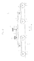
- Such a guide system 18 is in one embodiment in Fig. 5 exemplified.
- This guide system comprises a number of guide elements 1.
- These guide elements can from the Fig. 1 - 4th but may also consist essentially only of a single guide roller 2, which are applied to the conveyor belt 4.
- the guide elements 1 of the guide system according to Fig. 5 are thus not limited to the above embodiments.
- the guide elements 1 after Fig. 5 are specifically arranged opposite each other to allow both sides a safe and accurate web guide.
- a pair of guide elements is arranged directly in front of the printing unit 20 in order to prevent a displacement of the conveyor belt 4 transversely to the running direction x immediately before the printing unit 20 and thus also during the printing process.
- a particularly high quality of the printed product can be achieved.
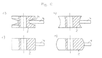
- Fig. 6 Various preferred profiles of the guide rollers 2 are in Fig. 6 shown in cross section.
- a circumferential groove (24) Fig. 6 a
- a concave surface Fig. 6b
- the conveyor belt can be partially enclosed or encompassed by the surface of the guide rollers so that the conveyor belt 4 lies securely in the guide roller 2 and can not jump out.
- a planar Fig. 6 c
- even a convex surface Fig. 6 d
Landscapes
- Engineering & Computer Science (AREA)
- Mechanical Engineering (AREA)
- Feeding Of Articles By Means Other Than Belts Or Rollers (AREA)
- Structure Of Belt Conveyors (AREA)
- Delivering By Means Of Belts And Rollers (AREA)
Abstract
Description
- Die Erfindung bezieht sich auf ein Führungselement für ein endloses Transportband zum Führen von Substraten während des Druckvorgangs einer Druckmaschine mit einer Anzahl von Führungsrollen, die mit dem Transportband in Kontakt bringbar sind und einer Anzahl von ersten Lastbrücken zur Aufnahme jeweils einer Unteranzahl der Führungsrollen. Des Weiteren bezieht sich die Erfindung auf ein Führungssystem für ein endloses Transportband zum Führen von Substraten während des Druckvorgangs einer Druckmaschine mit einer Anzahl von Führungselementen, die jeweils mindestens eine Führungsrolle umfassen, die mit dem Transportband in Kontakt bringbar ist.
- Derartige Transportbänder sind üblicherweise als Endlosbänder ausgebildet und werden eingesetzt, um flächige Warenbahnen, insbesondere solche aus einem kritischen Material, z. B. solche mit hoher Neigung zu Verzug, sicher durch eine Maschine, beispielsweise eine Druckmaschine, zu führen. Solche Bänder werden beispielsweise in der
WO 82/00975 DE 10023689 offenbart. Sie bestehen meistens aus einem mehrlagigen Aufbau, bei dem eine textile Gewebelage die Spannkräfte aufnimmt und bei dem eine Deckschicht so ausgebildet ist, dass diese mit einem Adhäsiv beschichtet werden kann, das die Verbindung zwischen Band und Substrat herstellt. Heutige Endlosbänder bestehen meist aus einem Polyurethan, das sich für diese Zwecke besonders gut eignet. Es ist zudem schmelzbar, was das Verschweißen der beiden Enden des Bandes in der Maschine zu einem endlosen Band ermöglicht. Dazu werden beide Enden meist mit einem zackenförmigen Abschluss versehen, die unter dem Einfluss hoher Temperatur und hohen Drucks miteinander verschweißt werden. - Es ist bekannt, dass solche Bänder aufgrund von Fertigungstoleranzen, Schwankungen der Materialparameter sowie der Unstetigkeit im Bereich der Schweißnaht zu einem Zick-Zack-Lauf oder einem Abdriften tendieren. Bei einem Einsatz des Endlosbandes in einer Druckmaschine für den Transport eines Bedruckstoffes ergeben sich dabei beim Nacheinanderdruck mit mehreren Farben seitliche Registerversätze, die die Qualität des Druckproduktes erheblich einschränken. Um dieses Problem zu umgehen, sind verschiedene Lösungsansätze entwickelt worden.
- Die
AT 209250 EP 402725 US 1,821, 664 aufgezeigt. Alternativ wird hier eine Führungsschiene vorgeschlagen, an die sich die Bandkante abstützen kann. Ferner wurden in derDE 4034427 verschiedene Formen an Nuten im Band vorgeschlagen, die in entsprechenden Profilschienen laufen. Allen diesen Lösungen ist gemein, dass entweder die erforderliche Führungsgenauigkeit nicht erreicht wird oder dass die Lebensdauer des Bandes aufgrund erhöhter Reibung und erhöhtem Verschleiß stark begrenzt wird. - Um diese Nachteile zu beheben, wurden auch Positionsregler entwickelt, die meistens über die Winkelverstellung mindestens einer Führungswalze arbeiten. Solche Bandregelsysteme werden z.B. in der
DD 237643 WO 98/22373 - Der Erfindung liegt daher die Aufgabe zugrunde, Führungselemente und ein Führungssystem für ein endloses Transportband zum Führen von Substraten während des Druckvorgangs in einer Druckmaschine anzugeben, die den Mangel des seitlichen Zick-Zack-Verlaufs oder des Abdriftens des Transportbandes auf möglichst einfache Art und Weise behebt.
- Bezüglich der Führungselemente wird diese Aufgabe erfindungsgemäß gelöst, indem eine Anzahl von zweiten Lastbrücken vorgesehen sind, in denen jeweils eine Anzahl der ersten Lastbrücken und/oder eine Anzahl weiterer zweiter Lastbrücken schwenkbar gelagert sind.
- Die Erfindung geht dabei von der Überlegung aus, dass eine besonders ruhige und dem Zick-Zack-Verlauf angepasste Führung des Transportbandes dann erfolgen kann, wenn die Führungsrollen optimal, d.h. mit gleichmäßigen Anstellkräften an das Transportband angelegt werden können. Dies kann dann erreicht werden, wenn die Führungsrollen bzw. die ersten Lastbrücken zumindest teilweise schwenkbar gelagert sind und somit im richtigen Winkel an das Transportband angestellt werden können. Daher sind zweite Lastbrücken vorgesehen, in denen diese ersten Lastbrücken oder weitere zweite Lastbrücken schwenkbar gelagert sind. Dabei sind die Lastbrücken in bevorzugter Ausführung um eine Achse senkrecht zur Transportbandebene schwenkbar, damit sich die Führungsrollen optimal an den Rand des Transportbandes anlegen können.
- Um ein Einzwängen des endlosen Transportbandes und die damit verbundene Reduktion der Lebensdauer zu vermeiden, sind mindestens eine Führungsrolle, eine erste Lastbrücke und/oder eine zweite Lastbrücke in vorteilhafter Ausführung quer zur Transportbandlaufrichtung federnd gelagert. Dadurch wird eine besonders sanfte Führung des Transportbandes erreicht, die einen Zick-Zack-Verlauf zusätzlich unterdrückt. Dabei kann die Federstärke der Federung an die Bedürfnisse, beispielsweise in Abhängigkeit des Material des Transportbandes, der Geschwindigkeit des Transportbandes oder weiterer Systemparameter, in besonders vorteilhafter Ausführung gezielt eingestellt und auch verändert werden. Somit kann eine optimale Transportbandführung erreicht werden.
- Für eine möglichst symmetrische und somit auch gleichmäßige Führung der Transportbahn umfasst in bevorzugter Ausführung jede erste Lastbrücke eine gerade Anzahl von Führungsrollen. Dabei hat sich die Verwendung von zwei Führungsrollen in einer ersten Lastbrücke als besonders bevorzugt herausgestellt. Wie auch bei der Anzahl von Führungsrollen in den ersten Lastbrücken ist es besonders vorteilhaft, wenn die Anzahl der ersten Lastbrücken gerade ist und jede zweite Lastbrücke zwei erste oder zweite Lastbrücken aufnehmen kann. Dadurch wird eine pyramidenähnliche Struktur der Lastbrücken ermöglicht, die den Zick-Zack-Verlauf des Transportbandes besonders gut aufnehmen und gegebenenfalls abfedern können. Dadurch ergibt sich eine besonders bevorzugte Anzahl von zweiten Lastbrücken von n-1, wobei n gerade und die Anzahl der ersten Lastbrücken ist.
- Damit die Führungsrollen die Transportbahn auch bei hohen Geschwindigkeiten sicher führen können, umfasst in vorteilhafter Ausführung die Führungsrolle eine Umfangsnut, in der die Transportbahn geführt wird. Neben der Umfangsnut sind aber auch andere Profile der Führungsrolle möglich, so ist insbesondere auch eine konvexe Querschnittsform der Führungsrolle vorteilhaft.
- Bezüglich des Führungssystems wird die obige Aufgabe erfindungsgemäß gelöst, indem die Führungselemente mit mindestens je einer Führungsrolle auf beiden Seiten des Transportbandes angeordnet sind. Zur Vermeidung des Zick-Zack-Verlaufes ist es dabei besonders vorteilhaft, wenn das Führungssystem zumindest ein Paar der erfindungsgemäßen Führungselemente aufweist, die im Wesentlichen gegenüberliegend voneinander angeordnet sind. Durch Einwirkung der Führungsrollen auf beiden Seiten des Transportbandes wird dieses im Bereich der Führungsrollen besonders einfach quer zur Bahnlaufrichtung ausgerichtet und in der gewünschten Position gehalten.
- Eine weitere bevorzugte Ausführung besteht aus einer einzelnen ersten Lastbrücke, in der eine oder mehrere Führungsrollen vorgesehen sind und die ohne die Verwendung einer zweiten Lastbrücke direkt schwenkbar um eine Achse senkrecht zur Transportbandebene oder schwenkbar und federnd gelagert ist. Wie auch bei den einzelnen Lastbrücken oder Führungsrollen ist es von besonderem Vorteil, wenn mindestens eines der paarweise angeordneten Führungselemente quer zur Transportrichtung federnd gelagert ist. Dabei hat sich als besonders vorteilhaft erwiesen, wenn die starr gelagerten Führungselemente auf einer Seite des Transportbandes und die federnd gelagerten Führungselemente auf der anderen Seite des Bandes angeordnet sind. Es ist aber ebenso möglich, federnde und starre Führungselemente alternierend oder unregelmäßig abwechselnd anzuordnen.
- Besonders gute Ergebnisse können erzielt werden, wenn zumindest ein Teil der Führungselemente im Leertrum des Transportbandes angeordnet sind und/oder vor jeder Druckeinheit. Es hat sich für den Bandlauf besonders vorteilhaft herausgestellt, wenn ein Paar von Führungselementen im Leertrum vor der vorderen Umlenkwalze angeordnet wird. Dadurch kann erreicht werden, dass das Band bereits sehr ruhig in den Lastbereich einläuft. Bei einer Anordnung von Führungselemente vor jeder Druckeinheit kann erreicht werden, dass das Transportband zumindest im Druckbereich optimal ausgerichtet ist und somit die Substrate ohne Versatz gedruckt werden können. Dies ermöglicht eine besonders hohe Druckqualität.
- Die mit der Erfindung erzielten Vorteile liegen insbesondere darin, dass beim Nacheinanderdruck mit mehreren Druckstellen eine höhere Farbregistergenauigkeit erreicht werden kann, ohne dass die Lebensdauer des Transportbandes negativ beeinflusst wird. Auch kann dadurch der hohe Aufwand einer aktiven Regelung bewusst umgangen werden. Durch die Erfindung ist es zudem möglich, Druckverfahren mit einer Druckdeckenlösung zu kombinieren, bei denen höhere Verfahrenskräfte entstehen. Transportbänder in Druckmaschinen sind hinlänglich mit Siebdruck- und Digitaldruckmaschinen bekannt, bei denen nur eine geringe Einwirkung auf das Endlosband erfolgt. Mit der erfindungsgemäßen Führung können nun beispielsweise auch das Offsetdruckverfahren, der Tiefdruck oder der Flexodruck auf einem Transportband angewandt werden.
- Ein Ausführungsbeispiel der Erfindung wird anhand einer Zeichnung näher erläutert. Darin zeigen:
-
Fig. 1 ein Führungselement mit zwei ersten Lastbrücken, -
Fig. 2 ein federnd gelagertes Führungselement, -
Fig. 3 ein federnd gelagertes Führungselement mit vier ersten Lastbrücken, -
Fig. 4 ein Führungselement mit einer ersten Lastbrücke, -
Fig. 5 ein endloses Transportband mit einem Führungssystem, -
Fig. 6 verschiedene Querschnittsprofile einzelner Führungsrollen. - Gleiche Teile sind in allen Figuren mit denselben Bezugszeichen versehen.
- Ein Ausführungsbeispiel eines Führungselements 1 ist in der
Fig. 1 dargestellt. Das Führungselement 1 umfasst dabei beispielhaft vier Führungsrollen 2, die mit dem Transportband 4 in Kontakt bringbar sind. Jeweils zwei dieser Führungsrollen 2 sind in einer ersten Lastbrücke 6 angeordnet. Je nach Ausführungsform des Führungselements können diese Führungsrollen 2 quer zur Laufrichtung x des Transportbandes 4 federnd gelagert sein, sodass sie einen Zick-Zack-Verlauf, also eine Verschiebung des Transportbandes 4 quer zur Laufrichtung x abfedern und ausgleichen können. - Die beiden ersten Lastbrücken 4 des Führungselements 1 sind wiederum in einer zweiten Lastbrücke 8 um eine Achse 10 senkrecht zur Transportbandebene 12 schwenkbar gelagert. Somit können die ersten Lastbrücken 6 durch eine Schwenkbewegung relativ zur zweiten Lastbrücke 8 Unebenheiten des Randes des Transportbandes 4 aber auch die Zick-Zack-Bewegungen des Transportbandes 4 besonders gut ausgleichen. Die zweite Lastbrücke 8 ist dabei um eine Achse 10 senkrecht zur Transportbandebene 12 schwenkbar an einem Träger 14 der Druckmaschine oder einem anderen ortsfesten Element der Druckmaschine befestigt.
- Eine alternative Befestigungsmöglichkeit des Führungselementes 1 nach
Fig. 1 an den Trägern 14 der Druckmaschine ist in derFig. 2 dargestellt. Hier ist die zweite Lastbrücke 8 um eine Achse 10 senkrecht zur Transportbandebene 12 schwenkbar an einem Hebelelement 16 befestigt, der das Führungselement 1 an einem Träger 14 der Druckmaschine oder einem anderen ortsfesten Element der Druckmaschine befestigt. Dieses Hebelelement 16 ist dabei wiederum um eine Achse 10 senkrecht zur Transportbandebene 12 schwenkbar an dem Träger 14 angeordnet. Zusätzlich ist allerdings die zweite Lastbrücke quer zur Laufrichtung x des Transportbandes mittels eines Federelements 26 federnd an dem oder einem weiteren Träger 14 gelagert, sodass auch das ganze Führungselement 1 die seitliche Bewegung des Transportbandes 4 ausgleichen und über die Federkraft dieser entgegenwirken kann. - In
Fig. 3 ist ein Ausführungsbeispiel eines Federelements 1 mit acht Führungsrollen 2 dargestellt. Dabei sind wieder jeweils zwei Führungsrollen 2 in einer ersten Lastbrücke 6 angeordnet und jeweils zwei erste Lastbrücken um eine Achse 10 senkrecht zur Transportbandebene 12 schwenkbar in einer zweiten Lastbrücke 8. Im Unterschied zum Ausführungsbeispiel nachFig. 1 oderFig. 2 sind nun diese beiden zweiten Lastbrücken 8 in einer dritten zweiten Lastbrücke 8 um eine Achse 10 senkrecht zur Transportbandebene 12 schwenkbar angeordnet, wodurch eine Pyramidenstruktur der Lastbrücken 6, 8 entsteht. Auch diese dritte zweite Lastbrücke 8 kann dann wieder direkt an einem Träger 14 der Druckmaschine befestigt werden oder aber - wie in derFig. 3 - dargestellt, wieder über ein Hebelelement 16 und einem Federelement 26 federnd gelagert sein. Neben der möglichen federnd gelagerten Aufhängung an einem Träger 14 der Druckmaschine, sind im Ausführungsbeispiel aber auch die ersten Lastbrücken 6 über Federelemente 26 federnd an den zweiten Lastbrücken gelagert. Es ergibt sich von selbst, dass je nach Anwendung alle oder auch nur ein Teil der Lastbrücken 6, 8 federnd gelagert sein können. Hierdurch kann eine an die individuellen Gegebenheiten angepasste Federung des Führungselements erzielt werden. - Im Ausführungsbeispiel nach
Fig. 4 ist ein Führungselement 1 mit nur zwei Führungsrollen 2 dargestellt, die an einer einzelnen ersten Lastbrücke 6 angeordnet sind. Diese erste Lastbrücke 6 ist im Gegensatz zu den obigen Ausführungsbeispielen nicht an einer zweiten Lastbrücke schwenkbar gelagert, sondern direkt an einem Träger 14 schwenkbar um eine Achse 10 senkrecht zur Transportbandebene 12 angeordnet. Wie auch im Ausführungsbeispiel nach derFig. 2 , ist die erste Lastbrücke 6 federnd an einem Träger 14 gelagert, sodass die Kräfte aufgrund einer seitlichen Verschiebung des Transportbandes 4 besonders gut aufgefangen werden können. Eine Anzahl derartiger Führungselemente 1 wird insbesondere in einem Führungssystem verwendet. - Ein solches Führungssystem 18 ist in einem Ausführungsbeispiel in
Fig. 5 beispielhaft dargestellt. Dieses Führungssystem umfasst eine Anzahl von Führungselementen 1. Diese Führungselemente können dabei den aus denFig. 1 - 4 entsprechen, können aber auch im Wesentlichen nur aus einer einzelnen Führungsrolle 2 bestehen, die an das Transportband 4 angelegt werden. Die Führungselemente 1 des Führungssystems nachFig. 5 sind somit nicht auf die obigen Ausführungsbeispiele beschränkt. Die Führungselemente 1 nachFig. 5 sind dabei gezielt gegenüber voneinander angeordnet, um beidseitig eine sichere und genaue Bahnführung zu ermöglichen. Dabei ist ein Führungselementepaar direkt vor der Druckeinheit 20 angeordnet, um eine Verschiebung des Transportbandes 4 quer zur Laufrichtung x unmittelbar vor der Druckeinheit 20 und somit auch während des Druckvorganges zu verhindern. Somit kann eine besonders hohe Qualität des Druckproduktes erreicht werden. Zusätzlich ist ein Führungselementepaar im Leertrum des Transportbandes 4, direkt vor der vorderen Umlenkwalze 22 angeordnet. Dies gewährleistet einen ruhigen Einlauf des Transportbandes in den Lastbereich. - Verschiedene bevorzugte Profile der Führungsrollen 2 sind in
Fig. 6 im Querschnitt dargestellt. Bei der Verwendung einer Umfangsnut (24) (Fig. 6 a) oder einer konkaven Ausbildung der Oberfläche (Fig. 6 b) kann das Transportband von der Oberfläche der Führungsrollen teilweise umschlossen bzw. umgriffen werden, sodass das Transportband 4 sicher in der Führungsrolle 2 liegt und nicht herausspringen kann. Aber auch eine planare (Fig. 6 c ) oder gar eine konvexe Oberfläche (Fig. 6 d ) ist möglich, da diese den Randbereich des Transportbandes weniger stark beanspruchen. -
- 1
- Führungselement
- 2
- Führungsrolle
- 4
- Transportband
- 6
- erste Lastbrücke
- 8
- zweite Lastbrücke
- 10
- Schwenkachse
- 12
- Transportbandebene
- 14
- Träger
- 16
- Hebelelement
- 18
- Führungssystem
- 20
- Druckeinheit
- 22
- Umlenkwalze
- 24
- Umfangsnut
- 26
- Federelement
- x
- Laufrichtung des Transportbandes
Claims (20)
- Führungselement (1) für ein endloses Transportband (4) zum Führen von Substraten während des Druckvorgangs einer Druckmaschine mit einer Anzahl von Führungsrollen (2), die mit dem Transportband (4) in Kontakt bringbar sind und einer Anzahl von ersten Lastbrücken (6) zur Aufnahme jeweils einer Unteranzahl der Führungsrollen (2),
dadurch gekennzeichnet, dass
eine Anzahl von zweiten Lastbrücken (8) vorgesehen sind, in denen jeweils eine Anzahl der ersten Lastbrücken (6) und/oder eine Anzahl weiterer zweiter Lastbrücken (8) schwenkbar gelagert sind. - Führungselement (1) nach Anspruch 1, dadurch gekennzeichnet, dass die ersten Lastbrücken (6) oder die weiteren zweiten Lastbrücken (8) um eine Achse senkrecht zur Transportbandebene (12) schwenkbar sind.
- Führungselement (1) nach Anspruch 1 oder 2, dadurch gekennzeichnet, dass alle oder eine Unteranzahl der Führungsrollen (2) quer zur Transportbandlaufrichtung (x) federnd in den ersten Lastbrücken (6) gelagert sind.
- Führungselement (1) nach einem der Ansprüche 1 bis 3, dadurch gekennzeichnet, dass alle oder eine Unteranzahl der ersten Lastbrücken (6) quer zur Transportbandlaufrichtung (x) federnd in den zweiten Lastbrücken (6) gelagert sind.
- Führungselement (1) nach einem der Ansprüche 1 bis 4, dadurch gekennzeichnet, dass, sofern zweite Lastbrücken (8) in weiteren zweiten Lastbrücken (8) gelagert sind, alle oder eine Unteranzahl von diesen in den zweiten Lastbrücken (8) gelagerten zweiten Lastbrücken (8) quer zur Transportbandlaufrichtung (x) federnd gelagert sind.
- Führungselement (1) nach einem der Ansprüche 1 bis 5, dadurch gekennzeichnet, dass die Federstärke der federnd gelagerten Führungsrollen (2) oder Lastbrücken (6, 8) veränderbar ausgeführt ist.
- Führungselement (1) nach einem der Ansprüche 1 bis 6, dadurch gekennzeichnet, dass jede erste Lastbrücke (6) eine gerade Anzahl von Führungsrollen (2) umfasst.
- Führungselement (1) nach einem der Ansprüche 1 bis 7, dadurch gekennzeichnet, dass die Anzahl der ersten Lastbrücken (6) gerade ist.
- Führungselement (1) nach Anspruch 8, dadurch gekennzeichnet, dass die Anzahl der zweiten Lastbrücken (8) n-1 ist, wobei n die Anzahl der ersten Lastbrücken (6) ist.
- Führungselement (1) nach einem der Ansprüche 1 bis 9, dadurch gekennzeichnet, dass die Führungsrollen (2) zur Führung der Transportbahn (4) eine Umfangsnut (24) umfassen.
- Führungssystem (18) für ein endloses Transportband zum Führen von Substraten während des Druckvorgangs einer Druckmaschine mit einer Anzahl von Führungselementen (1), die jeweils mindestens eine Führungsrolle (2) umfassen, die mit dem Transportband (4) in Kontakt bringbar ist, dadurch gekennzeichnet, dass die Führungselemente (1) auf beiden Seiten des Transportbandes (4) angeordnet sind.
- Führungssystem (18) nach Anspruch 11, dadurch gekennzeichnet, dass die Führungselemente (1) eine Anzahl von ersten Lastbrücken (6) zur Aufnahme jeweils einer Anzahl von Führungsrollen (2) umfassen, wobei die ersten Lastbrücken (6) schwenkbar um eine Achse senkrecht zur Transportbandebene (12) ausgeführt sind.
- Führungssystem (18) nach Anspruch 11, dadurch gekennzeichnet, dass zumindest ein Führungselement (1) nach einem der Ansprüche 1 bis 10 ausgebildet ist.
- Führungssystem (18) einem der Ansprüche 11 bis 13, dadurch gekennzeichnet, dass mindestens zwei Führungselemente (1) im Wesentlichen gegenüberliegend voneinander angeordnet sind.
- Führungssystem (18) nach einem der Ansprüche 11 bis 14, dadurch gekennzeichnet, dass eine Anzahl der Führungselemente (1) quer zur Transportbandlaufrichtung (12) federnd gelagert sind.
- Führungssystem (18) nach Anspruch 15, dadurch gekennzeichnet, dass die starr gelagerten Führungselemente (1) und die federnd gelagerten Führungselemente (1) zumindest auf einer Seite des Transportbandes (4) alternierend oder unregelmäßig abwechselnd angeordnet sind.
- Führungssystem (18) nach Anspruch 15, dadurch gekennzeichnet, dass die Führungselemente (1) auf der ersten Seite des Transportbandes (4) starr gelagert und auf der zweiten Seite des Bandes federnd gelagert sind.
- Führungssystem (18) nach einem der Ansprüche 15 bis 17, dadurch gekennzeichnet, dass die Federstärke der federnd gelagerten Führungselemente (1) veränderbar ausgeführt ist.
- Führungssystem (18) nach einem der Ansprüche 11 bis 18, dadurch gekennzeichnet, dass zumindest ein Teil der Führungselemente (1) im Leertrum vor der Umlenkwalze (22) angeordnet ist.
- Führungssystem (18) nach einem der Ansprüche 11 bis 18, dadurch gekennzeichnet, dass zumindest ein Teil der Führungselemente (1) vor jeder Druckeinheit (20) angeordnet ist.
Applications Claiming Priority (1)
| Application Number | Priority Date | Filing Date | Title |
|---|---|---|---|
| DE102013112827.0A DE102013112827A1 (de) | 2013-11-20 | 2013-11-20 | Führung für ein Transportband in einer Druckmaschine |
Publications (3)
| Publication Number | Publication Date |
|---|---|
| EP2876061A2 true EP2876061A2 (de) | 2015-05-27 |
| EP2876061A3 EP2876061A3 (de) | 2015-09-02 |
| EP2876061B1 EP2876061B1 (de) | 2017-08-02 |
Family
ID=51904747
Family Applications (1)
| Application Number | Title | Priority Date | Filing Date |
|---|---|---|---|
| EP14193003.2A Not-in-force EP2876061B1 (de) | 2013-11-20 | 2014-11-13 | Führung für ein Transportband in einer Druckmaschine |
Country Status (3)
| Country | Link |
|---|---|
| EP (1) | EP2876061B1 (de) |
| CN (1) | CN104647882A (de) |
| DE (1) | DE102013112827A1 (de) |
Cited By (1)
| Publication number | Priority date | Publication date | Assignee | Title |
|---|---|---|---|---|
| WO2017098407A1 (en) * | 2015-12-11 | 2017-06-15 | Uniset S.R.L. | Kit for monitoring conveyor belts and the like, and related method |
Families Citing this family (1)
| Publication number | Priority date | Publication date | Assignee | Title |
|---|---|---|---|---|
| DE102016104768A1 (de) * | 2016-03-15 | 2017-09-21 | Meurer Verpackungssysteme Gmbh | Fördereinrichtung |
Citations (8)
| Publication number | Priority date | Publication date | Assignee | Title |
|---|---|---|---|---|
| US1821664A (en) | 1925-08-29 | 1931-09-01 | Hartford Empire Co | Conveyer guide |
| AT209250B (de) | 1957-12-19 | 1960-05-25 | Zimmer S Erben Kg | Vorrichtung zur Führung von Förderbändern |
| WO1982000975A1 (en) | 1980-09-12 | 1982-04-01 | Dahlgren H | Planetary conveyor system |
| DD237643A5 (de) | 1984-10-27 | 1986-07-23 | �����@������������������k�� | Steuervorrichtung zum ausrichten eines um zwei rollen umlaufenden endlosbandes |
| EP0402725A1 (de) | 1989-06-14 | 1990-12-19 | Bridgestone/Firestone, Inc. | Förderband und Führungssystem dafür |
| DE4034427A1 (de) | 1989-11-06 | 1991-05-08 | Andritz Ag Maschf | Foerderbandgurt, verfahren und vorrichtung zu seiner herstellung sowie seitenfuehrung fuer einen solchen gurt |
| WO1998022373A1 (de) | 1996-11-19 | 1998-05-28 | Santrade Ltd. | Einrichtung zur steuerung des geradlaufes eines endlosen bandes |
| DE10023689A1 (de) | 2000-05-16 | 2001-12-06 | Roland Man Druckmasch | Kombinierte Druckmaschine |
Family Cites Families (2)
| Publication number | Priority date | Publication date | Assignee | Title |
|---|---|---|---|---|
| DE2723033C2 (de) * | 1977-05-21 | 1979-07-12 | Conrad Scholtz Ag, 2000 Hamburg | Kurvengurtförderer |
| US6494451B2 (en) * | 2001-03-19 | 2002-12-17 | Hewlett-Packard Company | Anti-skew idler roller system |
-
2013
- 2013-11-20 DE DE102013112827.0A patent/DE102013112827A1/de not_active Withdrawn
-
2014
- 2014-11-13 EP EP14193003.2A patent/EP2876061B1/de not_active Not-in-force
- 2014-11-20 CN CN201410666183.0A patent/CN104647882A/zh active Pending
Patent Citations (8)
| Publication number | Priority date | Publication date | Assignee | Title |
|---|---|---|---|---|
| US1821664A (en) | 1925-08-29 | 1931-09-01 | Hartford Empire Co | Conveyer guide |
| AT209250B (de) | 1957-12-19 | 1960-05-25 | Zimmer S Erben Kg | Vorrichtung zur Führung von Förderbändern |
| WO1982000975A1 (en) | 1980-09-12 | 1982-04-01 | Dahlgren H | Planetary conveyor system |
| DD237643A5 (de) | 1984-10-27 | 1986-07-23 | �����@������������������k�� | Steuervorrichtung zum ausrichten eines um zwei rollen umlaufenden endlosbandes |
| EP0402725A1 (de) | 1989-06-14 | 1990-12-19 | Bridgestone/Firestone, Inc. | Förderband und Führungssystem dafür |
| DE4034427A1 (de) | 1989-11-06 | 1991-05-08 | Andritz Ag Maschf | Foerderbandgurt, verfahren und vorrichtung zu seiner herstellung sowie seitenfuehrung fuer einen solchen gurt |
| WO1998022373A1 (de) | 1996-11-19 | 1998-05-28 | Santrade Ltd. | Einrichtung zur steuerung des geradlaufes eines endlosen bandes |
| DE10023689A1 (de) | 2000-05-16 | 2001-12-06 | Roland Man Druckmasch | Kombinierte Druckmaschine |
Cited By (1)
| Publication number | Priority date | Publication date | Assignee | Title |
|---|---|---|---|---|
| WO2017098407A1 (en) * | 2015-12-11 | 2017-06-15 | Uniset S.R.L. | Kit for monitoring conveyor belts and the like, and related method |
Also Published As
| Publication number | Publication date |
|---|---|
| EP2876061A3 (de) | 2015-09-02 |
| DE102013112827A1 (de) | 2015-05-21 |
| CN104647882A (zh) | 2015-05-27 |
| EP2876061B1 (de) | 2017-08-02 |
Similar Documents
| Publication | Publication Date | Title |
|---|---|---|
| DE3628282A1 (de) | Stationaere stuetzvorrichtung | |
| WO2009030409A2 (de) | Verfahren zum herstellen einer solarzelle | |
| DE4413501A1 (de) | Verfahren und Vorrichtung zur Faserbündelimprägnierung | |
| EP2876061B1 (de) | Führung für ein Transportband in einer Druckmaschine | |
| DE3045939A1 (de) | Traegerstreifen zur maschinellen anbringung an behaeltern | |
| DE4407405C2 (de) | Trockenpartie | |
| EP1074381A1 (de) | Prägestation | |
| DE19711271C2 (de) | Längenmeßsystem | |
| AT402746B (de) | Doppelsiebformer mit örtlich verstellbarer entwässerungsleiste | |
| EP0521966B1 (de) | Druckmittel-stützeinrichtung | |
| DE10335758C5 (de) | Verfahren und Druckwerk zur Beeinflussung der lateralen Bahnspreizung insbesondere an Rotationsdruckmaschinen | |
| DE202008000890U1 (de) | Bahnspreizeinrichtung für eine Rotationsdruckmaschine und damit ausgerüstete Rotationsdruckmaschine | |
| DE102005048246B4 (de) | Rotationsdruckmaschine mit Längendehnungs-Kompensator und Verfahren zum Bedrucken einer längsgeschnittenen Bahn | |
| WO2017198572A1 (de) | Vorrichtung zum spreizen eines faserbündels, insbesondere eines carbon-faserbündels | |
| AT399355B (de) | Vorrichtung zur entwässerung von faserstoff-flüssigkeit-mischungen | |
| DE2758721A1 (de) | Reibungsverstaerkende endenausfuehrung fuer blattfedern | |
| DE102007015694A1 (de) | Spinnmaschine | |
| DE9414450U1 (de) | Deckelkarde mit mindestens einem System umlaufend angetriebener Deckelstäbe | |
| EP1395509A1 (de) | Verfahren und vorrichtung zum umlenken von bändern | |
| DE2635006B2 (de) | Vorrichtung zur automatischen Abstandsregelung zwischen einem Druckkopf und einem zu bedruckenden Informationsträger | |
| DE2725356C2 (de) | Vorrichtung zum Festhalten und Bewegen von textilen Bahnen | |
| EP0436150A1 (de) | Verfahren und Anordnung zur Einstellung einer definierten Spannung in breitgeführten laufenden Warenbahnen | |
| DE102005005302A1 (de) | Druckwerk einer Druckmaschine | |
| DE2951643A1 (de) | Schussfadenmagazin fuer kettenwirkmaschinen | |
| DE8708849U1 (de) | Doppeltragwalzen-Wickelmaschine |
Legal Events
| Date | Code | Title | Description |
|---|---|---|---|
| PUAI | Public reference made under article 153(3) epc to a published international application that has entered the european phase |
Free format text: ORIGINAL CODE: 0009012 |
|
| 17P | Request for examination filed |
Effective date: 20141113 |
|
| AK | Designated contracting states |
Kind code of ref document: A2 Designated state(s): AL AT BE BG CH CY CZ DE DK EE ES FI FR GB GR HR HU IE IS IT LI LT LU LV MC MK MT NL NO PL PT RO RS SE SI SK SM TR |
|
| AX | Request for extension of the european patent |
Extension state: BA ME |
|
| PUAL | Search report despatched |
Free format text: ORIGINAL CODE: 0009013 |
|
| AK | Designated contracting states |
Kind code of ref document: A3 Designated state(s): AL AT BE BG CH CY CZ DE DK EE ES FI FR GB GR HR HU IE IS IT LI LT LU LV MC MK MT NL NO PL PT RO RS SE SI SK SM TR |
|
| AX | Request for extension of the european patent |
Extension state: BA ME |
|
| RIC1 | Information provided on ipc code assigned before grant |
Ipc: B65G 39/16 20060101ALI20150724BHEP Ipc: B65G 15/64 20060101AFI20150724BHEP |
|
| R17P | Request for examination filed (corrected) |
Effective date: 20160302 |
|
| RBV | Designated contracting states (corrected) |
Designated state(s): AL AT BE BG CH CY CZ DE DK EE ES FI FR GB GR HR HU IE IS IT LI LT LU LV MC MK MT NL NO PL PT RO RS SE SI SK SM TR |
|
| 17Q | First examination report despatched |
Effective date: 20160705 |
|
| GRAP | Despatch of communication of intention to grant a patent |
Free format text: ORIGINAL CODE: EPIDOSNIGR1 |
|
| INTG | Intention to grant announced |
Effective date: 20170412 |
|
| GRAS | Grant fee paid |
Free format text: ORIGINAL CODE: EPIDOSNIGR3 |
|
| GRAA | (expected) grant |
Free format text: ORIGINAL CODE: 0009210 |
|
| AK | Designated contracting states |
Kind code of ref document: B1 Designated state(s): AL AT BE BG CH CY CZ DE DK EE ES FI FR GB GR HR HU IE IS IT LI LT LU LV MC MK MT NL NO PL PT RO RS SE SI SK SM TR |
|
| REG | Reference to a national code |
Ref country code: CH Ref legal event code: EP Ref country code: AT Ref legal event code: REF Ref document number: 914196 Country of ref document: AT Kind code of ref document: T Effective date: 20170815 |
|
| REG | Reference to a national code |
Ref country code: IE Ref legal event code: FG4D Free format text: LANGUAGE OF EP DOCUMENT: GERMAN |
|
| REG | Reference to a national code |
Ref country code: DE Ref legal event code: R096 Ref document number: 502014004787 Country of ref document: DE |
|
| REG | Reference to a national code |
Ref country code: NL Ref legal event code: MP Effective date: 20170802 |
|
| REG | Reference to a national code |
Ref country code: LT Ref legal event code: MG4D |
|
| PG25 | Lapsed in a contracting state [announced via postgrant information from national office to epo] |
Ref country code: SE Free format text: LAPSE BECAUSE OF FAILURE TO SUBMIT A TRANSLATION OF THE DESCRIPTION OR TO PAY THE FEE WITHIN THE PRESCRIBED TIME-LIMIT Effective date: 20170802 Ref country code: FI Free format text: LAPSE BECAUSE OF FAILURE TO SUBMIT A TRANSLATION OF THE DESCRIPTION OR TO PAY THE FEE WITHIN THE PRESCRIBED TIME-LIMIT Effective date: 20170802 Ref country code: HR Free format text: LAPSE BECAUSE OF FAILURE TO SUBMIT A TRANSLATION OF THE DESCRIPTION OR TO PAY THE FEE WITHIN THE PRESCRIBED TIME-LIMIT Effective date: 20170802 Ref country code: LT Free format text: LAPSE BECAUSE OF FAILURE TO SUBMIT A TRANSLATION OF THE DESCRIPTION OR TO PAY THE FEE WITHIN THE PRESCRIBED TIME-LIMIT Effective date: 20170802 Ref country code: NO Free format text: LAPSE BECAUSE OF FAILURE TO SUBMIT A TRANSLATION OF THE DESCRIPTION OR TO PAY THE FEE WITHIN THE PRESCRIBED TIME-LIMIT Effective date: 20171102 Ref country code: NL Free format text: LAPSE BECAUSE OF FAILURE TO SUBMIT A TRANSLATION OF THE DESCRIPTION OR TO PAY THE FEE WITHIN THE PRESCRIBED TIME-LIMIT Effective date: 20170802 |
|
| PG25 | Lapsed in a contracting state [announced via postgrant information from national office to epo] |
Ref country code: IS Free format text: LAPSE BECAUSE OF FAILURE TO SUBMIT A TRANSLATION OF THE DESCRIPTION OR TO PAY THE FEE WITHIN THE PRESCRIBED TIME-LIMIT Effective date: 20171202 Ref country code: PL Free format text: LAPSE BECAUSE OF FAILURE TO SUBMIT A TRANSLATION OF THE DESCRIPTION OR TO PAY THE FEE WITHIN THE PRESCRIBED TIME-LIMIT Effective date: 20170802 Ref country code: BG Free format text: LAPSE BECAUSE OF FAILURE TO SUBMIT A TRANSLATION OF THE DESCRIPTION OR TO PAY THE FEE WITHIN THE PRESCRIBED TIME-LIMIT Effective date: 20171102 Ref country code: RS Free format text: LAPSE BECAUSE OF FAILURE TO SUBMIT A TRANSLATION OF THE DESCRIPTION OR TO PAY THE FEE WITHIN THE PRESCRIBED TIME-LIMIT Effective date: 20170802 Ref country code: ES Free format text: LAPSE BECAUSE OF FAILURE TO SUBMIT A TRANSLATION OF THE DESCRIPTION OR TO PAY THE FEE WITHIN THE PRESCRIBED TIME-LIMIT Effective date: 20170802 Ref country code: GR Free format text: LAPSE BECAUSE OF FAILURE TO SUBMIT A TRANSLATION OF THE DESCRIPTION OR TO PAY THE FEE WITHIN THE PRESCRIBED TIME-LIMIT Effective date: 20171103 Ref country code: LV Free format text: LAPSE BECAUSE OF FAILURE TO SUBMIT A TRANSLATION OF THE DESCRIPTION OR TO PAY THE FEE WITHIN THE PRESCRIBED TIME-LIMIT Effective date: 20170802 |
|
| PG25 | Lapsed in a contracting state [announced via postgrant information from national office to epo] |
Ref country code: RO Free format text: LAPSE BECAUSE OF FAILURE TO SUBMIT A TRANSLATION OF THE DESCRIPTION OR TO PAY THE FEE WITHIN THE PRESCRIBED TIME-LIMIT Effective date: 20170802 Ref country code: DK Free format text: LAPSE BECAUSE OF FAILURE TO SUBMIT A TRANSLATION OF THE DESCRIPTION OR TO PAY THE FEE WITHIN THE PRESCRIBED TIME-LIMIT Effective date: 20170802 Ref country code: CZ Free format text: LAPSE BECAUSE OF FAILURE TO SUBMIT A TRANSLATION OF THE DESCRIPTION OR TO PAY THE FEE WITHIN THE PRESCRIBED TIME-LIMIT Effective date: 20170802 |
|
| REG | Reference to a national code |
Ref country code: DE Ref legal event code: R097 Ref document number: 502014004787 Country of ref document: DE |
|
| PG25 | Lapsed in a contracting state [announced via postgrant information from national office to epo] |
Ref country code: IT Free format text: LAPSE BECAUSE OF FAILURE TO SUBMIT A TRANSLATION OF THE DESCRIPTION OR TO PAY THE FEE WITHIN THE PRESCRIBED TIME-LIMIT Effective date: 20170802 Ref country code: SK Free format text: LAPSE BECAUSE OF FAILURE TO SUBMIT A TRANSLATION OF THE DESCRIPTION OR TO PAY THE FEE WITHIN THE PRESCRIBED TIME-LIMIT Effective date: 20170802 Ref country code: SM Free format text: LAPSE BECAUSE OF FAILURE TO SUBMIT A TRANSLATION OF THE DESCRIPTION OR TO PAY THE FEE WITHIN THE PRESCRIBED TIME-LIMIT Effective date: 20170802 Ref country code: EE Free format text: LAPSE BECAUSE OF FAILURE TO SUBMIT A TRANSLATION OF THE DESCRIPTION OR TO PAY THE FEE WITHIN THE PRESCRIBED TIME-LIMIT Effective date: 20170802 |
|
| PLBE | No opposition filed within time limit |
Free format text: ORIGINAL CODE: 0009261 |
|
| STAA | Information on the status of an ep patent application or granted ep patent |
Free format text: STATUS: NO OPPOSITION FILED WITHIN TIME LIMIT |
|
| PG25 | Lapsed in a contracting state [announced via postgrant information from national office to epo] |
Ref country code: MC Free format text: LAPSE BECAUSE OF FAILURE TO SUBMIT A TRANSLATION OF THE DESCRIPTION OR TO PAY THE FEE WITHIN THE PRESCRIBED TIME-LIMIT Effective date: 20170802 |
|
| 26N | No opposition filed |
Effective date: 20180503 |
|
| PG25 | Lapsed in a contracting state [announced via postgrant information from national office to epo] |
Ref country code: CH Free format text: LAPSE BECAUSE OF NON-PAYMENT OF DUE FEES Effective date: 20171130 Ref country code: LI Free format text: LAPSE BECAUSE OF NON-PAYMENT OF DUE FEES Effective date: 20171130 |
|
| PG25 | Lapsed in a contracting state [announced via postgrant information from national office to epo] |
Ref country code: SI Free format text: LAPSE BECAUSE OF FAILURE TO SUBMIT A TRANSLATION OF THE DESCRIPTION OR TO PAY THE FEE WITHIN THE PRESCRIBED TIME-LIMIT Effective date: 20170802 Ref country code: LU Free format text: LAPSE BECAUSE OF NON-PAYMENT OF DUE FEES Effective date: 20171113 |
|
| REG | Reference to a national code |
Ref country code: FR Ref legal event code: ST Effective date: 20180731 Ref country code: BE Ref legal event code: MM Effective date: 20171130 |
|
| REG | Reference to a national code |
Ref country code: IE Ref legal event code: MM4A |
|
| PG25 | Lapsed in a contracting state [announced via postgrant information from national office to epo] |
Ref country code: MT Free format text: LAPSE BECAUSE OF FAILURE TO SUBMIT A TRANSLATION OF THE DESCRIPTION OR TO PAY THE FEE WITHIN THE PRESCRIBED TIME-LIMIT Effective date: 20170802 |
|
| PG25 | Lapsed in a contracting state [announced via postgrant information from national office to epo] |
Ref country code: FR Free format text: LAPSE BECAUSE OF NON-PAYMENT OF DUE FEES Effective date: 20171130 Ref country code: IE Free format text: LAPSE BECAUSE OF NON-PAYMENT OF DUE FEES Effective date: 20171113 |
|
| REG | Reference to a national code |
Ref country code: DE Ref legal event code: R081 Ref document number: 502014004787 Country of ref document: DE Owner name: MANROLAND GOSS WEB SYSTEMS GMBH, DE Free format text: FORMER OWNER: MANROLAND WEB SYSTEMS GMBH, 86153 AUGSBURG, DE |
|
| PG25 | Lapsed in a contracting state [announced via postgrant information from national office to epo] |
Ref country code: BE Free format text: LAPSE BECAUSE OF NON-PAYMENT OF DUE FEES Effective date: 20171130 |
|
| PGFP | Annual fee paid to national office [announced via postgrant information from national office to epo] |
Ref country code: DE Payment date: 20181120 Year of fee payment: 5 |
|
| PG25 | Lapsed in a contracting state [announced via postgrant information from national office to epo] |
Ref country code: HU Free format text: LAPSE BECAUSE OF FAILURE TO SUBMIT A TRANSLATION OF THE DESCRIPTION OR TO PAY THE FEE WITHIN THE PRESCRIBED TIME-LIMIT; INVALID AB INITIO Effective date: 20141113 |
|
| GBPC | Gb: european patent ceased through non-payment of renewal fee |
Effective date: 20181113 |
|
| PG25 | Lapsed in a contracting state [announced via postgrant information from national office to epo] |
Ref country code: CY Free format text: LAPSE BECAUSE OF FAILURE TO SUBMIT A TRANSLATION OF THE DESCRIPTION OR TO PAY THE FEE WITHIN THE PRESCRIBED TIME-LIMIT Effective date: 20170802 |
|
| PG25 | Lapsed in a contracting state [announced via postgrant information from national office to epo] |
Ref country code: MK Free format text: LAPSE BECAUSE OF FAILURE TO SUBMIT A TRANSLATION OF THE DESCRIPTION OR TO PAY THE FEE WITHIN THE PRESCRIBED TIME-LIMIT Effective date: 20170802 |
|
| PG25 | Lapsed in a contracting state [announced via postgrant information from national office to epo] |
Ref country code: GB Free format text: LAPSE BECAUSE OF NON-PAYMENT OF DUE FEES Effective date: 20181113 |
|
| PG25 | Lapsed in a contracting state [announced via postgrant information from national office to epo] |
Ref country code: TR Free format text: LAPSE BECAUSE OF FAILURE TO SUBMIT A TRANSLATION OF THE DESCRIPTION OR TO PAY THE FEE WITHIN THE PRESCRIBED TIME-LIMIT Effective date: 20170802 |
|
| PG25 | Lapsed in a contracting state [announced via postgrant information from national office to epo] |
Ref country code: PT Free format text: LAPSE BECAUSE OF FAILURE TO SUBMIT A TRANSLATION OF THE DESCRIPTION OR TO PAY THE FEE WITHIN THE PRESCRIBED TIME-LIMIT Effective date: 20170802 |
|
| REG | Reference to a national code |
Ref country code: DE Ref legal event code: R119 Ref document number: 502014004787 Country of ref document: DE |
|
| PG25 | Lapsed in a contracting state [announced via postgrant information from national office to epo] |
Ref country code: AL Free format text: LAPSE BECAUSE OF FAILURE TO SUBMIT A TRANSLATION OF THE DESCRIPTION OR TO PAY THE FEE WITHIN THE PRESCRIBED TIME-LIMIT Effective date: 20170802 |
|
| PG25 | Lapsed in a contracting state [announced via postgrant information from national office to epo] |
Ref country code: DE Free format text: LAPSE BECAUSE OF NON-PAYMENT OF DUE FEES Effective date: 20200603 |
|
| REG | Reference to a national code |
Ref country code: AT Ref legal event code: MM01 Ref document number: 914196 Country of ref document: AT Kind code of ref document: T Effective date: 20191113 |
|
| PG25 | Lapsed in a contracting state [announced via postgrant information from national office to epo] |
Ref country code: AT Free format text: LAPSE BECAUSE OF NON-PAYMENT OF DUE FEES Effective date: 20191113 |