EP2876069B1 - Kuvertiersystem und Verfahren zur Ausrichtung von Bögen - Google Patents
Kuvertiersystem und Verfahren zur Ausrichtung von Bögen Download PDFInfo
- Publication number
- EP2876069B1 EP2876069B1 EP14192784.8A EP14192784A EP2876069B1 EP 2876069 B1 EP2876069 B1 EP 2876069B1 EP 14192784 A EP14192784 A EP 14192784A EP 2876069 B1 EP2876069 B1 EP 2876069B1
- Authority
- EP
- European Patent Office
- Prior art keywords
- sheet
- sheets
- transport
- hold module
- servo
- Prior art date
- Legal status (The legal status is an assumption and is not a legal conclusion. Google has not performed a legal analysis and makes no representation as to the accuracy of the status listed.)
- Active
Links
Images





Classifications
-
- B—PERFORMING OPERATIONS; TRANSPORTING
- B65—CONVEYING; PACKING; STORING; HANDLING THIN OR FILAMENTARY MATERIAL
- B65H—HANDLING THIN OR FILAMENTARY MATERIAL, e.g. SHEETS, WEBS, CABLES
- B65H29/00—Delivering or advancing articles from machines; Advancing articles to or into piles
- B65H29/12—Delivering or advancing articles from machines; Advancing articles to or into piles by means of the nip between two, or between two sets of, moving tapes or bands or rollers
-
- B—PERFORMING OPERATIONS; TRANSPORTING
- B65—CONVEYING; PACKING; STORING; HANDLING THIN OR FILAMENTARY MATERIAL
- B65H—HANDLING THIN OR FILAMENTARY MATERIAL, e.g. SHEETS, WEBS, CABLES
- B65H29/00—Delivering or advancing articles from machines; Advancing articles to or into piles
- B65H29/12—Delivering or advancing articles from machines; Advancing articles to or into piles by means of the nip between two, or between two sets of, moving tapes or bands or rollers
- B65H29/125—Delivering or advancing articles from machines; Advancing articles to or into piles by means of the nip between two, or between two sets of, moving tapes or bands or rollers between two sets of rollers
-
- B—PERFORMING OPERATIONS; TRANSPORTING
- B65—CONVEYING; PACKING; STORING; HANDLING THIN OR FILAMENTARY MATERIAL
- B65H—HANDLING THIN OR FILAMENTARY MATERIAL, e.g. SHEETS, WEBS, CABLES
- B65H29/00—Delivering or advancing articles from machines; Advancing articles to or into piles
- B65H29/52—Stationary guides or smoothers
-
- B—PERFORMING OPERATIONS; TRANSPORTING
- B65—CONVEYING; PACKING; STORING; HANDLING THIN OR FILAMENTARY MATERIAL
- B65H—HANDLING THIN OR FILAMENTARY MATERIAL, e.g. SHEETS, WEBS, CABLES
- B65H39/00—Associating, collating, or gathering articles or webs
- B65H39/02—Associating,collating or gathering articles from several sources
- B65H39/06—Associating,collating or gathering articles from several sources from delivery streams
-
- B—PERFORMING OPERATIONS; TRANSPORTING
- B65—CONVEYING; PACKING; STORING; HANDLING THIN OR FILAMENTARY MATERIAL
- B65H—HANDLING THIN OR FILAMENTARY MATERIAL, e.g. SHEETS, WEBS, CABLES
- B65H43/00—Use of control, checking, or safety devices, e.g. automatic devices comprising an element for sensing a variable
- B65H43/02—Use of control, checking, or safety devices, e.g. automatic devices comprising an element for sensing a variable detecting, or responding to, absence of articles
-
- B—PERFORMING OPERATIONS; TRANSPORTING
- B65—CONVEYING; PACKING; STORING; HANDLING THIN OR FILAMENTARY MATERIAL
- B65H—HANDLING THIN OR FILAMENTARY MATERIAL, e.g. SHEETS, WEBS, CABLES
- B65H2301/00—Handling processes for sheets or webs
- B65H2301/30—Orientation, displacement, position of the handled material
- B65H2301/31—Features of transport path
- B65H2301/312—Features of transport path for transport path involving at least two planes of transport forming an angle between each other
- B65H2301/3121—L-shaped
-
- B—PERFORMING OPERATIONS; TRANSPORTING
- B65—CONVEYING; PACKING; STORING; HANDLING THIN OR FILAMENTARY MATERIAL
- B65H—HANDLING THIN OR FILAMENTARY MATERIAL, e.g. SHEETS, WEBS, CABLES
- B65H2301/00—Handling processes for sheets or webs
- B65H2301/30—Orientation, displacement, position of the handled material
- B65H2301/34—Modifying, selecting, changing direction of displacement
- B65H2301/342—Modifying, selecting, changing direction of displacement with change of plane of displacement
- B65H2301/3423—Modifying, selecting, changing direction of displacement with change of plane of displacement by travelling an angled curved path section for overturning and changing feeding direction
-
- B—PERFORMING OPERATIONS; TRANSPORTING
- B65—CONVEYING; PACKING; STORING; HANDLING THIN OR FILAMENTARY MATERIAL
- B65H—HANDLING THIN OR FILAMENTARY MATERIAL, e.g. SHEETS, WEBS, CABLES
- B65H2301/00—Handling processes for sheets or webs
- B65H2301/30—Orientation, displacement, position of the handled material
- B65H2301/35—Spacing
- B65H2301/351—Spacing parallel to the direction of displacement
-
- B—PERFORMING OPERATIONS; TRANSPORTING
- B65—CONVEYING; PACKING; STORING; HANDLING THIN OR FILAMENTARY MATERIAL
- B65H—HANDLING THIN OR FILAMENTARY MATERIAL, e.g. SHEETS, WEBS, CABLES
- B65H2301/00—Handling processes for sheets or webs
- B65H2301/40—Type of handling process
- B65H2301/44—Moving, forwarding, guiding material
- B65H2301/445—Moving, forwarding, guiding material stream of articles separated from each other
- B65H2301/4451—Moving, forwarding, guiding material stream of articles separated from each other forming a stream or streams of separated articles
- B65H2301/44512—Moving, forwarding, guiding material stream of articles separated from each other forming a stream or streams of separated articles forming parallel streams of separated articles
-
- B—PERFORMING OPERATIONS; TRANSPORTING
- B65—CONVEYING; PACKING; STORING; HANDLING THIN OR FILAMENTARY MATERIAL
- B65H—HANDLING THIN OR FILAMENTARY MATERIAL, e.g. SHEETS, WEBS, CABLES
- B65H2301/00—Handling processes for sheets or webs
- B65H2301/40—Type of handling process
- B65H2301/44—Moving, forwarding, guiding material
- B65H2301/445—Moving, forwarding, guiding material stream of articles separated from each other
- B65H2301/4452—Regulating space between separated articles
-
- B—PERFORMING OPERATIONS; TRANSPORTING
- B65—CONVEYING; PACKING; STORING; HANDLING THIN OR FILAMENTARY MATERIAL
- B65H—HANDLING THIN OR FILAMENTARY MATERIAL, e.g. SHEETS, WEBS, CABLES
- B65H2301/00—Handling processes for sheets or webs
- B65H2301/40—Type of handling process
- B65H2301/44—Moving, forwarding, guiding material
- B65H2301/445—Moving, forwarding, guiding material stream of articles separated from each other
- B65H2301/4454—Merging two or more streams
-
- B—PERFORMING OPERATIONS; TRANSPORTING
- B65—CONVEYING; PACKING; STORING; HANDLING THIN OR FILAMENTARY MATERIAL
- B65H—HANDLING THIN OR FILAMENTARY MATERIAL, e.g. SHEETS, WEBS, CABLES
- B65H2511/00—Dimensions; Position; Numbers; Identification; Occurrences
- B65H2511/20—Location in space
-
- B—PERFORMING OPERATIONS; TRANSPORTING
- B65—CONVEYING; PACKING; STORING; HANDLING THIN OR FILAMENTARY MATERIAL
- B65H—HANDLING THIN OR FILAMENTARY MATERIAL, e.g. SHEETS, WEBS, CABLES
- B65H2511/00—Dimensions; Position; Numbers; Identification; Occurrences
- B65H2511/50—Occurence
- B65H2511/51—Presence
-
- B—PERFORMING OPERATIONS; TRANSPORTING
- B65—CONVEYING; PACKING; STORING; HANDLING THIN OR FILAMENTARY MATERIAL
- B65H—HANDLING THIN OR FILAMENTARY MATERIAL, e.g. SHEETS, WEBS, CABLES
- B65H2511/00—Dimensions; Position; Numbers; Identification; Occurrences
- B65H2511/50—Occurence
- B65H2511/52—Defective operating conditions
- B65H2511/528—Jam
-
- B—PERFORMING OPERATIONS; TRANSPORTING
- B65—CONVEYING; PACKING; STORING; HANDLING THIN OR FILAMENTARY MATERIAL
- B65H—HANDLING THIN OR FILAMENTARY MATERIAL, e.g. SHEETS, WEBS, CABLES
- B65H2701/00—Handled material; Storage means
- B65H2701/10—Handled articles or webs
- B65H2701/18—Form of handled article or web
- B65H2701/182—Piled package
- B65H2701/1826—Arrangement of sheets
- B65H2701/18262—Ordered set of articles forming one batch
- B65H2701/18263—Ordered set of articles forming one batch wherein each article is offset from its neighbour in the pile
-
- B—PERFORMING OPERATIONS; TRANSPORTING
- B65—CONVEYING; PACKING; STORING; HANDLING THIN OR FILAMENTARY MATERIAL
- B65H—HANDLING THIN OR FILAMENTARY MATERIAL, e.g. SHEETS, WEBS, CABLES
- B65H2801/00—Application field
- B65H2801/66—Envelope filling machines
Definitions
- the present subject matter relates to techniques and equipment to control the alignment of sheets of paper that are assembled into a document before the document is inserted into an envelope by mail processing equipment, such as an inserter system.
- U.S. Pat. No. 6,764,070 B2 entitled “Path Length Compensation Method and Device for High Speed Sheet Cutters” addresses sheet alignment by increasing the path length at which one document must travel such that the lead edge to lead edge distance/offset is at the desired amount upon entering a Turnover Sequencer (TOS) / Right Angle Turn (RAT).
- TOS Turnover Sequencer
- RAT Right Angle Turn
- the existing technology does not address the requirement for positive control of both the left and right sheets' alignment being adjusted in position relative to each other.
- existing technology does not account for the initial alignment of the sheets as received from an upstream module.
- the teachings herein alleviate one or more of the above noted inserter problems with the use of a device such as photocells to capture the angular displacement of a servo motor for both the left and right sheets as they exit the cutter module. These values are used to determine the initial alignment of the sheets. The alignment of the sheets is adjusted by commanding incremental position changes to the servo drives which control the position of the sheets during their transition through the hold module.
- FIGS. 3 through 14 utilizes nomenclature to reference the numerous parameters associated with the position and distance traveled for the sheets of paper being processed in the hold module 106.
- Table 1 below is a cross-reference of the nomenclature used in the drawings to the definition of the parameter.
- the sheet processing associated with the hold module illustrates an exemplary process for aligning a left sheet S1 and a right sheet S2.
- the dash numbers 1 through 4 assigned to sheet references (S1 and S2) indicate the position in the process cycle in which the sheet is located. Multiple dash references for the same sheet (S1 or S2), which are used in the same figure, are for illustration of the process cycle where several process cycle steps are shown in one figure.
- D-A The amount to change the constant velocity increment (D-C) of each servo drives commanded position during adjustment.
- D-R The distance the retarding sheet's servo drive commanded position is updated during adjustment per cyclic fieldbus update.
- D-L The distance the advancing sheet's servo drive commanded position is updated during adjustment per cyclic fieldbus update.
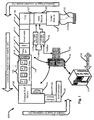
- FIG. 1 illustrates an exemplary block diagram for a mailpiece inserter system 100.
- the inserter system 100 assembles a mailpiece by accumulating sheets of a document, adding inserts, stuffing the document and inserts into an envelope and collecting the finished mailpieces for delivery to the postal authority. It is understood that inserter system 100 may be configured using alternative designs and still employ the technology disclosed herein. By way of example, inserter system 100 can be configured to include a right hand Turnover Sequence (TOS) and benefit from the disclosures herein. Inserter system 100 is configured to process 2-up sheets for creating a document, such as but not limited to a financial statement, invoice, advertisement, investment portfolio or prospectuses.
- TOS right hand Turnover Sequence
- the term 2-up refers to the roll of pre-printed paper or stack of pre-printed fan folded sheet paper 101 where two sheets are printed side by side on the roll of preprinted paper or on the stack of preprinted fan folded sheet paper 101.
- the dotted line 102 represents where the longitudinal first cut is performed whether the input paper is a roll or sheet.
- the dotted line represents a cut line and is not an indication that it is perforated.
- the horizontal cut performed by the cutter module 104 completes the separation of the two sheets from the roll or fan fold stack at which time they are transported to the hold module 106. Initially, before the horizontal cut, the two sheets are aligned exactly side by side, however due to the method employed to cut and transport the sheets to the hold module the cutter module 104 may output the two sheets with one leading or trailing the other.
- the hold module 106 measures this initial alignment and accounts for it in the process of adjusting the sheet alignment to be consistent with requirements of the downstream modules
- the sheet alignment process disclosed herein is applicable to processing larger width input paper, such as but not limited to, 3-up and 4-up configuration input paper configurations.
- the hold module 106 adjusts the sheets' alignment prior to entering the Turnover Sequencer (TOS) entry transport 107.
- the TOS entry transport 107 moves the two sheets from the hold module 106 into the TOS 108.
- the cut sheets of paper that make up the document move through the inserter in the direction indicated by arrow 10, as shown in FIG. 1 .
- the TOS 108 merges sheets S1-3 and S2-3 ( FIG. 3 ) which are entering the TOS from the TOS entry transport 107.
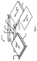
- the TOS illustrated in FIGS. 1 , 2 and 3 is a left hand 90 degree turn module.
- sheets S1-3 and S2-3 are in an offset position, when entering into the TOS 108, where the sheets enter the left 156 and right 155 open turnover tubes. These tubes are approximately one half open so that when sheets S1-3 and S2-3 are driven into the tubes they will curl on the inside surface. The curling action inverts each sheet and redirects them 90 degrees to the left in the direction of the TOS output transport 109.
- the TOS turnover tubes 156 and 155 are spaced apart by a distance 157 that corresponds to the width 158 of the sheet. This geometry makes the path length that sheet S2-3 travels longer than the path length for sheet S1-3 by a distance equal to the sheet width 158.
- Sheet S2-4 is on top of sheet S1-4 after they exit the TOS 108.
- the hold module's design for adjusting the alignment of two side by side sheets, to obtain the desired overlap distance (O-D), is explained below with reference to FIGS. 9 through 14 .
- the TOS output transport 109 moves the merged sheets S1-4 and S2-4 from the TOS 108 to the accumulator 110.
- the accumulator 110 collects all the sheets that form the pages of a document before passing the completed document to the folder 112.
- the folder 112 imparts the fold style required by the particular type of envelope used. The folder 112 may be bypassed if flat envelopes are used.
- the folder 112 outputs the document to the folder output transport 114 where the document is collected in the collector 118 at the input to the base assembly track 116.
- One or more insert feeders (IFS1 ...IFSN) 120 are located on the base assembly track 116 to add inserts to the material as the material for the mailpiece is moved down the base assembly track.
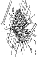
- FIG. 2 is an isometric view of the inserter hold module 106 through the accumulator 110 which is an exemplary illustration of these integrated functions.
- the position control system of inserter system's 100 hold module 106 is controlled by an inserter control computer 130. Movement of the sheets of a document through the hold module 106 are controlled by the servo master controller 135, which is a software module executed in the inserter control computer 130.
- the servo master controller 135 communicates position instructions to the right and left side servo drivers 137 and 136 via a fieldbus connection ( FIG. 1 ).
- the right and left side servo drivers 137 and 136 send the physical servo motor signals to the right and left servo motors 196 and 195 in the right side 265 and the left side 264 hold module transports, as shown in FIG. 4a .
- the software sheet position control requirements are defined in relationship to FIGS. 9 through 14 .
- Inserter job input parameters are received from the data center processor 131 and job results are sent by the computer 130 back to the data center processor 131.
- the data center processor 131 is network connected 132 to other inserters (not shown) and to other processing resources present in a document factory as may be required..
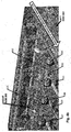
- the hold module 106 includes two independently driven transports.
- the left side transport 264 includes two input bottom belts 281 and 282 that are driven by pulleys (not shown), which are mounted on shaft 261.
- Two idler roller assemblies 287 and 288 capture sheet S1-1 against bottom belts 281 and 282.
- the left side transport 264 has an input roller assembly containing two additional idler rollers 293 and 294 on a single spring loaded shaft 295. Located on the shaft 295 is the sheet detection input photocell 252 for the left side transport 264.
- Belts 281 and 282 ( FIG.
- the right side transport 265 has an input roller assembly containing two additional idler rollers, 297 and 298 on a single spring loaded shaft 296. Located on the shaft 296 is the sheet detection input photocell 253 for the right side transport 265.
- Belts 284 and 286 ( FIG. 4a ), form a nip between the belt and the roller assembly which captures sheet S2-1 and pulls the sheet into the transport.
- a third set of idler assemblies 271 and 272 continue the positive transport control of sheet S1-1 through the hold module 106.
- the idler assembly 271 is driven by two rollers (input roller 270 and an output roller - not shown) attached to shafts 262 and 263. Idler rollers are mounted above the drive rollers to capture sheet S1-1 and transport the sheet without slippage.
- Idler assembly 272 is designed to be similar to idler assembly 271.
- the left side transport 264 is driven by servo motor 195 (not shown) that is connected to the primary drive pulley 260.
- the individual drive shafts 261, 262 and 263 are driven by a drive belt 159 that wraps around the primary drive pulley 260.
- the right side transport 265 is driven independently from the left side transport 264 by servo motor 196 (not visible in FIG. 4a ). All of the right side transport 265 components are the same as described for the left side transport 264. Shown in FIG. 4a are the bottom belts 284 and 286, two idler roller assemblies 289 and 290 and third set of idler assemblies 273 and 274. The right side transport 265 provides positive transport control of sheet S2-1 through the hold module 106.
- the left and right servo motors 195 and 196 are located under left and right side transports 264 and 265 and therefore are not visible in FIG. 4a .
- the identification arrows 195 and 196 show the approximate position of the servos under the transports.
- Each servo motor 195 and 196 is driven by a right and left independent servo drives 137, 136 which are controlled by the servo master controller 135 software in the inserter control computer 130 ( FIG. 1 ) .
- Integrated in each servo motor 195 and 196 is a high precision incremental encoder E1 and E2 ( FIG. 4a ) which the servo drive uses to measure the motor's angular displacement.
- the encoders E1 and E2 have a resolution of about 1,048,576 counts per motor revolution and each motor revolution transports sheets S1-1 and S2-1 150mm, via left and right side transports 264 and 265. This equates to about 6,990 encoder pulses per millimeter of travel.
- the servo master controller 135 utilizes this information to cyclically (i.e. a periodic rate) send each servo drive, 137 and 136, a commanded position to achieve the desired position change.
- the servo drive will then drive the servo motor to the commanded position before the next expected cyclic update.
- a new commanded position is sent to each servo drive at a 1 millisecond (ms) cycle.
- the velocity of the left and right side transports 264 and 265 is 5080 mm/sec or 200 in/sec when transporting sheets S1-1 and S1-2 into and out of the hold module 106.
- the servo master controller 135 increments the commanded position by 35512 each cycle.
- D ⁇ C Encoder counts per motor revolution mm per motor revolution ⁇ Velocity in mm / sec Fieldbus updates per second
- D ⁇ C 1 , 048 , 576 150 ⁇ 5 , 080 1 , 000
- D ⁇ C 35 , 512
- A-I can vary between each set of sheets due to slippage in the transfer from the cutter module 104 to the input rollers (293, 294; 297, 298) of the hold module 106.
- An incomplete cut may require the transport drive to rip the sheet from the cutter, causing a misalignment. Switching from roll to fan fold input paper also can effect alignment. Other reasons for misalignment out of the cutter can occur. However, the current disclosure can correct for the cutter alignment at the completion of every cut.
- the initial alignment may be a positive or negative.
- the lead edge alignment A-F has been created between sheets S1-1 and S2-1 which is consistent with the requirements needed to process the sheets in subsequent modules of the inserter 100.
- the hold module's 106 method of measuring the initial alignment A-I and adjusting the alignment of sheets S1-1 and S2-1 to get alignment A-F is explained in reference to FIGS. 9 through 14 .
- Error detection is accomplished upon exiting the hold module 106 by comparing predicted time of arrival with the measured time of arrival of the left and right sheets S1-3 and S2-3 respectively, as measured by photocells 254 and 255, located within idler assemblies 272 and 273 respectively ( FIG. 4a ). If the measured and predicted time of arrival do not match within a tolerance, an error condition exists that indicates a jam may have occurred in the hold module 106 or the sheet alignment is faulty which may cause a jam in subsequent modules.
- the hold module 106 does not perform any adjustment to the alignment while transporting them to the TOS entry transport 107.
- Sheets S1-3 and S2-3 remain perfectly aligned prior to entering the TOS 108.
- the sheets S1-4 and S2-4 then exit the TOS 108 overlapped (S2-4 is on top of S1-4) by distance O-I due to the path length difference through the TOS 108.
- the amount of overlap (O-I) is equal to the sheet length L minus the sheet width W.
- O ⁇ I L ⁇ W
- FIG. 6 illustrates the method employed by conventional system's to produce the desired overlap (O-D) of sheets S1-4 and S2-4 at the exit of the TOS 108.
- A-I 0
- a method is employed to change the sheet's lead edge alignment to (A-F) prior to entering the TOS 108.
- This alignment accounts for the TOS module 108 geometry and produces the desired overlap O-D of sheets S1-4 and S2-4 at the TOS exit.
- a ⁇ F O ⁇ D ⁇ O ⁇ I
- FIG. 7 illustrates again the method employed by conventional techniques, however with a nonzero initial alignment A-I.
- sheet S2-1 enters the hold module 106 ahead of sheet S1-1 by a distance A-I.
- the method to change the sheet's lead edge alignment to A-F is employed however, due to the initial alignment, the sheets enter the TOS 108 with an alignment equal to A-F plus A-I.
- the overlap of sheets S1-4 and S2-4 at the TOS exit become the desired overlap (O-D) plus the initial alignment (A-I) and thus they are not correctly overlapped for downstream processes.
- a method must be employed to measure the initial alignment (A-I) and account for it in the method employed to adjust the sheet's lead edge alignment to A-F prior to entering the TOS entry transport 107.
- This is illustrated in FIG. 8 , where sheets S1-1 and S2-1 are received with initial alignment A-I.
- the hold module 106 knowing the initial alignment (A-I), the servo master controller 135, adjusts the alignment by A-C while transporting them to the TOS entry transport 107.
- the result is that the sheets S1-3 and S2-3 lead edge alignment, prior to entering the TOS 108, is equal to A-F which will result in the correct desired overlap O-D between sheets S1-4 and S2-4 at the exit of the TOS module 108.
- a unique feature of the hold module 106 of the present application is its ability to measure and account for the initial alignment in the method employed to adjust sheets S1-1 and S2-1 lead edge alignment prior to entering a TOS 108.
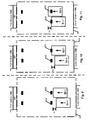
- FIG. 9 illustrates sheets S1-1 and S2-1; with initial alignment A-I, in the hold module 106 being transported at a constant and equal velocity towards photocells 252 and 253, respectively.
- the constant velocity of sheet S1-1 and S2-1 involves the servo master controller 135 cyclically sending the servo drives 136, 137 a commanded position which is incremented each cycle by D-C.
- the servo master controller 135 counts the number of encoder pulses received from encoder E2 from the time sheet S2-1 triggers photocell 253 until time sheet S1-1 triggers photocell 252 of servo motor 195 (E1).
- A-I is equal to the distance represented by each encoder pulse times the number of encoder pulses received between photocell triggers ( FIGS. 10 and 11 ).
- A-I will be negative if the sheet S1-2 with the longer travel path (this case the sheet on the right hand side) is trailing sheet S1-1 upon entering the hold module 106.
- the alignment correction (A-C) can be accurately calculated so that the sheets enter the TOS module 108 with alignment (A-F), to obtain the desired overlap (O-D) exiting the TOS module 108.
- a ⁇ C A ⁇ F ⁇ A ⁇ I
- both sheet S1-1 and S2-1 are advanced downstream by the same amount each period.
- the positional control by the servo master controller 135 is utilized to adjust sheets' S1-1 and S1-2 alignment to achieve A-F prior to entering the TOS 108 by changing the amount by which the servo drive's commanded position is incremented. It is desirable to employ this technique so as to maintain smooth paper handling. The change to the servo drives commanded position incremental value should be minimized.
- this is done by first dividing the relative amount to adjust (A-C) between the two servo drives, retarding one drive by approximately one half A-C and advancing the other by approximately one half A-C.
- the error tolerance in the division of the alignment correction A-C between transports allows for variation in the one half of A-C value from being exactly equal to one half..
- the number of cyclic updates (N) which adjustment is applied is calculated by dividing the time which it is possible to make this adjustment by the cyclic update period.
- the allowable time to perform an adjustment (e.g., 42 ms) in the hold module 106 is When sheets S1-2 and S2-2 are free of the cutter 104 and the TOS entry transport 107.
- FIG. 12 illustrates the sheets position as they move through the hold module 106 and the change in alignment for the first update.
- the left side transport 264 moves sheet S1-2 forward by a distance of (D-R) and the right side transport moves sheet S2-2 forward by a distance of (D-L).
- Subtracting (D-L) from (D-R) shows that the net change in the sheets alignment for each cyclic update is 2 (D-A).
- the net alignment change is 2N*(D-A) which is equivalent to the necessary alignment correction (A-C) required, giving initial alignment (A-I), to achieve the final alignment (A-F) prior to the TOS 108 to get the desired overlap (O-D) at the output.
- A-C necessary alignment correction
- A-I initial alignment
- A-F final alignment
- O-D desired overlap
- the D-A calculation involves returning an integer value however, in this case, if any remainder exists after the division then it is taken into account and handled with an additional fieldbus update.
- some of the word usage and such is in reference to a 90 degree left hand turn TOS module 108 configuration. All measurements and calculations work for other configurations, such as the Right Angle Turn (i.e. RAT) used conventionally, as well as initial alignments where sheet S1-1 is leading sheet S2-1.
- RAT Right Angle Turn
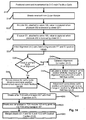
- FIG. 14 is an exemplary process flow chart to illustrate the control steps for the hold module 106.
- the control process begins with both servo motors 195 and 196 advancing sheets S1-1 and S2-1 at a constant incremental distance (D-C) each fieldbus update (S10). Sheets S1-1 and S2-1 move from the cutter module 104 into the hold module 106 at a steady state speed as defined by (D-C) position updates (S15). Photocells 252 and 253 are used to trigger a read of the value of encoders E1 and E2 when sheets S1-1 and S2-1 block each photocell 252 and 253 respectively (S20 and S25).
- step S30 the initial alignment (A-I) of sheets S1-1 and S2-1 is calculated based on the values of E1 and E2. In some rare cases, the initial alignment (A-I) equals the final alignment (A-F) (S35). When this occurs, there is no need to adjust the position update to produce additional offset between sheets S1-2 and S2-2.
- the servo master controller 135 sends, via cyclic fieldbus communication, the same position update (D-C) to each servo motor 195 and 196 (S45).
- the alignment correction (A-C) is calculated (S40).
- the relative change in servo position, per fieldbus command, 2*(D-A) required to achieve an Alignment Correction (A-C) after N field bus cycles may be calculated (step S42).
- an offset of (A-C) in position of sheets S1-3 and S2-3 is achieved (S43).
- the servo master controller 135 then sends (D-C) position updates to return sheets S1-2 and S2-2 to steady state speed prior to entering the TOS entry transport 107 (S45).
- the sheets S1-3 and S2-3 transfer to TOS entry transport 107 having alignment (A-F) (S50). Sheets S1-3 and S2-3 are transported from the exit of the hold module 106 to the TOS module 108 via the TOS entry transport 107 (S55). S1-4 and S2-4 are merged and overlapped by the desired overlap amount of (O-D) in the TOS module 108 (S60), and are ready for continued processing by the inserter system 100.
- functions relating pertain to the operation of an inserting system wherein hold module control is implemented in the hardware and controlled by one or more computers operating as the control processor 130 connected the inserting system and to a data center processor/server 131 for data communication with the processing resources as shown in FIG. 1 .
- special purpose devices may be used, such devices also may be implemented using one or more hardware platforms intended to represent a general class of data processing device commonly used to run "server” programming so as to implement the functions discussed above, albeit with an appropriate network connection for data communication.
- a general-purpose computer typically comprises a central processor or other processing device, an internal communication bus, various types of memory or storage media (RAM, ROM, EEPROM, cache memory, disk drives etc.) for code and data storage, and one or more network interface cards or ports for communication purposes.
- the software functionalities involve programming, including executable code as well as associated stored data.
- the software code is executable by the general-purpose computer that functions as the control processor 170 and/or the associated terminal device. In operation, the code is stored within the general-purpose computer platform. At other times, however, the software may be stored at other locations and/or transported for loading into the appropriate general-purpose computer system. Execution of such code by a processor of the computer platform enables the platform to implement the methodology for tracking of mail items through a postal authority network with reference to a specific mail target, in essentially the manner performed in the implementations discussed and illustrated herein.
- FIGS. 15 and 16 provide functional block diagram illustrations of general purpose computer hardware platforms.
- FIG. 15 illustrates a network or host computer platform, as may typically be used to implement a server.
- FIG. 16 depicts a computer with user interface elements, as may be used to implement a personal computer or other type of work station or terminal device, although the computer of FIG. 16 may also act as a server if appropriately programmed. It is believed that those skilled in the art are familiar with the structure, programming and general operation of such computer equipment and, as a result, the drawings should be self-explanatory.
- control processor 130 may be a PC based implementation of a central control processing system like that of FIG. 16 , or may be implemented on a platform configured as a central or host computer or server like that of FIG. 15 .
- a system typically contains a central processing unit (CPU), memories and an interconnect bus.
- the CPU may contain a single microprocessor (e.g. a Pentium microprocessor), or it may contain a plurality of microprocessors for configuring the CPU as a multi-processor system.
- the memories include a main memory, such as a dynamic random access memory (DRAM) and cache, as well as a read only memory, such as a PROM, an EPROM, a FLASH-EPROM or the like.
- the system memories also include one or more mass storage devices such as various disk drives, tape drives, etc.
- the main memory stores at least portions of instructions for execution by the CPU and data for processing in accord with the executed instructions, for example, as uploaded from mass storage.
- the mass storage may include one or more magnetic disk or tape drives or optical disk drives, for storing data and instructions for use by CPU.
- at least one mass storage system in the form of a disk drive or tape drive stores the operating system and various application software.
- the mass storage within the computer system may also include one or more drives for various portable media, such as a floppy disk, a compact disc read only memory (CD-ROM), or an integrated circuit non-volatile memory adapter (i.e. PC-MCIA adapter) to input and output data and code to and from the computer system.
- PC-MCIA adapter integrated circuit non-volatile memory adapter
- the system also includes one or more input/output interfaces for communications, shown by way of example as an interface for data communications with one or more other processing systems. Although not shown, one or more such interfaces may enable communications via a network, e.g., to enable sending and receiving instructions electronically.
- the physical communication links may be optical, wired, or wireless.
- the computer system may further include appropriate input/output ports for interconnection with a display and a keyboard serving as the respective user interface for the processor/controller.
- a printer control computer in a document factory may include a graphics subsystem to drive the output display.
- the output display for example, may include a cathode ray tube (CRT) display, or a liquid crystal display (LCD) or other type of display device.
- the input control devices for such an implementation of the system would include the keyboard for inputting alphanumeric and other key information.
- the input control devices for the system may further include a cursor control device (not shown), such as a mouse, a touchpad, a trackball, stylus, or cursor direction keys.
- the links of the peripherals to the system may be wired connections or use wireless communications.
- the computer system runs a variety of applications programs and stores data, enabling one or more interactions via the user interface provided, and/or over a network to implement the desired processing, in this case, including those for tracking of mail items through a postal authority network with reference to a specific mail target, as discussed above.
- the components contained in the computer system are those typically found in general purpose computer systems. Although summarized in the discussion above mainly as a PC type implementation, those skilled in the art will recognize that the class of applicable computer systems also encompasses systems used as host computers, servers, workstations, network terminals, and the like. In fact, these components are intended to represent a broad category of such computer components that are well known in the art. The present examples are not limited to any one network or computing infrastructure model-i.e., peer-to-peer, client server, distributed, etc.
- aspects of the techniques discussed herein encompass hardware and programmed equipment for controlling the relevant document processing as well as software programming, for controlling the relevant functions.
- a software or program product which may be referred to as a "program article of manufacture” may take the form of code or executable instructions for causing a computer or other programmable equipment to perform the relevant data processing steps, where the code or instructions are carried by or otherwise embodied in a medium readable by a computer or other machine. Instructions or code for implementing such operations may be in the form of computer instruction in any form (e.g., source code, object code, interpreted code, etc.) stored in or carried by any readable medium.
- Such a program article or product therefore takes the form of executable code and/or associated data that is carried on or embodied in a type of machine readable medium.
- "Storage" type media include any or all of the memory of the computers, processors or the like, or associated modules thereof, such as various semiconductor memories, tape drives, disk drives and the like, which may provide non-transitory storage at any time for the software programming. All or portions of the software may at times be communicated through the Internet or various other telecommunication networks. Such communications, for example, may enable loading of the relevant software from one computer or processor into another, for example, from a management server or host computer into the image processor and comparator.
- another type of media that may bear the software elements includes optical, electrical and electromagnetic waves, such as used across physical interfaces between local devices, through wired and optical landline networks and over various air-links.
- the physical elements that carry such waves, such as wired or wireless links, optical links or the like, also may be considered as media bearing the software.
- terms such as computer or machine "readable medium” refer to any medium that participates in providing instructions to a processor for execution.
- a machine readable medium may take many forms, including but not limited to, a tangible storage medium, a carrier wave medium or physical transmission medium.
- Non-volatile storage media include, for example, optical or magnetic disks, such as any of the storage devices in any computer(s) or the like.
- Volatile storage media include dynamic memory, such as main memory of such a computer platform.
- Tangible transmission media include coaxial cables; copper wire and fiber optics, including the wires that comprise a bus within a computer system.
- Carrier-wave transmission media can take the form of electric or electromagnetic signals, or acoustic or light waves such as those generated during radio frequency (RF) and infrared (IR) data communications.
- RF radio frequency
- IR infrared
- Computer-readable media therefore include for example: a floppy disk, a flexible disk, hard disk, magnetic tape, any other magnetic medium, a CD-ROM, DVD or DVD-ROM, any other optical medium, punch cards paper tape, any other physical storage medium with patterns of holes, a RAM, a PROM and EPROM, a FLASH-EPROM, any other memory chip or cartridge, a carrier wave transporting data or instructions, cables or links transporting such a carrier wave, or any other medium from which a computer can read programming code and/or data. Many of these forms of computer readable media may be involved in carrying one or more sequences of one or more instructions to a processor for execution.
Landscapes
- Engineering & Computer Science (AREA)
- Mechanical Engineering (AREA)
- Registering Or Overturning Sheets (AREA)
Claims (15)
- Einsetzsystem (100), das dazu ausgebildet ist, die eine Ausrichtung von mehreren Papierblättern (S1, S2), die insbesondere von einem Schneidemodul (104) ausgegeben wurden, zu regulieren, wobei das Einsetzsystem Folgendes umfasst:ein Haltemodul (106), das stromabwärts von einem vorhergehenden Modul, insbesondere dem Schneidemodul (104), positioniert ist, wobei das Haltemodul (106)mehrere parallele Blatttransportmittel (264, 265) aufweist, um die Papierblätter (S1, S2) parallel zu transportieren;dadurch gekennzeichnet, dass das Haltemodul (106) fernermehrere Servomotoren (195, 196), die dazu ausgebildet sind, jedes Blatttransportmittel (264, 265) anzutreiben, wobei jeder Servomotor (195, 196) mit einem Codierer (E1, E2) gekoppelt ist, der dazu ausgebildet ist, mit jeder Umdrehung der Servomotoren (195, 196) Codiererimpulse zu erzeugen;einen ersten und einen zweiten Sensor, insbesondere Lichtsensoren (252, 253), die dazu ausgebildet sind, das Vorhandensein eines ersten und eines zweiten Blatts (S1, S2) an jeweiligen Blatttransportmittel-Zugangspunkten zu detektieren; undeinen Einsetzsystemsteuercomputer (130), der dazu programmiert ist, eine Ausrichtungskorrekturdistanz (A-C) zwischen dem ersten und dem zweiten Blatt (S1, S2) in dem Haltemodul (106) zu berechnen, um Anforderungen eines oder mehrerer Module (108, 110, 112, 118, 120, 122), die sich stromabwärts von dem Haltemodul (106) befinden, zu berücksichtigen, aufweist, wobei der Systemsteuercomputer (130) dazu ausgebildet ist,auf Basis eines Unterscheid zwischen den Codiererimpulsen, die zwischen einer ersten Detektion des ersten Blatts (S1) durch den ersten Sensor (252) auf dem ersten Transportmittel (264) und einer Detektion des zweiten Blatts (S2) durch den zweiten Sensor (253) auf dem zweiten Transportmittel (265) erhalten wurden, einen anfänglichen Ausrichtungsversatz (A-I) zwischen dem ersten und dem zweiten Blatt (S1, S2) zu berechnen,erstellte Blattausrichtungsanforderungen (O-D, A-F) des einen oder der mehreren Module (108, 110, 112, 114), die sich stromabwärts von dem Haltemodal (106) befinden, zu erhalten,eine Ausrichtungskorrekturdistanz (A-C) zu berechnen, undfür jede zyklische Positionsaktualisierung, die zu jedem Servomotor (195, 196) gesendet wird, eine Distanz, über die jedes Blatt in dem Haltemodul (106) transportiert werden soll, zu steuern.
- Einsetzsystem nach Anspruch 1, wobei das erste und das zweite Blatttransportmittel (264, 265) durch den ersten und den zweiten Servomotor (136, 137) jeweils gesondert angetrieben werden.
- Einsetzsystem nach einem der vorhergehenden Ansprüche, ferner umfassend:eine Servomastersteuerung (135), die dem Einsetzersystemsteuercomputer (130) zugehörig ist, wobei die Servomastersteuerung (135) dazu ausgebildet ist, für jede zyklische Positionsaktualisierung eine unterschiedliche Positionierungsaktualisierung zu jedem aus dem ersten und dem zweiten Transportmittel (264, 265) zu senden.
- Einsetzsystem nach einem der vorhergehenden Ansprüche, wobei das eine oder die mehreren Module, die sich stromabwärts von dem Haltemodul befinden, eine Sammeleinrichtung (110), eine Falteinrichtung (112) oder einen Wendesequenzer (108) beinhalten.
- Einsetzsystem nach einem der vorhergehenden Ansprüche, wobei die berechnete Korrekturausrichtungsdistanz (A-C) zwischen dem ersten und dem zweiten Transportpfad (264, 265) aufgeteilt wird, bevor das erste und das zweite Blatt das eine oder die mehreren Module (108, 110, 112, 114), die sich stromabwärts von dem Haltemodul (106) befinden, betreten.
- Einsetzsystem zumindest nach Anspruch 3, wobei Blattpositionsbefehle von der Masterservosteuerung (135) für das erste oder das zweite Transportmittel (264, 265), das ein stromabwärts befindliches Modul (108, 110, 112, 114) über eine längere Pfadlänge versorgt, größer sind als die zyklische Positionsaktualisierung für die Positionsaktualisierung beim Transport im stabilen Zustand vor dem Betreten des einen oder der mehreren Module (108, 110, 112, 114), die sich stromabwärts von dem Haltemodul (106) befinden,
und/oder
wobei Blattpositionsbefehle von der Masterservosteuerung (135) für das erste oder das zweite Transportmittel (264, 265), das ein stromabwärts befindliches Modul (108, 110, 112, 114) über eine kürzere Pfadlänge versorgt, kleiner sind als die zyklische Positionsaktualisierung für die Positionsaktualisierung beim Transport im stabilen Zustand vor dem Betreten des einen oder der mehreren Module (108, 110, 112, 114), die sich stromabwärts von dem Haltemodul (106) befinden. - Einsetzsystem nach einem der vorhergehenden Ansprüche, wobei die Ausrichtungskorrekturdistanz (A-C), die nötig ist, um den endgültigen Ausrichtungsversatz (A-F), der von dem einen oder den der mehreren Modulen (110, 112, 118), die sich stromabwärts von dem Haltemodul (106) befinden, benötigt wird, zu erhalten, eine Funktion eines gemessenen anfänglichen Ausrichtungsversatzes (A-I) an dem Eingang in das Haltemodul (106) und eines Versatzes (O-D) zwischen dem ersten und dem zweiten Blatt (S1, S2), der von den stromabwärts von dem Haltemodul (106) befindlichen Module benötigt wird, ist.
- Einsetzsystem nach einem der vorhergehenden Ansprüche, wobei die berechnete Ausrichtungskorrekturdistanz (A-C) gleichmäßig zwischen dem ersten und dem zweiten Servomotor (195, 196) aufgeteilt wird, so dass der erste Servomotor (195) um ungefähr eine Hälfte verzögert wird und der zweite Servomotor (196) um ungefähr eine Hälfte vorgerückt wird.
- Einsetzsystem nach einem der vorhergehenden Ansprüche, wobei eine Anzahl von zyklischen Positionsaktualisierungen, über die die berechnete Ausrichtungskorrekturdistanz (A-C) angewendet wird, durch Teilen der Zeit berechnet wird, wodurch es möglich ist, die Korrektur durch den zyklischen Positionsaktualisierungszeitraum vorzunehmen.
- Verfahren zum Ausrichten von mehreren Blättern (S1, S2), die durch ein Einsetzsystem (100) parallel verarbeitet werden, wobei das Verfahren einen Schritt des
Transportierens eines ersten und eines zweiten Blatts (S1, S2) durch ein erstes und ein zweites paralleles Transportmittel (264, 265) eines Haltemoduls (106) des Einsetzsystems (100) umfasst, dadurch gekennzeichnet, dass es ferner die folgenden Schritte umfasst:Erhalten von Sensorauslösungen von einem ersten und einem zweiten Sensor (252, 253), insbesondere Photozellen (252, 253), und Codiererimpulswerten von einem ersten und einem zweiten Codierer (E1, E2), die an dem ersten und dem zweiten Transportmittel (264, 265) in dem Haltemodul (106) positioniert sind, während das erste und das zweite Blatt (S1, S2) durch das Haltemodul (106) transportiert werden;Berechnen eines anfänglichen Ausrichtungsversatzes (A-I) zwischen dem ersten und dem zweiten Blatt (S1, S2) durch Zählen einer Anzahl von Codiererimpulsen, die von dem ersten Codierer (E1) von einer ersten Zeit, zu der das erste Blatt (S1) den ersten Sensor (252) auslöst, bis zu einer zweiten Zeit, zu der das zweite Blatt (S2) den zweiten Sensor (253) auslöst, erhalten werden;Aufteilen des Ausmaßes der Ausrichtungskorrekturdistanz (A-C) zwischen dem ersten und dem zweiten Blatt (S1, S2) zwischen einem ersten Servomotor (195), der dem Pfad des ersten Transportmittels (264) zugehörig ist, und einem zweiten Servomotor (196), der dem Pfad des zweiten Transportmittels (265) zugehörig ist, auf Basis von Anforderungen eines oder mehrerer anschließende Module (108, 110, 112, 114), die sich stromabwärts von dem Haltemodul (106) befinden; undAntreiben des ersten Servomotors (195), um eine erste Distanz, die durch das erste Blatt auf dem Pfad des ersten Transportmittels (264) zurückgelegt wird, für jede zyklische Positionsaktualisierung, die zu dem ersten Servomotor (195) gesendet wird, einzustellen, und Antreiben des zweiten Servomotors (196), um eine zweite Distanz, die durch das zweite Blatt auf dem Pfad des zweiten Transportmittels (265) zurückgelegt wird, für jede zyklische Positionsaktualisierung, die zu dem zweiten Servomotor (196) gesendet wird, einzustellen,wobei eine Gesamtanzahl der zyklischen Positionsaktualisierungen, die zu jedem Servomotor (195, 196) gesendet werden, zu einem Bewegen des ersten und des zweiten Blatts (S1, S2) durch das Haltemodul (106) führt, während eine Versatzdistanz zwischen dem ersten und dem zweiten Blatt (S1, S2) vermittelt wird. - Verfahren nach dem vorhergehenden Anspruch, wobei das Antreiben des ersten und des zweiten Servomotors (195, 196) einen Blattversatz (A-F, O-D) zwischen dem ersten und dem zweiten Blatt (S1, S2) vermittelt, der von einen oder mehreren stromabwärts von dem Haltemodul (106) befindlichen Modulen (108, 110, 112, 114), die eine Sammeleinrichtung (110), eine Falteinrichtung (112) oder einen Wendesequenzer (108) beinhalten, benötigt wird.
- Verfahren nach einem der Ansprüche 10 oder 11, wobei von der Servomastersteuerung (135) für das erste oder zweite Transportmittel (264, 265) zyklische Positionsbefehle für den Transportmittelservomotor (195, 196) gesendet werden, wobei die zyklischen Positionsbefehle für das Transportmittel, das das Blatt enthält, welches beim endgültigen Versatz nachläuft, kleiner als die zyklischen Positionsaktualisierungen im stabilen Zustand sind,
und/oder
wobei die zyklischen Positionsbefehle für das Transportmittel, das das Blatt enthält, welches beim endgültigen Versatz vorläuft, größer als die zyklischen Positionsaktualisierungen im stabilen Zustand sind. - Verfahren nach einem der Ansprüche 10 bis 12, wobei die berechnete Ausrichtungskorrekturdistanz (A-C), die zu dem ersten und dem zweiten Servomotor (195, 196) gesendet wird, gleichmäßig zwischen dem ersten und dem zweiten Servomotor (195, 196) aufgeteilt wird, so dass der erste Servomotor (195) um ungefähr eine Hälfte verzögert wird und der zweite Servomotor (196) um ungefähr eine Hälfte vorgerückt wird.
- Verfahren nach einem der Ansprüche 10 bis 13, wobei die gesamte Anzahl der zyklischen Positionsaktualisierungen, die mit der Ausrichtungskorrekturdistanz (A-C) verbunden sind, welche zu den Servomotorantrieben für den ersten und den zweiten Transportmittelservomotor (195, 196) gesendet wird, durch die Anzahl der zyklischen Positionsaktualisierungen, die auftreten, während zwischen dem ersten und dem zweiten Blatt (S1, S2) eine Versatzdistanz vermittelt wird, geteilt wird.
- Verfahren nach einem der Ansprüche 10 bis 14, wobei die berechnete Ausrichtungskorrekturdistanz (A-C) zwischen dem ersten und dem zweiten Blatt (S1, S2), die durch das Haltemodul (106) vermittelt wird, eine Funktion der Anforderung eines oder mehrerer stromabwärts von dem Haltemodul (106) befindlicher Module (108, 110, 112, 114) ist, die eine Sammeleinrichtung (110), eine Falteinrichtung (112) oder einen Wendesequenzer (108) beinhalten.
Applications Claiming Priority (2)
| Application Number | Priority Date | Filing Date | Title |
|---|---|---|---|
| US201361903734P | 2013-11-13 | 2013-11-13 | |
| US14/529,053 US9540203B2 (en) | 2013-11-13 | 2014-10-30 | Method and system for synchronizing items using position compensation |
Publications (2)
| Publication Number | Publication Date |
|---|---|
| EP2876069A1 EP2876069A1 (de) | 2015-05-27 |
| EP2876069B1 true EP2876069B1 (de) | 2016-09-21 |
Family
ID=51900742
Family Applications (1)
| Application Number | Title | Priority Date | Filing Date |
|---|---|---|---|
| EP14192784.8A Active EP2876069B1 (de) | 2013-11-13 | 2014-11-12 | Kuvertiersystem und Verfahren zur Ausrichtung von Bögen |
Country Status (2)
| Country | Link |
|---|---|
| US (1) | US9540203B2 (de) |
| EP (1) | EP2876069B1 (de) |
Cited By (1)
| Publication number | Priority date | Publication date | Assignee | Title |
|---|---|---|---|---|
| US9540203B2 (en) | 2013-11-13 | 2017-01-10 | Bell And Howell, Llc | Method and system for synchronizing items using position compensation |
Families Citing this family (1)
| Publication number | Priority date | Publication date | Assignee | Title |
|---|---|---|---|---|
| CN111193865B (zh) * | 2019-12-31 | 2021-08-03 | 维沃移动通信有限公司 | 图像处理方法和装置 |
Citations (1)
| Publication number | Priority date | Publication date | Assignee | Title |
|---|---|---|---|---|
| US6764070B2 (en) * | 2002-10-25 | 2004-07-20 | Pitneybowes Inc. | Pathlength compensation method and device for high speed sheet cutters |
Family Cites Families (5)
| Publication number | Priority date | Publication date | Assignee | Title |
|---|---|---|---|---|
| DE3920417A1 (de) * | 1989-06-22 | 1991-01-03 | Bielomatik Leuze & Co | Sortiereinrichtung fuer flaechige zuschnitte |
| US6443447B1 (en) | 2000-12-29 | 2002-09-03 | Pitney Bowes Inc. | Method and device for moving cut sheets in a sheet accumulating system |
| US6435331B1 (en) * | 2001-03-16 | 2002-08-20 | Lockheed Martin Corporation | Dynamic gap establishing synchronous product insertion system |
| US7752948B2 (en) | 2006-12-01 | 2010-07-13 | Pitney Bowes Inc. | Method and apparatus for enhanced cutter throughput using an exit motion profile |
| US9540203B2 (en) | 2013-11-13 | 2017-01-10 | Bell And Howell, Llc | Method and system for synchronizing items using position compensation |
-
2014
- 2014-10-30 US US14/529,053 patent/US9540203B2/en active Active
- 2014-11-12 EP EP14192784.8A patent/EP2876069B1/de active Active
Patent Citations (1)
| Publication number | Priority date | Publication date | Assignee | Title |
|---|---|---|---|---|
| US6764070B2 (en) * | 2002-10-25 | 2004-07-20 | Pitneybowes Inc. | Pathlength compensation method and device for high speed sheet cutters |
Cited By (1)
| Publication number | Priority date | Publication date | Assignee | Title |
|---|---|---|---|---|
| US9540203B2 (en) | 2013-11-13 | 2017-01-10 | Bell And Howell, Llc | Method and system for synchronizing items using position compensation |
Also Published As
| Publication number | Publication date |
|---|---|
| US20150130126A1 (en) | 2015-05-14 |
| US9540203B2 (en) | 2017-01-10 |
| EP2876069A1 (de) | 2015-05-27 |
Similar Documents
| Publication | Publication Date | Title |
|---|---|---|
| US6644660B2 (en) | Dynamic pitch correction for an output inserter subsystem | |
| US9919443B2 (en) | Systems, methods, and computer readable media for sheet registration in a tractorless sheet processing device using at least one existing sheet feature | |
| EP0077454B1 (de) | Blattzuführ- und Ausrichtvorrichtung | |
| US9352872B2 (en) | Method and system to print and apply labels to products | |
| EP2660175A2 (de) | Verfahren und System für halbautomatische Schalenbeladungsvorrichtung | |
| US7631869B2 (en) | System and method for gap length measurement and control | |
| EP2876069B1 (de) | Kuvertiersystem und Verfahren zur Ausrichtung von Bögen | |
| EP2119651A2 (de) | Automatisches Zubringerkontrollsystem zur Berücksichtigung von Eingabevariationen | |
| EP1388820B1 (de) | Verfahren und System zum schnellen digitalen Frankieren unter Verwendung einer langsamen Drucktechnik | |
| US9827798B2 (en) | Assemblies, systems, and methods for applying postage indicia to one or more mailpiece on a high speed mail sorter | |
| US8814491B2 (en) | Method and system for mail item turnover | |
| US8972046B2 (en) | Feed station for feeding flat items to a processing apparatus | |
| US6601364B2 (en) | Method and device for synchronizing motion for insert feeders in an insertion system | |
| AU2010234569B2 (en) | Apparatus and method to control material converting and envelope stuffing | |
| US20140150378A1 (en) | Inter-machine buffer for mailpiece fabrication system | |
| US6863273B2 (en) | Document handling apparatus with dynamic infeed mechanism and related method | |
| US7232125B2 (en) | Device for collating laminar workpieces | |
| US20160243884A1 (en) | Method of controlling insertion depth of a moving collation into an accelerating envelope | |
| US8038150B2 (en) | Sheet thickness measurement | |
| CN204607145U (zh) | 片状物姿态校正装置 | |
| JPS6279115A (ja) | ピツチ搬送制御装置 |
Legal Events
| Date | Code | Title | Description |
|---|---|---|---|
| PUAI | Public reference made under article 153(3) epc to a published international application that has entered the european phase |
Free format text: ORIGINAL CODE: 0009012 |
|
| 17P | Request for examination filed |
Effective date: 20141112 |
|
| AK | Designated contracting states |
Kind code of ref document: A1 Designated state(s): AL AT BE BG CH CY CZ DE DK EE ES FI FR GB GR HR HU IE IS IT LI LT LU LV MC MK MT NL NO PL PT RO RS SE SI SK SM TR |
|
| AX | Request for extension of the european patent |
Extension state: BA ME |
|
| R17P | Request for examination filed (corrected) |
Effective date: 20150625 |
|
| RBV | Designated contracting states (corrected) |
Designated state(s): AL AT BE BG CH CY CZ DE DK EE ES FI FR GB GR HR HU IE IS IT LI LT LU LV MC MK MT NL NO PL PT RO RS SE SI SK SM TR |
|
| GRAP | Despatch of communication of intention to grant a patent |
Free format text: ORIGINAL CODE: EPIDOSNIGR1 |
|
| RIC1 | Information provided on ipc code assigned before grant |
Ipc: B65H 39/06 20060101ALI20160322BHEP Ipc: B65H 29/12 20060101AFI20160322BHEP Ipc: B65H 29/52 20060101ALI20160322BHEP Ipc: B65H 43/02 20060101ALI20160322BHEP |
|
| INTG | Intention to grant announced |
Effective date: 20160425 |
|
| GRAS | Grant fee paid |
Free format text: ORIGINAL CODE: EPIDOSNIGR3 |
|
| GRAA | (expected) grant |
Free format text: ORIGINAL CODE: 0009210 |
|
| AK | Designated contracting states |
Kind code of ref document: B1 Designated state(s): AL AT BE BG CH CY CZ DE DK EE ES FI FR GB GR HR HU IE IS IT LI LT LU LV MC MK MT NL NO PL PT RO RS SE SI SK SM TR |
|
| REG | Reference to a national code |
Ref country code: GB Ref legal event code: FG4D |
|
| REG | Reference to a national code |
Ref country code: CH Ref legal event code: EP |
|
| REG | Reference to a national code |
Ref country code: AT Ref legal event code: REF Ref document number: 830867 Country of ref document: AT Kind code of ref document: T Effective date: 20161015 |
|
| REG | Reference to a national code |
Ref country code: IE Ref legal event code: FG4D |
|
| REG | Reference to a national code |
Ref country code: DE Ref legal event code: R096 Ref document number: 602014003806 Country of ref document: DE |
|
| REG | Reference to a national code |
Ref country code: FR Ref legal event code: PLFP Year of fee payment: 3 |
|
| REG | Reference to a national code |
Ref country code: LT Ref legal event code: MG4D Ref country code: NL Ref legal event code: MP Effective date: 20160921 |
|
| PG25 | Lapsed in a contracting state [announced via postgrant information from national office to epo] |
Ref country code: LT Free format text: LAPSE BECAUSE OF FAILURE TO SUBMIT A TRANSLATION OF THE DESCRIPTION OR TO PAY THE FEE WITHIN THE PRESCRIBED TIME-LIMIT Effective date: 20160921 Ref country code: FI Free format text: LAPSE BECAUSE OF FAILURE TO SUBMIT A TRANSLATION OF THE DESCRIPTION OR TO PAY THE FEE WITHIN THE PRESCRIBED TIME-LIMIT Effective date: 20160921 Ref country code: RS Free format text: LAPSE BECAUSE OF FAILURE TO SUBMIT A TRANSLATION OF THE DESCRIPTION OR TO PAY THE FEE WITHIN THE PRESCRIBED TIME-LIMIT Effective date: 20160921 Ref country code: HR Free format text: LAPSE BECAUSE OF FAILURE TO SUBMIT A TRANSLATION OF THE DESCRIPTION OR TO PAY THE FEE WITHIN THE PRESCRIBED TIME-LIMIT Effective date: 20160921 Ref country code: NO Free format text: LAPSE BECAUSE OF FAILURE TO SUBMIT A TRANSLATION OF THE DESCRIPTION OR TO PAY THE FEE WITHIN THE PRESCRIBED TIME-LIMIT Effective date: 20161221 |
|
| REG | Reference to a national code |
Ref country code: AT Ref legal event code: MK05 Ref document number: 830867 Country of ref document: AT Kind code of ref document: T Effective date: 20160921 |
|
| PG25 | Lapsed in a contracting state [announced via postgrant information from national office to epo] |
Ref country code: GR Free format text: LAPSE BECAUSE OF FAILURE TO SUBMIT A TRANSLATION OF THE DESCRIPTION OR TO PAY THE FEE WITHIN THE PRESCRIBED TIME-LIMIT Effective date: 20161222 Ref country code: NL Free format text: LAPSE BECAUSE OF FAILURE TO SUBMIT A TRANSLATION OF THE DESCRIPTION OR TO PAY THE FEE WITHIN THE PRESCRIBED TIME-LIMIT Effective date: 20160921 Ref country code: LV Free format text: LAPSE BECAUSE OF FAILURE TO SUBMIT A TRANSLATION OF THE DESCRIPTION OR TO PAY THE FEE WITHIN THE PRESCRIBED TIME-LIMIT Effective date: 20160921 Ref country code: BE Free format text: LAPSE BECAUSE OF NON-PAYMENT OF DUE FEES Effective date: 20161130 Ref country code: SE Free format text: LAPSE BECAUSE OF FAILURE TO SUBMIT A TRANSLATION OF THE DESCRIPTION OR TO PAY THE FEE WITHIN THE PRESCRIBED TIME-LIMIT Effective date: 20160921 |
|
| PG25 | Lapsed in a contracting state [announced via postgrant information from national office to epo] |
Ref country code: RO Free format text: LAPSE BECAUSE OF FAILURE TO SUBMIT A TRANSLATION OF THE DESCRIPTION OR TO PAY THE FEE WITHIN THE PRESCRIBED TIME-LIMIT Effective date: 20160921 Ref country code: EE Free format text: LAPSE BECAUSE OF FAILURE TO SUBMIT A TRANSLATION OF THE DESCRIPTION OR TO PAY THE FEE WITHIN THE PRESCRIBED TIME-LIMIT Effective date: 20160921 |
|
| PG25 | Lapsed in a contracting state [announced via postgrant information from national office to epo] |
Ref country code: AT Free format text: LAPSE BECAUSE OF FAILURE TO SUBMIT A TRANSLATION OF THE DESCRIPTION OR TO PAY THE FEE WITHIN THE PRESCRIBED TIME-LIMIT Effective date: 20160921 Ref country code: ES Free format text: LAPSE BECAUSE OF FAILURE TO SUBMIT A TRANSLATION OF THE DESCRIPTION OR TO PAY THE FEE WITHIN THE PRESCRIBED TIME-LIMIT Effective date: 20160921 Ref country code: BG Free format text: LAPSE BECAUSE OF FAILURE TO SUBMIT A TRANSLATION OF THE DESCRIPTION OR TO PAY THE FEE WITHIN THE PRESCRIBED TIME-LIMIT Effective date: 20161221 Ref country code: BE Free format text: LAPSE BECAUSE OF FAILURE TO SUBMIT A TRANSLATION OF THE DESCRIPTION OR TO PAY THE FEE WITHIN THE PRESCRIBED TIME-LIMIT Effective date: 20160921 Ref country code: SM Free format text: LAPSE BECAUSE OF FAILURE TO SUBMIT A TRANSLATION OF THE DESCRIPTION OR TO PAY THE FEE WITHIN THE PRESCRIBED TIME-LIMIT Effective date: 20160921 Ref country code: SK Free format text: LAPSE BECAUSE OF FAILURE TO SUBMIT A TRANSLATION OF THE DESCRIPTION OR TO PAY THE FEE WITHIN THE PRESCRIBED TIME-LIMIT Effective date: 20160921 Ref country code: IS Free format text: LAPSE BECAUSE OF FAILURE TO SUBMIT A TRANSLATION OF THE DESCRIPTION OR TO PAY THE FEE WITHIN THE PRESCRIBED TIME-LIMIT Effective date: 20170121 Ref country code: PT Free format text: LAPSE BECAUSE OF FAILURE TO SUBMIT A TRANSLATION OF THE DESCRIPTION OR TO PAY THE FEE WITHIN THE PRESCRIBED TIME-LIMIT Effective date: 20170123 Ref country code: CZ Free format text: LAPSE BECAUSE OF FAILURE TO SUBMIT A TRANSLATION OF THE DESCRIPTION OR TO PAY THE FEE WITHIN THE PRESCRIBED TIME-LIMIT Effective date: 20160921 Ref country code: PL Free format text: LAPSE BECAUSE OF FAILURE TO SUBMIT A TRANSLATION OF THE DESCRIPTION OR TO PAY THE FEE WITHIN THE PRESCRIBED TIME-LIMIT Effective date: 20160921 |
|
| REG | Reference to a national code |
Ref country code: DE Ref legal event code: R097 Ref document number: 602014003806 Country of ref document: DE |
|
| PLBE | No opposition filed within time limit |
Free format text: ORIGINAL CODE: 0009261 |
|
| STAA | Information on the status of an ep patent application or granted ep patent |
Free format text: STATUS: NO OPPOSITION FILED WITHIN TIME LIMIT |
|
| PG25 | Lapsed in a contracting state [announced via postgrant information from national office to epo] |
Ref country code: DK Free format text: LAPSE BECAUSE OF FAILURE TO SUBMIT A TRANSLATION OF THE DESCRIPTION OR TO PAY THE FEE WITHIN THE PRESCRIBED TIME-LIMIT Effective date: 20160921 |
|
| REG | Reference to a national code |
Ref country code: IE Ref legal event code: MM4A |
|
| 26N | No opposition filed |
Effective date: 20170622 |
|
| PG25 | Lapsed in a contracting state [announced via postgrant information from national office to epo] |
Ref country code: LU Free format text: LAPSE BECAUSE OF NON-PAYMENT OF DUE FEES Effective date: 20161130 |
|
| REG | Reference to a national code |
Ref country code: FR Ref legal event code: PLFP Year of fee payment: 4 |
|
| PG25 | Lapsed in a contracting state [announced via postgrant information from national office to epo] |
Ref country code: SI Free format text: LAPSE BECAUSE OF FAILURE TO SUBMIT A TRANSLATION OF THE DESCRIPTION OR TO PAY THE FEE WITHIN THE PRESCRIBED TIME-LIMIT Effective date: 20160921 Ref country code: IE Free format text: LAPSE BECAUSE OF NON-PAYMENT OF DUE FEES Effective date: 20161112 |
|
| PG25 | Lapsed in a contracting state [announced via postgrant information from national office to epo] |
Ref country code: HU Free format text: LAPSE BECAUSE OF FAILURE TO SUBMIT A TRANSLATION OF THE DESCRIPTION OR TO PAY THE FEE WITHIN THE PRESCRIBED TIME-LIMIT; INVALID AB INITIO Effective date: 20141112 |
|
| PG25 | Lapsed in a contracting state [announced via postgrant information from national office to epo] |
Ref country code: MK Free format text: LAPSE BECAUSE OF FAILURE TO SUBMIT A TRANSLATION OF THE DESCRIPTION OR TO PAY THE FEE WITHIN THE PRESCRIBED TIME-LIMIT Effective date: 20160921 Ref country code: CY Free format text: LAPSE BECAUSE OF FAILURE TO SUBMIT A TRANSLATION OF THE DESCRIPTION OR TO PAY THE FEE WITHIN THE PRESCRIBED TIME-LIMIT Effective date: 20160921 Ref country code: MC Free format text: LAPSE BECAUSE OF FAILURE TO SUBMIT A TRANSLATION OF THE DESCRIPTION OR TO PAY THE FEE WITHIN THE PRESCRIBED TIME-LIMIT Effective date: 20160921 |
|
| PG25 | Lapsed in a contracting state [announced via postgrant information from national office to epo] |
Ref country code: MT Free format text: LAPSE BECAUSE OF NON-PAYMENT OF DUE FEES Effective date: 20161112 |
|
| PG25 | Lapsed in a contracting state [announced via postgrant information from national office to epo] |
Ref country code: TR Free format text: LAPSE BECAUSE OF FAILURE TO SUBMIT A TRANSLATION OF THE DESCRIPTION OR TO PAY THE FEE WITHIN THE PRESCRIBED TIME-LIMIT Effective date: 20160921 Ref country code: AL Free format text: LAPSE BECAUSE OF FAILURE TO SUBMIT A TRANSLATION OF THE DESCRIPTION OR TO PAY THE FEE WITHIN THE PRESCRIBED TIME-LIMIT Effective date: 20160921 |
|
| GBPC | Gb: european patent ceased through non-payment of renewal fee |
Effective date: 20181112 |
|
| PG25 | Lapsed in a contracting state [announced via postgrant information from national office to epo] |
Ref country code: GB Free format text: LAPSE BECAUSE OF NON-PAYMENT OF DUE FEES Effective date: 20181112 |
|
| P01 | Opt-out of the competence of the unified patent court (upc) registered |
Effective date: 20230528 |
|
| REG | Reference to a national code |
Ref country code: CH Ref legal event code: U11 Free format text: ST27 STATUS EVENT CODE: U-0-0-U10-U11 (AS PROVIDED BY THE NATIONAL OFFICE) Effective date: 20251201 |
|
| PGFP | Annual fee paid to national office [announced via postgrant information from national office to epo] |
Ref country code: DE Payment date: 20251128 Year of fee payment: 12 |
|
| PGFP | Annual fee paid to national office [announced via postgrant information from national office to epo] |
Ref country code: IT Payment date: 20251119 Year of fee payment: 12 |
|
| PGFP | Annual fee paid to national office [announced via postgrant information from national office to epo] |
Ref country code: FR Payment date: 20251125 Year of fee payment: 12 |
|
| PGFP | Annual fee paid to national office [announced via postgrant information from national office to epo] |
Ref country code: CH Payment date: 20251201 Year of fee payment: 12 |