EP2876246B1 - Tarière pour le forage terrestre - Google Patents
Tarière pour le forage terrestre Download PDFInfo
- Publication number
- EP2876246B1 EP2876246B1 EP13193903.5A EP13193903A EP2876246B1 EP 2876246 B1 EP2876246 B1 EP 2876246B1 EP 13193903 A EP13193903 A EP 13193903A EP 2876246 B1 EP2876246 B1 EP 2876246B1
- Authority
- EP
- European Patent Office
- Prior art keywords
- auger
- drill
- drill flight
- discharge
- drilling
- Prior art date
- Legal status (The legal status is an assumption and is not a legal conclusion. Google has not performed a legal analysis and makes no representation as to the accuracy of the status listed.)
- Active
Links
- 238000005553 drilling Methods 0.000 title claims description 34
- 239000002689 soil Substances 0.000 title claims description 29
- 239000000463 material Substances 0.000 claims description 21
- 239000002184 metal Substances 0.000 claims description 5
- 238000007767 slide coating Methods 0.000 claims 2
- 239000011248 coating agent Substances 0.000 description 11
- 238000000576 coating method Methods 0.000 description 11
- 238000004140 cleaning Methods 0.000 description 7
- 230000001050 lubricating effect Effects 0.000 description 3
- 238000004519 manufacturing process Methods 0.000 description 3
- 239000004033 plastic Substances 0.000 description 3
- 238000006073 displacement reaction Methods 0.000 description 2
- 230000010006 flight Effects 0.000 description 2
- 230000003068 static effect Effects 0.000 description 2
- 229910000831 Steel Inorganic materials 0.000 description 1
- 239000004809 Teflon Substances 0.000 description 1
- 229920006362 Teflon® Polymers 0.000 description 1
- 238000002679 ablation Methods 0.000 description 1
- 230000001154 acute effect Effects 0.000 description 1
- 238000005524 ceramic coating Methods 0.000 description 1
- 238000005056 compaction Methods 0.000 description 1
- 230000001419 dependent effect Effects 0.000 description 1
- 238000005516 engineering process Methods 0.000 description 1
- 239000012530 fluid Substances 0.000 description 1
- 230000005484 gravity Effects 0.000 description 1
- 239000007788 liquid Substances 0.000 description 1
- 230000033001 locomotion Effects 0.000 description 1
- 239000010687 lubricating oil Substances 0.000 description 1
- 238000000034 method Methods 0.000 description 1
- 239000003921 oil Substances 0.000 description 1
- 235000019198 oils Nutrition 0.000 description 1
- 239000007787 solid Substances 0.000 description 1
- 239000007921 spray Substances 0.000 description 1
- 239000010959 steel Substances 0.000 description 1
- 235000015112 vegetable and seed oil Nutrition 0.000 description 1
- 239000008158 vegetable oil Substances 0.000 description 1
Images
Classifications
-
- E—FIXED CONSTRUCTIONS
- E21—EARTH OR ROCK DRILLING; MINING
- E21B—EARTH OR ROCK DRILLING; OBTAINING OIL, GAS, WATER, SOLUBLE OR MELTABLE MATERIALS OR A SLURRY OF MINERALS FROM WELLS
- E21B10/00—Drill bits
- E21B10/44—Bits with helical conveying portion, e.g. screw type bits; Augers with leading portion or with detachable parts
-
- E—FIXED CONSTRUCTIONS
- E21—EARTH OR ROCK DRILLING; MINING
- E21B—EARTH OR ROCK DRILLING; OBTAINING OIL, GAS, WATER, SOLUBLE OR MELTABLE MATERIALS OR A SLURRY OF MINERALS FROM WELLS
- E21B7/00—Special methods or apparatus for drilling
- E21B7/003—Drilling with mechanical conveying means
- E21B7/005—Drilling with mechanical conveying means with helical conveying means
Definitions
- the invention relates to a drilling auger for earth boring with a central shaft coaxial with a vertical axis and with at least one drill spiral made of a metal sheet, wherein the drill spiral extends helically around the center shaft and is fastened thereto, in particular welded, according to the preamble of claim 1.
- Such a drilling auger is used in particular with drilling equipment for special civil engineering, for example to create foundation piles.
- the auger is drilled in the ground one or more times by means of a drill until the desired depth is reached.
- a removal device is arranged, is processed by which pending soil and crushed.
- the excavated soil material is conveyed upwardly by the rotary movement of the driven auger from the drill spiral and stored thereon.
- the turns of the augers are still filled with soil material. With loosely ground material, the turns can simply be emptied by intermittent turning. In cohesive soils, such as loamy soils, such removal of the soil material from the auger is hardly possible.
- a generic Bohrschnecke is from the DE 34 46 900 C2 known. To empty the drill helix, a screw cleaning body can be pivoted into the helix for stripping off the soil material.
- a drilling auger for earth drilling is known in which on the drill a sleeve-shaped clearing device is provided with a plow blade, which can be pivoted to remove the soil material in a space between the drilling turns.
- Another cleaning device for a drilling screw with a mechanical stripping of the soil material is from the EP 1 367 215 A1 known.
- a corresponding cleaning time is also required for the cleaning process until the cleaning device has passed through all the screw turns.
- the publication US 3,749,189 A relates to a masonry drill comprising at least one drill helix, wherein the at least one drill angle at an angle other than 90 ° to the vertical axis inclines upward from the drilling direction.
- the publication GB 2,329,204 A relates to a positive displacement drill with inclined drilling surfaces to improve compaction during positive displacement drilling.
- the publication US 6,321,861 B1 relates to a plastic anchor, wherein the helical surfaces of the plastic anchor are angled.
- the US 2,981,403 teaches a drill bit having a drill bit area sloped downwardly in an outer area.
- the invention has for its object to provide a drilling auger for Erdbohren, which allows easy emptying of a gap between the screw turns.
- the object is achieved by a drilling auger with the features of claim 1.
- Preferred embodiments of the invention are indicated in the dependent claims.
- the auger according to the invention is characterized in that a discharge surface is provided for the radial discharge of drilled soil material on the drill spiral, which in a vertical section has a deviating angle of 90 ° to the vertical axis.
- a basic idea of the invention is to make the boring spirals radially obliquely outwards, so that the soil material on the screw flights can easily slide off after exiting the borehole under the action of gravity.
- a slight emptying of the drill bit is preferably then achieved when the auger is intermittent is rotated with frequent change of direction.
- a vertical section has a sectional plane along the center or vertical axis.
- the auger may in particular be designed as a so-called auger with a typical length of up to 3 m.
- the auger may also be longer or shorter and combined with other working elements.
- a preferred embodiment of the invention is that a gap, which is bounded between two axially adjacent turns of the drill spiral, widens radially outwardly from the vertical axis.
- This intermediate space also called helical flight, thus widened in a wedge-shaped or conical manner to the outside. This expansion radially outwards ensures a particularly good sliding of the soil material from the drill spiral.
- a discharge element is applied to form the discharge surface on a drill spiral having a rectangular cross-sectional profile.
- the helical discharge element can have a smaller material or sheet thickness than the drill spiral.
- the diverter can also be a solid plastic insert, which is applied in segments to existing drill coils with a horizontal orientation in the cross-sectional direction.
- the diverting element is formed from a metal sheet.
- the steel sheet is welded in particular to a metallic drill spiral and a metallic center shaft.
- a further preferred embodiment of the invention is that the discharge surface on a top, a bottom or the top and bottom of the Drill is arranged.
- a simple arrangement may consist in particular in that the discharge surface is arranged exclusively on the upper side of the drill spiral. Thus, therefore, the support surface of the soil material is placed on the drill spiral radially outward. In certain cases, however, only an oblique position may be provided on the underside of the drilling helices or preferably on the top and the bottom of the drill helix.
- the discharge surface extends along the entire drill spiral.
- the drilling helix is usually arranged along the entire tubular central shaft and extends from an underside of the auger, on which the removal device and a centering tip can be arranged, to the upper end, to which a connecting or holding device for holding or driving the worm is provided ,
- the discharge surface is arranged only in a radial and / or axial portion of the drill spiral.
- the discharge surface can be arranged only in a radially inner region of the drill spiral.
- a further preferred embodiment of the invention is that the discharge surface is formed in cross-section linear or arcuate.
- a linear design is advantageous from a manufacturing point of view, since it can be made from a helically bent sheet metal.
- the drilling helix can be formed largely uniformly along the auger.
- a differentiated sliding behavior can be achieved according to the invention in that the deflection angle changes in the axial course of the drilling helix.
- the lead angle may be steeper or shallower in an upper area than in a lower area of the drill bit.
- a further improvement of Bohrwendelentletation is achieved according to a variant of the invention in that the drill spiral is provided with the discharge surface with a sliding coating.
- the slip coating may be a Teflon coating or other comparable coating, such as a ceramic coating, his. Even with cohesive soils, the static friction between the soil material and the drill spiral can be reduced, which allows easier slipping.
- the sliding coating can in principle also be arranged on the center shaft.
- a temporary lubricating coating such as a liquid film, such as an oil film
- the lubricious coating may consist of biodegradable lubricating oils, especially plant based.
- an application device is provided, with which the sliding coating can be applied to the drilling helix.
- the application device may be a spray or nozzle device which is arranged at different locations along the drill spiral.
- the application device has at least one nozzle opening which is connected to a supply line.
- a plurality of nozzle openings may be arranged at intended locations of the drill spiral, which are connected to one another via a common supply line in the interior of the tubular central shaft.
- the invention further relates to a drill for drilling with a substantially vertical mast, along which a drilling auger is arranged to be movable and rotatably driven.
- a drill for drilling with a substantially vertical mast, along which a drilling auger is arranged to be movable and rotatably driven.
- a drill as for example from the aforementioned DE 34 46 900.7 C2 is known, according to the invention is characterized in that a drilling screw according to the invention, as described above, is provided.
- an efficient Erdbohren can be done because the drill bit can be emptied easier and thus faster even with cohesive soils.
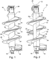
- FIGS. 1 or 2 are shown. Due to the largely same structure of the two augers 10 is a description directly with reference to both figures.
- the auger 10 has a tubular central shaft 14, which is arranged coaxially to a vertical axis 12.
- the term "vertical” refers to the usual arrangement of the auger 10 in operation, and in certain cases also deviations of the screw arrangement occur by a few degrees different from the vertical and are included.
- a pilot 16 is arranged as a centering tip.
- a connecting device 28 is arranged, which is designed in particular for connection to a Kelly bar.
- a removal device 18 which is constructed of a plurality of Abtragszähnen.
- soil material is removed during operation of the auger 10 and crushed.
- the abraded soil material is conveyed by the ablation device 18 in a rearward area onto a drill spiral 20 which helically extends around the tubular central shaft 18 to an upper end region.
- the drilling helix 20 is constructed in the illustrated schematic embodiment of three drill coils 24, each covering about a full circle.
- the drill bit 20 has a base coil 21, which has a perpendicular to the vertical axis 12 perpendicular or horizontal course in a conventional manner in vertical section.
- a first discharge element 30a is applied on the upper side and a second, smaller discharge element 30b is applied on its lower side.
- the diverting elements 30a, 30b are also helical, but face each other the vertical axis 12 a sharp discharge angle 38.
- the discharge angle 38 is the respective smaller angle, which is spanned by the vertical axis 12 and a discharge surface 32 of the discharge element 30 in vertical section.
- the discharge element 30b widens in the axial direction of the drill spiral 20.
- the obliquely arranged discharge elements 30a, 30b form an approximately wedge-shaped intermediate space 22 between the individual drill coils 24 which extends radially outwardly extended.
- a sliding coating by which the static friction is reduced.
- a sliding coating by which the static friction is reduced.
- a removal device of which in Fig. 2 only nozzle openings 42 are shown on the central shaft 14.
- a lubricating fluid such as a vegetable oil, can be sprayed onto the drilling helix 20 via a feed line (not shown) in the interior of the center shaft 14. The application can take place before and / or during drilling or emptying.
- the auger 10 is faster again after a drilling operation for a further drilling operation available. This can increase the machine usage. To shake off the soil material can also be rotated at a slower speed, which damage to the device can be avoided.
Landscapes
- Engineering & Computer Science (AREA)
- Life Sciences & Earth Sciences (AREA)
- Geology (AREA)
- Mining & Mineral Resources (AREA)
- Mechanical Engineering (AREA)
- Physics & Mathematics (AREA)
- Environmental & Geological Engineering (AREA)
- Fluid Mechanics (AREA)
- General Life Sciences & Earth Sciences (AREA)
- Geochemistry & Mineralogy (AREA)
- Earth Drilling (AREA)
Claims (12)
- Tarière de forage terrestre avec une tige centrale (14) tubulaire et coaxiale par rapport à un axe vertical (12) et avec au moins une hélice de forage (20) composée d'une tôle, l'hélice de forage (20) s'étendant en forme d'hélice autour de la tige centrale (14) et étant fixée à celle-ci, et un élément de déviation (30) servant à former une surface de déviation (32) étant disposé sur l'hélice de forage (20) avec un profil de section transversale rectangulaire,
la surface de déviation (32) étant inclinée radialement vers l'extérieur au niveau de l'hélice de forage (20) pour dévier de manière radiale du matériau de sol retiré et présente, dans une coupe verticale, un angle de déviation (38) différent de 90° par rapport à l'axe vertical (12),
caractérisée
en ce que la surface de déviation (32) est disposée dans une zone partielle radialement intérieure de l'hélice de forage (20). - Tarière selon la revendication 1,
caractérisée
en ce que l'hélice de forage est soudée à la tige centrale (14). - Tarière selon la revendication 1 ou 2,
caractérisée
en ce qu'un espace intermédiaire (22), qui est délimité entre deux spires (24) axialement adjacentes de l'hélice de forage (20), s'élargit depuis l'axe vertical (12) vers l'extérieur radialement. - Tarière selon la revendication 3,
caractérisée
en ce que l'élément de déviation (30) est formé à partir d'une tôle. - Tarière selon l'une des revendications 1 à 4,
caractérisée
en ce que la surface de déviation (32) est disposée sur un côté supérieur, un côté inférieur ou le côté supérieur et le côté inférieur de l'hélice de forage (32). - Tarière selon l'une des revendications 1 à 5,
caractérisée
en ce que la surface de déviation (32) est disposée seulement dans une zone partielle axiale de l'hélice de forage (20). - Tarière selon l'une des revendications 1 à 6,
caractérisée
en ce que la surface de déviation (32) est réalisée dans la section transversale de manière linéaire ou en forme d'arc. - Tarière selon l'une des revendications 1 à 7,
caractérisée
en ce que l'angle de déviation (38) varie dans le profil axial de l'hélice de forage (20). - Tarière selon l'une des revendications 1 à 6,
caractérisée
en ce que l'hélice de forage (20) avec la surface de déviation (32) est pourvue d'un revêtement de glissement. - Tarière selon la revendication 9,
caractérisée
en ce qu'est prévu un système d'application, avec lequel le revêtement de glissement peut être appliqué sur l'hélice de forage (20). - Tarière selon la revendication 10,
caractérisée
en ce que le système d'application présente au moins une ouverture de buse (42), laquelle est reliée à un conduit d'amenée. - Appareil de forage servant au forage terrestre,
avec un mât sensiblement vertical, le long duquel une tarière (10) peut être déplacée et entraînée en rotation,
caractérisé
en ce qu'une tarière (10) selon l'une des revendications 1 à 11 est prévue.
Priority Applications (2)
| Application Number | Priority Date | Filing Date | Title |
|---|---|---|---|
| EP13193903.5A EP2876246B1 (fr) | 2013-11-21 | 2013-11-21 | Tarière pour le forage terrestre |
| CN201410670151.8A CN104653110B (zh) | 2013-11-21 | 2014-11-21 | 用于土地钻孔的螺旋钻 |
Applications Claiming Priority (1)
| Application Number | Priority Date | Filing Date | Title |
|---|---|---|---|
| EP13193903.5A EP2876246B1 (fr) | 2013-11-21 | 2013-11-21 | Tarière pour le forage terrestre |
Publications (2)
| Publication Number | Publication Date |
|---|---|
| EP2876246A1 EP2876246A1 (fr) | 2015-05-27 |
| EP2876246B1 true EP2876246B1 (fr) | 2019-05-01 |
Family
ID=49641601
Family Applications (1)
| Application Number | Title | Priority Date | Filing Date |
|---|---|---|---|
| EP13193903.5A Active EP2876246B1 (fr) | 2013-11-21 | 2013-11-21 | Tarière pour le forage terrestre |
Country Status (2)
| Country | Link |
|---|---|
| EP (1) | EP2876246B1 (fr) |
| CN (1) | CN104653110B (fr) |
Families Citing this family (5)
| Publication number | Priority date | Publication date | Assignee | Title |
|---|---|---|---|---|
| EP3361040B1 (fr) * | 2017-02-13 | 2019-11-27 | BAUER Maschinen GmbH | Outil de traitement de sol et procédé de production d'un trou dans le sol |
| CN106869775B (zh) * | 2017-03-08 | 2018-11-27 | 杭州富阳飞尚装饰工程有限公司 | 一种市政桩基工程用的弧形地桩螺旋钻 |
| EP3581756A1 (fr) * | 2018-06-11 | 2019-12-18 | HILTI Aktiengesellschaft | Dispositif de forage |
| CN111980593B (zh) * | 2020-09-10 | 2022-05-17 | 贵州财经大学 | 一种石油开采用钻井装置 |
| CN113250610B (zh) * | 2021-06-07 | 2022-11-08 | 山东科技大学 | 一种螺旋推进式地下勘探小车 |
Citations (1)
| Publication number | Priority date | Publication date | Assignee | Title |
|---|---|---|---|---|
| US2981403A (en) * | 1957-04-15 | 1961-04-25 | Joy Mfg Co | Conveying apparatus |
Family Cites Families (8)
| Publication number | Priority date | Publication date | Assignee | Title |
|---|---|---|---|---|
| DE2059232B1 (de) * | 1970-12-02 | 1972-03-09 | Werkzeugbau Gmbh | Gesteinsbohrer |
| DE3446900C2 (de) | 1984-12-21 | 1986-10-23 | Karl Bauer Spezialtiefbau GmbH & Co KG, 8898 Schrobenhausen | Verfahren und Vorrichtung zum Reinigen der Wendel eines Schneckenbohrers |
| DE8437600U1 (de) | 1984-12-21 | 1988-09-08 | Bauer Spezialtiefbau GmbH, 8898 Schrobenhausen | Vorrichtung zum Austragen von Bohrgut aus der Bohrschnecke eines Schneckenbohrgerätes für Erdbohrungen |
| CN1078519A (zh) * | 1992-05-12 | 1993-11-17 | 王英权 | 钻孔注浆成桩法及钻具旋喷装置 |
| GB9719254D0 (en) * | 1997-09-11 | 1997-11-12 | Limited | Earthworking equipment |
| US6321861B1 (en) * | 1999-06-15 | 2001-11-27 | Henry S. Leichter | Auger |
| ITUD20020117A1 (it) | 2002-05-30 | 2003-12-01 | Casagrande Spa | Dispositivo di pulizia per utensili ad elica e procedimento di pulizia di un utensile ad elica adottante tale dispositivo |
| EP1895090B1 (fr) * | 2006-08-23 | 2008-10-15 | BAUER Maschinen GmbH | Procédé et dispositif de réalisation d'un trou de forage dans le sol |
-
2013
- 2013-11-21 EP EP13193903.5A patent/EP2876246B1/fr active Active
-
2014
- 2014-11-21 CN CN201410670151.8A patent/CN104653110B/zh active Active
Patent Citations (1)
| Publication number | Priority date | Publication date | Assignee | Title |
|---|---|---|---|---|
| US2981403A (en) * | 1957-04-15 | 1961-04-25 | Joy Mfg Co | Conveying apparatus |
Also Published As
| Publication number | Publication date |
|---|---|
| CN104653110A (zh) | 2015-05-27 |
| EP2876246A1 (fr) | 2015-05-27 |
| CN104653110B (zh) | 2017-06-20 |
Similar Documents
| Publication | Publication Date | Title |
|---|---|---|
| EP1895090B1 (fr) | Procédé et dispositif de réalisation d'un trou de forage dans le sol | |
| EP2876246B1 (fr) | Tarière pour le forage terrestre | |
| EP2133507B1 (fr) | Dispositif et procédé de forage | |
| EP0855489B1 (fr) | Perçoir qui déplace la terre | |
| EP2863003A2 (fr) | Outil et dispositif d'agrandissement d'un passage existant dans le sol | |
| DE69002583T2 (de) | Reiniger für Schneckenbohrer. | |
| EP2011958B1 (fr) | Tarière | |
| EP1491716A2 (fr) | Méthode de forage et outil de forage humide | |
| DE3446902A1 (de) | Vorrichtung zum austragen von bohrgut aus der bohrschnecke eines schneckenbohrgeraetes fuer erdbohrungen | |
| DE69103007T2 (de) | Doppelkernrohr für abgelenkte bohrungen. | |
| WO1984002555A1 (fr) | Installation pour pratiquer des trous de forage dans les parois laterales de chambres d'exploitation souterraines de largeur limitee | |
| DE202015102848U1 (de) | Kernbohrwerkzeug zum Gesteinsbohren | |
| DE4107834A1 (de) | Verdraengerbohrer sowie antriebseinrichtung fuer einen solchen | |
| EP0837190A2 (fr) | Dispositif et procédé pour la réalisation controlée de pieux et parois moulées dans le sol | |
| EP2666911B1 (fr) | Procédé de fabrication d'une paroi en mortier fixée dans le sol | |
| DE8437600U1 (de) | Vorrichtung zum Austragen von Bohrgut aus der Bohrschnecke eines Schneckenbohrgerätes für Erdbohrungen | |
| EP1905945A1 (fr) | Tarière pour excaver un puits dans le sol | |
| DE2657751B1 (de) | UEberlagerungsbohrgestaenge | |
| EP3361040B1 (fr) | Outil de traitement de sol et procédé de production d'un trou dans le sol | |
| DE19651586C2 (de) | Bohrvorrichtung für Teilverdrängungspfähle | |
| EP1580323B1 (fr) | Tarière creuse pour la réalisation de pieux moulés dans le sol | |
| EP3190257B1 (fr) | Dispositif de forage et procede de fabrication d'un pieu fore dans le sol | |
| EP3862528A1 (fr) | Appareil de forage d'un trou et procédé de production d'un trou | |
| DE102004062129B4 (de) | Vortriebsmaschine zum horizontalen Vortrieb unterirdischer Leitungstunnel | |
| DE2845316C2 (de) | Vorrichtung zur Herstellung eines Bohrlochs für einen in das Bohrloch einpreßbaren Mantelrohrstrang |
Legal Events
| Date | Code | Title | Description |
|---|---|---|---|
| PUAI | Public reference made under article 153(3) epc to a published international application that has entered the european phase |
Free format text: ORIGINAL CODE: 0009012 |
|
| 17P | Request for examination filed |
Effective date: 20131121 |
|
| AK | Designated contracting states |
Kind code of ref document: A1 Designated state(s): AL AT BE BG CH CY CZ DE DK EE ES FI FR GB GR HR HU IE IS IT LI LT LU LV MC MK MT NL NO PL PT RO RS SE SI SK SM TR |
|
| AX | Request for extension of the european patent |
Extension state: BA ME |
|
| R17P | Request for examination filed (corrected) |
Effective date: 20150708 |
|
| RBV | Designated contracting states (corrected) |
Designated state(s): AL AT BE BG CH CY CZ DE DK EE ES FI FR GB GR HR HU IE IS IT LI LT LU LV MC MK MT NL NO PL PT RO RS SE SI SK SM TR |
|
| STAA | Information on the status of an ep patent application or granted ep patent |
Free format text: STATUS: EXAMINATION IS IN PROGRESS |
|
| 17Q | First examination report despatched |
Effective date: 20170824 |
|
| GRAP | Despatch of communication of intention to grant a patent |
Free format text: ORIGINAL CODE: EPIDOSNIGR1 |
|
| STAA | Information on the status of an ep patent application or granted ep patent |
Free format text: STATUS: GRANT OF PATENT IS INTENDED |
|
| INTG | Intention to grant announced |
Effective date: 20181205 |
|
| GRAS | Grant fee paid |
Free format text: ORIGINAL CODE: EPIDOSNIGR3 |
|
| GRAA | (expected) grant |
Free format text: ORIGINAL CODE: 0009210 |
|
| STAA | Information on the status of an ep patent application or granted ep patent |
Free format text: STATUS: THE PATENT HAS BEEN GRANTED |
|
| AK | Designated contracting states |
Kind code of ref document: B1 Designated state(s): AL AT BE BG CH CY CZ DE DK EE ES FI FR GB GR HR HU IE IS IT LI LT LU LV MC MK MT NL NO PL PT RO RS SE SI SK SM TR |
|
| REG | Reference to a national code |
Ref country code: GB Ref legal event code: FG4D Free format text: NOT ENGLISH |
|
| REG | Reference to a national code |
Ref country code: CH Ref legal event code: EP Ref country code: AT Ref legal event code: REF Ref document number: 1127116 Country of ref document: AT Kind code of ref document: T Effective date: 20190515 |
|
| REG | Reference to a national code |
Ref country code: DE Ref legal event code: R096 Ref document number: 502013012741 Country of ref document: DE |
|
| REG | Reference to a national code |
Ref country code: IE Ref legal event code: FG4D Free format text: LANGUAGE OF EP DOCUMENT: GERMAN |
|
| REG | Reference to a national code |
Ref country code: NL Ref legal event code: MP Effective date: 20190501 |
|
| REG | Reference to a national code |
Ref country code: LT Ref legal event code: MG4D |
|
| PG25 | Lapsed in a contracting state [announced via postgrant information from national office to epo] |
Ref country code: NO Free format text: LAPSE BECAUSE OF FAILURE TO SUBMIT A TRANSLATION OF THE DESCRIPTION OR TO PAY THE FEE WITHIN THE PRESCRIBED TIME-LIMIT Effective date: 20190801 Ref country code: HR Free format text: LAPSE BECAUSE OF FAILURE TO SUBMIT A TRANSLATION OF THE DESCRIPTION OR TO PAY THE FEE WITHIN THE PRESCRIBED TIME-LIMIT Effective date: 20190501 Ref country code: NL Free format text: LAPSE BECAUSE OF FAILURE TO SUBMIT A TRANSLATION OF THE DESCRIPTION OR TO PAY THE FEE WITHIN THE PRESCRIBED TIME-LIMIT Effective date: 20190501 Ref country code: LT Free format text: LAPSE BECAUSE OF FAILURE TO SUBMIT A TRANSLATION OF THE DESCRIPTION OR TO PAY THE FEE WITHIN THE PRESCRIBED TIME-LIMIT Effective date: 20190501 Ref country code: ES Free format text: LAPSE BECAUSE OF FAILURE TO SUBMIT A TRANSLATION OF THE DESCRIPTION OR TO PAY THE FEE WITHIN THE PRESCRIBED TIME-LIMIT Effective date: 20190501 Ref country code: AL Free format text: LAPSE BECAUSE OF FAILURE TO SUBMIT A TRANSLATION OF THE DESCRIPTION OR TO PAY THE FEE WITHIN THE PRESCRIBED TIME-LIMIT Effective date: 20190501 Ref country code: PT Free format text: LAPSE BECAUSE OF FAILURE TO SUBMIT A TRANSLATION OF THE DESCRIPTION OR TO PAY THE FEE WITHIN THE PRESCRIBED TIME-LIMIT Effective date: 20190901 Ref country code: SE Free format text: LAPSE BECAUSE OF FAILURE TO SUBMIT A TRANSLATION OF THE DESCRIPTION OR TO PAY THE FEE WITHIN THE PRESCRIBED TIME-LIMIT Effective date: 20190501 Ref country code: FI Free format text: LAPSE BECAUSE OF FAILURE TO SUBMIT A TRANSLATION OF THE DESCRIPTION OR TO PAY THE FEE WITHIN THE PRESCRIBED TIME-LIMIT Effective date: 20190501 |
|
| PG25 | Lapsed in a contracting state [announced via postgrant information from national office to epo] |
Ref country code: BG Free format text: LAPSE BECAUSE OF FAILURE TO SUBMIT A TRANSLATION OF THE DESCRIPTION OR TO PAY THE FEE WITHIN THE PRESCRIBED TIME-LIMIT Effective date: 20190801 Ref country code: GR Free format text: LAPSE BECAUSE OF FAILURE TO SUBMIT A TRANSLATION OF THE DESCRIPTION OR TO PAY THE FEE WITHIN THE PRESCRIBED TIME-LIMIT Effective date: 20190802 Ref country code: LV Free format text: LAPSE BECAUSE OF FAILURE TO SUBMIT A TRANSLATION OF THE DESCRIPTION OR TO PAY THE FEE WITHIN THE PRESCRIBED TIME-LIMIT Effective date: 20190501 Ref country code: RS Free format text: LAPSE BECAUSE OF FAILURE TO SUBMIT A TRANSLATION OF THE DESCRIPTION OR TO PAY THE FEE WITHIN THE PRESCRIBED TIME-LIMIT Effective date: 20190501 |
|
| PG25 | Lapsed in a contracting state [announced via postgrant information from national office to epo] |
Ref country code: IS Free format text: LAPSE BECAUSE OF FAILURE TO SUBMIT A TRANSLATION OF THE DESCRIPTION OR TO PAY THE FEE WITHIN THE PRESCRIBED TIME-LIMIT Effective date: 20190901 |
|
| PG25 | Lapsed in a contracting state [announced via postgrant information from national office to epo] |
Ref country code: RO Free format text: LAPSE BECAUSE OF FAILURE TO SUBMIT A TRANSLATION OF THE DESCRIPTION OR TO PAY THE FEE WITHIN THE PRESCRIBED TIME-LIMIT Effective date: 20190501 Ref country code: SK Free format text: LAPSE BECAUSE OF FAILURE TO SUBMIT A TRANSLATION OF THE DESCRIPTION OR TO PAY THE FEE WITHIN THE PRESCRIBED TIME-LIMIT Effective date: 20190501 Ref country code: CZ Free format text: LAPSE BECAUSE OF FAILURE TO SUBMIT A TRANSLATION OF THE DESCRIPTION OR TO PAY THE FEE WITHIN THE PRESCRIBED TIME-LIMIT Effective date: 20190501 Ref country code: DK Free format text: LAPSE BECAUSE OF FAILURE TO SUBMIT A TRANSLATION OF THE DESCRIPTION OR TO PAY THE FEE WITHIN THE PRESCRIBED TIME-LIMIT Effective date: 20190501 Ref country code: EE Free format text: LAPSE BECAUSE OF FAILURE TO SUBMIT A TRANSLATION OF THE DESCRIPTION OR TO PAY THE FEE WITHIN THE PRESCRIBED TIME-LIMIT Effective date: 20190501 |
|
| REG | Reference to a national code |
Ref country code: DE Ref legal event code: R097 Ref document number: 502013012741 Country of ref document: DE |
|
| PG25 | Lapsed in a contracting state [announced via postgrant information from national office to epo] |
Ref country code: SM Free format text: LAPSE BECAUSE OF FAILURE TO SUBMIT A TRANSLATION OF THE DESCRIPTION OR TO PAY THE FEE WITHIN THE PRESCRIBED TIME-LIMIT Effective date: 20190501 |
|
| PLBE | No opposition filed within time limit |
Free format text: ORIGINAL CODE: 0009261 |
|
| STAA | Information on the status of an ep patent application or granted ep patent |
Free format text: STATUS: NO OPPOSITION FILED WITHIN TIME LIMIT |
|
| PG25 | Lapsed in a contracting state [announced via postgrant information from national office to epo] |
Ref country code: TR Free format text: LAPSE BECAUSE OF FAILURE TO SUBMIT A TRANSLATION OF THE DESCRIPTION OR TO PAY THE FEE WITHIN THE PRESCRIBED TIME-LIMIT Effective date: 20190501 |
|
| 26N | No opposition filed |
Effective date: 20200204 |
|
| PG25 | Lapsed in a contracting state [announced via postgrant information from national office to epo] |
Ref country code: PL Free format text: LAPSE BECAUSE OF FAILURE TO SUBMIT A TRANSLATION OF THE DESCRIPTION OR TO PAY THE FEE WITHIN THE PRESCRIBED TIME-LIMIT Effective date: 20190501 |
|
| PG25 | Lapsed in a contracting state [announced via postgrant information from national office to epo] |
Ref country code: SI Free format text: LAPSE BECAUSE OF FAILURE TO SUBMIT A TRANSLATION OF THE DESCRIPTION OR TO PAY THE FEE WITHIN THE PRESCRIBED TIME-LIMIT Effective date: 20190501 |
|
| REG | Reference to a national code |
Ref country code: CH Ref legal event code: PL |
|
| PG25 | Lapsed in a contracting state [announced via postgrant information from national office to epo] |
Ref country code: MC Free format text: LAPSE BECAUSE OF FAILURE TO SUBMIT A TRANSLATION OF THE DESCRIPTION OR TO PAY THE FEE WITHIN THE PRESCRIBED TIME-LIMIT Effective date: 20190501 Ref country code: CH Free format text: LAPSE BECAUSE OF NON-PAYMENT OF DUE FEES Effective date: 20191130 Ref country code: LI Free format text: LAPSE BECAUSE OF NON-PAYMENT OF DUE FEES Effective date: 20191130 Ref country code: LU Free format text: LAPSE BECAUSE OF NON-PAYMENT OF DUE FEES Effective date: 20191121 |
|
| REG | Reference to a national code |
Ref country code: BE Ref legal event code: MM Effective date: 20191130 |
|
| PG25 | Lapsed in a contracting state [announced via postgrant information from national office to epo] |
Ref country code: FR Free format text: LAPSE BECAUSE OF NON-PAYMENT OF DUE FEES Effective date: 20191130 Ref country code: IE Free format text: LAPSE BECAUSE OF NON-PAYMENT OF DUE FEES Effective date: 20191121 |
|
| PG25 | Lapsed in a contracting state [announced via postgrant information from national office to epo] |
Ref country code: BE Free format text: LAPSE BECAUSE OF NON-PAYMENT OF DUE FEES Effective date: 20191130 |
|
| REG | Reference to a national code |
Ref country code: AT Ref legal event code: MM01 Ref document number: 1127116 Country of ref document: AT Kind code of ref document: T Effective date: 20191121 |
|
| PG25 | Lapsed in a contracting state [announced via postgrant information from national office to epo] |
Ref country code: AT Free format text: LAPSE BECAUSE OF NON-PAYMENT OF DUE FEES Effective date: 20191121 |
|
| PG25 | Lapsed in a contracting state [announced via postgrant information from national office to epo] |
Ref country code: CY Free format text: LAPSE BECAUSE OF FAILURE TO SUBMIT A TRANSLATION OF THE DESCRIPTION OR TO PAY THE FEE WITHIN THE PRESCRIBED TIME-LIMIT Effective date: 20190501 |
|
| PG25 | Lapsed in a contracting state [announced via postgrant information from national office to epo] |
Ref country code: MT Free format text: LAPSE BECAUSE OF FAILURE TO SUBMIT A TRANSLATION OF THE DESCRIPTION OR TO PAY THE FEE WITHIN THE PRESCRIBED TIME-LIMIT Effective date: 20190501 Ref country code: HU Free format text: LAPSE BECAUSE OF FAILURE TO SUBMIT A TRANSLATION OF THE DESCRIPTION OR TO PAY THE FEE WITHIN THE PRESCRIBED TIME-LIMIT; INVALID AB INITIO Effective date: 20131121 |
|
| PG25 | Lapsed in a contracting state [announced via postgrant information from national office to epo] |
Ref country code: MK Free format text: LAPSE BECAUSE OF FAILURE TO SUBMIT A TRANSLATION OF THE DESCRIPTION OR TO PAY THE FEE WITHIN THE PRESCRIBED TIME-LIMIT Effective date: 20190501 |
|
| PGFP | Annual fee paid to national office [announced via postgrant information from national office to epo] |
Ref country code: DE Payment date: 20241121 Year of fee payment: 12 |
|
| PGFP | Annual fee paid to national office [announced via postgrant information from national office to epo] |
Ref country code: GB Payment date: 20241125 Year of fee payment: 12 |
|
| PGFP | Annual fee paid to national office [announced via postgrant information from national office to epo] |
Ref country code: IT Payment date: 20241108 Year of fee payment: 12 |