EP1580323B1 - Tarière creuse pour la réalisation de pieux moulés dans le sol - Google Patents
Tarière creuse pour la réalisation de pieux moulés dans le sol Download PDFInfo
- Publication number
- EP1580323B1 EP1580323B1 EP04007474A EP04007474A EP1580323B1 EP 1580323 B1 EP1580323 B1 EP 1580323B1 EP 04007474 A EP04007474 A EP 04007474A EP 04007474 A EP04007474 A EP 04007474A EP 1580323 B1 EP1580323 B1 EP 1580323B1
- Authority
- EP
- European Patent Office
- Prior art keywords
- auger
- drill pipe
- soil
- pipe
- helical turn
- Prior art date
- Legal status (The legal status is an assumption and is not a legal conclusion. Google has not performed a legal analysis and makes no representation as to the accuracy of the status listed.)
- Expired - Lifetime
Links
Images



Classifications
-
- E—FIXED CONSTRUCTIONS
- E21—EARTH OR ROCK DRILLING; MINING
- E21B—EARTH OR ROCK DRILLING; OBTAINING OIL, GAS, WATER, SOLUBLE OR MELTABLE MATERIALS OR A SLURRY OF MINERALS FROM WELLS
- E21B10/00—Drill bits
- E21B10/44—Bits with helical conveying portion, e.g. screw type bits; Augers with leading portion or with detachable parts
-
- E—FIXED CONSTRUCTIONS
- E02—HYDRAULIC ENGINEERING; FOUNDATIONS; SOIL SHIFTING
- E02D—FOUNDATIONS; EXCAVATIONS; EMBANKMENTS; UNDERGROUND OR UNDERWATER STRUCTURES
- E02D5/00—Bulkheads, piles, or other structural elements specially adapted to foundation engineering
- E02D5/22—Piles
- E02D5/34—Concrete or concrete-like piles cast in position ; Apparatus for making same
- E02D5/36—Concrete or concrete-like piles cast in position ; Apparatus for making same making without use of mouldpipes or other moulds
Definitions
- the invention relates to a drilling auger with a drill pipe to which at least one helix is arranged along the drill pipe while forming at least one helical turn, according to the preamble of claim 1.
- the invention further relates to a method for creating a foundation column in the ground.
- EP 0 732 452 B1 discloses a method for creating a foundation column in the ground, in which a drilling screw, which passes through a filling hopper filled with filling material, is pressed in to form a cavity. By means of screw conveyor by turning and simultaneous axial movement of the auger this cavity is filled with the bulk material.
- Augers are known from EP 517 329 B1 and EP 0 974 729 B1, each with a helical turn. These known augers have closure devices with which a cross section of the respective auger can be closed on the bottom side below the helical turn.
- the object of the invention is to provide a drilling auger and a method for creating a foundation element in the ground with a auger, which allow the production of particularly high quality foundation columns in a particularly reliable and robust design of the auger.
- a drilling screw according to the invention is characterized in that a blocking device for blocking the turning course is provided on the drill pipe.
- a first basic idea of the invention can be seen in a blocking device, with which a material flow which is largely unhindered in an unlocked state of the blocking device is selectively blocked in the helical turn, i. as far as possible prevented or at least obstructed.
- a material transport along the auger in different stages of the process can be selectively influenced. This additional possibility of process control enables the production of high-quality foundation elements.
- the locking device is not designed for cross-section closing a drill cross section below the helical gear, but to lock the helical gear itself.
- the helical gear can thus be divided into at least two sections, in which sections even a largely undisturbed material transport is possible, whereas a material transport between the two sections is blocked.
- a targeted arrangement and operation of the locking device to lock the helical gear at a predetermined position along the helical gear material transport along the auger can be influenced particularly precise and locally determined, which allows the production of foundation columns of very high quality in different soils.
- the locking device for locking in the helical turn this can be arranged in particular spaced from a drill bit of the drill pipe and / or from a bottom-side cutting edge of the helical turn.
- the locking device is in particular not exposed to the comparatively high degree of wear due to the undrilled soil material pending on the bottom of the auger, which increases the reliability and robustness of the device according to the invention.
- the at least one helix is suitably designed helically according to the invention.
- the spiral passage can be understood to mean the space which is formed between the at least one helix, the drill pipe and a cylindrical envelope of the at least one helix.
- a particularly suitable for the production of foundation pillars embodiment of the auger according to the invention is characterized in that the locking device is designed to lock the helical turn in a lower portion of the helix.
- the locking device is designed to lock the helical turn in a lower portion of the helix.
- Under a lower region in which the helical turn is blocked can be understood in particular such a range, which arranged a maximum of five, preferably a maximum of two, in particular a maximum of one revolution of the helix around the drill pipe from a bottom end of the helix, in particular from its cutting edge is.
- a particularly effective locking device can be provided according to the invention in that the locking device has a closure element which is adjustable from an opening position on the drill pipe in a locking position in the helical gear.
- the closure element In the opening position on the drill pipe, the closure element can abut in particular on the drill pipe and / or be sunk at least partially in the interior of the drill pipe.
- the preferably rigidly formed closure element In the blocking position, the preferably rigidly formed closure element protrudes suitably out of the drill pipe.
- a cross section of the helical gear can be partially or completely blocked by the closure element in the blocking position.
- a particularly advantageous embodiment of the invention is characterized in that the closure element for adjusting in the locking position on the drill pipe is at least approximately movable in a radial direction of the drill pipe.
- the closure element may in particular be formed as a plate which is movable from the interior of the drill pipe into the helical gear and which suitably has an outer circumference which corresponds approximately to a cross section of the helical gear.
- a wedge slide mechanism may preferably be provided.
- a further advantageous embodiment of the invention is characterized in that the closure element for adjusting in the locking position about a preferably radially to the drill pipe extending pivot axis is pivotable.
- the closure element is also formed plate-like.
- a particularly reliable auger is inventively characterized in that the drill pipe is formed axially in several parts with at least two preferably helically wound pipe parts which are axially displaceable against each other to lock the helical gear. If the pipe parts have all helices, a relative displacement of the helixes against each other during axial displacement of the pipe parts to lock the helical gear can already be sufficient. Thus, it may be due to the displacement of the individual coils of the pipe parts against each other to discontinuities in the helical turn, in which the individual coils do not form a continuous total helix more. In particular, edges of the helixes can at least partially obstruct helical turns of adjacent tube parts.
- a structurally particularly simple locking device is provided according to the invention. If a locking device with at least a closure element is used, alternatively or additionally, an adjusting mechanism may be provided which converts the displacement of the pipe parts against each other in an adjustment movement of the closure element from the open position to the locked position and vice versa.
- the locking device is formed so that the helical gear is locked when pushed together pipe parts and is unlocked when pushed apart pipe parts is particularly advantageous.
- the tube parts are shifted depending on the load, ie. that the pipe parts are pushed together during advancement of the drill pipe in the ground due to the force acting on the drill pipe axial force.
- a restoring device for example a return spring, can be provided, which pushes the tube parts apart again as the ballast or axial force decreases.
- a sliding frame drive can be provided.
- a particularly useful development of the invention is characterized in that a first pipe part has a drill bit and that the first pipe part is axially displaceable with respect to a second pipe part which has a shank of the drill pipe.
- the first tube part is configured axially shorter than the second tube part.
- the helix of the first pipe part suitably has a maximum of five, in particular a maximum of two revolutions around the drill pipe.
- the first pipe part may also be referred to as a screw start.
- at least one through-opening for introducing a liquid into the soil is provided on the drill pipe.
- the at least one passage opening in the region of the drill bit, in particular on the bottom side, the first tube part is arranged.
- the helical turn of the invention can also be referred to as helical interspace.
- the invention consists in a method for creating a foundation column in the ground, in which a drilling auger with a drill pipe, which is occupied by the formation of at least one helical turn with at least one coil, is introduced into the soil, and the auger after Reaching an end depth is rotated in a downward conveying direction while a soil additive material is conveyed into the soil with the helical drill pipe, wherein the helical gear is locked for a passage of the soil additive material.
- a downward conveying direction may, in particular, be understood as meaning a direction of rotation of the auger in which the helix of the auger conveys material into the soil, i. in which material is conveyed along the drill pipe in the direction of a drill bit of the drill pipe to be directed.
- the soil supplement material may be a soil conditioning material which may suitably solidify the soil.
- the additional soil material is a bulk material, in particular a flour or dust-like material.
- the soil additive material can also have a liquid content.
- Another basic idea of the invention can be seen in first introducing a drilling screw into the ground up to an end depth which corresponds to the depth of the foundation column to be created. At the latest after the drilling screw has reached the final depth, this is rotated in the downward conveying direction, whereby the formation of the foundation pillar additional soil material in the helical turn of the auger on the auger along the bore edge in the introduction the Bohrschnecke resulting hole is promoted.
- the invention provides that the helical gear is locked when turning the auger at least until reaching the final depth.
- a particularly advantageous development of the method according to the invention is characterized in that the helical turn is locked in a lower region of the helix.
- foundation columns with a particularly high material density along their entire length can be created.
- a lower region may, in particular, be understood as meaning such a region as has already been discussed in connection with the auger according to the invention.
- the auger is rotated during insertion into the ground in the downward conveying direction or is rotationally stationary. Under a rotation standstill is understood that the auger is not rotated. Through this advantageous process management can be largely prevented that the auger during Introducing into the soil, ie when drilling, soil material from the bore also promotes. Rather, it can be ensured that the soil material is displaced. By drilling with a rotation of the auger counter to an upward conveying direction of the auger or standstill of the auger particularly viable foundation columns can be made.
- the auger when the auger is pulled, the helical gait is unlocked and the auger is in particular further rotated in the downward conveying direction.
- unlocking the additional soil material can now be promoted along the entire spiral path to the drill bit, and there fill a cavity that arises when pulling the drill string. It is basically possible to promote the additional soil material only due to the gravitational effect at rotational halt the auger into the cavity. It is particularly advantageous, however, that the auger is rotated while pulling in the downward conveying direction.
- a liquid, especially water is passed into the ground.
- the passage opening is suitably arranged in a lower region of the drill pipe, in particular in the region of the drill bit.
- An inventive drill has a drill screw according to the invention, and a rotary drive for rotating the auger, at least in the downward conveying direction and a feed drive for axially advancing the drill pipe in the ground.
- the drill can be used in particular for carrying out the method according to the invention. In this way, as well as through the use of the auger according to the invention, the above-described advantages can be achieved with the drilling device according to the invention.
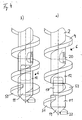
- FIGS. 1 to 5 Different embodiments of inventive augers are shown in a partially sectioned side view in Figures 1 to 5.
- the subfigure a) in the respective FIGS. 1 to 5 show the locking device in opening positions, ie in the unlocked, i. with freely continuous Wendelgang, while the subfigures b) show the respective locking device with locked Wendelgang.
- the augers shown in FIGS. 1 to 5 all have a drill pipe 2 with a drill bit 14 arranged at the bottom and at the bottom.
- a helical spiral 4 is provided on the outside of the drill pipe 2 in each case.
- a helical helix 6 is formed in each case.
- the helices 4 are each closed by a cutting edge 22.
- the drill pipes 2 have an upper, second boring part 12 with a through-opening 20, with which a liquid can be introduced from a tube arranged inside the drill pipe 2 into the floor arranged outside the drill pipe 2 is.
- the drill pipe 2 has two coils 4, 4 ', between which two helical turns 6, 6' are formed.
- the helical turn 6 is bounded on the upper side by the helix 4 'and on the underside by the helix 4.
- the helical turn 6 ' is bounded on the upper side by the helix 4 and on the underside by the helix 4'.
- the locking device has a plate-like, circumferentially rectangular closure element 30, whose longitudinal side extends approximately parallel to a longitudinal axis 3 of the drill pipe 2.
- the closure element 30 When unlocked Wendelgang 6, the closure element 30 is completely in Drilled drill pipe 2.
- the closure element 30 (as shown in FIG. 1b) is moved through a slot in the drill pipe 2 out of this.
- the closure element 30 is thereby moved in a radial direction with respect to the longitudinal axis 3 of the drill pipe 2.
- a wedge-sliding mechanism is arranged on the closure element 30.
- This wedge-sliding mechanism has a pin 33 which extends in a groove 32 of an adjusting rod 36 extending obliquely to the longitudinal axis 3.
- this adjusting rod 36 is moved up and down in the axial direction relative to the longitudinal axis 3 with respect to the drill pipe 2, wherein the wedge-sliding mechanism converts this axial movement of the adjusting rod 36 into a radial movement of the closure element 30.
- FIG. 2 Another embodiment of a drilling auger with a locking device with a plate-like closure element 30 'is shown in Fig. 2.
- the closure element 30 ' is also moved out of the drill pipe 2 in order to block the helical gear 6 in a radial direction to the longitudinal axis 3.
- no adjusting rod 36 is provided for moving the closure element 30 '. Rather, in the embodiment shown in Fig.
- the drill pipe 2 is made in two parts, with a bottom-side first pipe part 11, on which the drill bit 14 is arranged, and with a second pipe part 12 disposed above the first pipe part 11 and the second pipe part 12th are arranged in the axial direction, ie in the direction of the longitudinal axis 3 of the drill pipe 2 against each other slidably.
- a first part coil 51 and the second tube part 12 On the first tube part 11, a first part coil 51 and the second tube part 12, a second part coil 52 is arranged on the outside, wherein the two part coils 51, 52 form the coil 4.
- the first blank 11 has on its side facing away from the drill bit 14 an extension 17, which is for guiding the first pipe part 11 and the second pipe part 12 in the second Pipe part 12 protrudes.
- the first pipe part 11 is solid.
- FIG. 3 Another embodiment of a drilling auger according to the invention with a locking device is shown in Fig. 3.
- the locking device has a flap designed as a pivotable closure element 40.
- This closure element 40 can be pivoted about a pivot axis 41, which is arranged approximately radially to the longitudinal axis 3 of the drill pipe 2. While the closure element 40 is in the unlocked position completely in the interior of the drill pipe 2, this works in the locked position of a provided in the drill pipe 2 slot out of this.
- the closure element 40 can be pivoted, for example, via a not shown, arranged in the interior of the drill pipe 2 adjusting rod, which can be in communication with an adjusting drive, also not shown.
- a pivoting of the closure element 40 in analogy to the embodiment shown in FIG. 2 also be effected by moving two pipe parts against each other.
- the drill pipe 2 is formed again in two parts, in analogy to the embodiment shown in FIG. 2, with a lower, first tube part 11 and an upper, second tube part 12.
- the first tube part 11 is provided with a first part coil 51 and the second blank 12 with a second sub-coil 52. If the two tube parts 11, 12, as shown in Fig. 4a, pushed apart, so the two part coils 51, 52 continuously form the coil 4. If the two tube parts, however, as shown in Fig. 4b, pushed together, so at the transition between the first tube part 11 and the second tube part 12, a discontinuous transition between the two part coils 51, 52 given and the two part coils form no continuous overall coil 4.
- the two tube parts 11, 12 are pushed together in a feed movement of the drill pipe 2 due to the resulting axial force and this on release of the axial force by means of a not shown in Fig. 4 in the embodiment shown in FIG Resetting device pushed apart again.
- the blocking effect of the locking device of FIG. 5 is also based on an interruption of coils 4, 4 'with displacement of two pipe parts 11, 12 against each other.
- two coils 4, 4 ' is provided.
Landscapes
- Engineering & Computer Science (AREA)
- Life Sciences & Earth Sciences (AREA)
- Mining & Mineral Resources (AREA)
- Geology (AREA)
- Structural Engineering (AREA)
- General Life Sciences & Earth Sciences (AREA)
- Environmental & Geological Engineering (AREA)
- Fluid Mechanics (AREA)
- Physics & Mathematics (AREA)
- Geochemistry & Mineralogy (AREA)
- Mechanical Engineering (AREA)
- Paleontology (AREA)
- Civil Engineering (AREA)
- General Engineering & Computer Science (AREA)
- Earth Drilling (AREA)
- Investigation Of Foundation Soil And Reinforcement Of Foundation Soil By Compacting Or Drainage (AREA)
Claims (14)
- Tarière creuse avec un tube de forage (2), sur lequel est placée au moins une spire (4, 4') en formant au moins un canal (6, 6') de spire le long du tube de forage (2),
caractérisée en ce qu'un dispositif de fermeture destiné à fermer le canal (6, 6') de spire est prévu sur le tube de forage (2). - Tarière creuse selon la revendication 1, caractérisée en ce que le dispositif de fermeture destiné à fermer le canal (6, 6') de spire est réalisé dans une partie inférieure de la spire (4, 4').
- Tarière creuse selon l'une quelconque des revendications 1 ou 2, caractérisée en ce que le dispositif de fermeture comprend au moins un élément de fermeture (30, 30', 40) qui est mobile d'une position d'ouverture sur le tube de forage (2) à une position de fermeture dans le canal (6) de spire.
- Tarière creuse selon la revendication 3, caractérisée en ce que l'élément de fermeture (30, 30') est mobile dans une direction radiale du tube de forage (2) pour se placer dans la position de fermeture sur le tube de forage (2).
- Tarière creuse selon l'une quelconque des revendications 3 ou 4, caractérisée en ce que l'élément de fermeture (40) est pivotant autour d'un axe de pivotement (41) s'étendant de préférence radialement au tube de forage (2) pour se placer dans la position de fermeture.
- Tarière creuse selon l'une quelconque des revendications 1 à 5, caractérisée en ce que le tube de forage (2) est réalisé axialement en plusieurs parties avec au moins deux parties (11, 12) de tube portant de préférence la spire, qui sont mobiles axialement l'une par rapport à l'autre pour fermer le canal (6, 6') de spire.
- Tarière creuse selon la revendication 6, caractérisée- en ce qu'une première partie (11) de tube présente une pointe de forage (14) et- en ce que la première partie (11) de tube est mobile par rapport à une deuxième partie (12) de tube qui comprend une tige du tube de forage (2).
- Tarière creuse selon l'une quelconque des revendications 1 à 7, caractérisée en ce qu'au moins une ouverture de passage (20) est prévue sur le tube de forage (2) pour introduire un liquide dans le sol.
- Procédé de réalisation d'un pieu de fondation dans le sol, dans lequel- une tarière creuse, en particulier selon l'une quelconque des revendications 1 à 8, avec un tube de forage (2) qui porte au moins une spire (4, 4') en formant au moins un canal (6, 6') de spire est enfoncé dans le sol, et- après avoir atteint une profondeur finale, la tarière creuse est tournée dans un dispositif de transport vers le bas et un matériau d'apport est introduit dans le sol avec le tube de forage (2) portant la spire, le canal (6, 6') de spire étant fermé pour un passage du matériau d'apport.
- Procédé selon la revendication 9, caractérisé en ce que le canal (6, 6') de spire est fermé dans une partie inférieure de la spire (4, 4').
- Procédé selon l'une quelconque des revendications 9 ou 10, caractérisé en ce que pendant l'introduction dans le sol, la tarière creuse est tournée dans la direction de transport vers le bas ou est immobile en rotation.
- Procédé selon l'une quelconque des revendications 9 à 11, caractérisé en ce que dès l'introduction de la tarière creuse dans le sol, du matériau d'apport est introduit dans le sol avec elle, le canal (6, 6') de spire étant fermé.
- Procédé selon l'une quelconque des revendications 9 à 12, caractérisé en ce que lors d'un retrait de la tarière creuse, le canal (6, 6') de spire est ouvert et la tarière creuse est tournée, en particulier de nouveau dans la direction de transport vers le bas.
- Dispositif de forage, en particulier pour appliquer le procédé selon l'une quelconque des revendications 9 à 13, avec- une tarière creuse selon l'une quelconque des revendications 1 à 8,- un entraînement rotatif pour faire tourner la tarière creuse au moins dans la direction de transport vers le bas, et- un entraînement de progression pour faire progresser axialement le tube de forage dans le sol.
Priority Applications (4)
| Application Number | Priority Date | Filing Date | Title |
|---|---|---|---|
| EP04007474A EP1580323B1 (fr) | 2004-03-26 | 2004-03-26 | Tarière creuse pour la réalisation de pieux moulés dans le sol |
| DE502004000661T DE502004000661D1 (de) | 2004-03-26 | 2004-03-26 | Bohrschnecke und Verfahren zum Erstellen einer Gründungssäule im Boden |
| AT04007474T ATE328161T1 (de) | 2004-03-26 | 2004-03-26 | Bohrschnecke und verfahren zum erstellen einer gründungssäule im boden |
| ES04007474T ES2265613T3 (es) | 2004-03-26 | 2004-03-26 | Barrena y procedimiento para realizar un pilar de cimentacion en el terreno con dicha barrena. |
Applications Claiming Priority (1)
| Application Number | Priority Date | Filing Date | Title |
|---|---|---|---|
| EP04007474A EP1580323B1 (fr) | 2004-03-26 | 2004-03-26 | Tarière creuse pour la réalisation de pieux moulés dans le sol |
Publications (2)
| Publication Number | Publication Date |
|---|---|
| EP1580323A1 EP1580323A1 (fr) | 2005-09-28 |
| EP1580323B1 true EP1580323B1 (fr) | 2006-05-31 |
Family
ID=34854644
Family Applications (1)
| Application Number | Title | Priority Date | Filing Date |
|---|---|---|---|
| EP04007474A Expired - Lifetime EP1580323B1 (fr) | 2004-03-26 | 2004-03-26 | Tarière creuse pour la réalisation de pieux moulés dans le sol |
Country Status (4)
| Country | Link |
|---|---|
| EP (1) | EP1580323B1 (fr) |
| AT (1) | ATE328161T1 (fr) |
| DE (1) | DE502004000661D1 (fr) |
| ES (1) | ES2265613T3 (fr) |
Families Citing this family (3)
| Publication number | Priority date | Publication date | Assignee | Title |
|---|---|---|---|---|
| CN101906938B (zh) * | 2010-07-27 | 2012-08-29 | 段正利 | 钻头 |
| EP3190257B1 (fr) * | 2016-01-08 | 2018-04-25 | BAUER Spezialtiefbau GmbH | Dispositif de forage et procede de fabrication d'un pieu fore dans le sol |
| BE1027995B1 (nl) | 2020-01-16 | 2021-08-16 | Olivier Ind Nv | Grondverdringende boor en werkwijze voor het vormen van een gladde funderingspaal met een dergelijke grondverdringende boor |
Family Cites Families (6)
| Publication number | Priority date | Publication date | Assignee | Title |
|---|---|---|---|---|
| DE334894C (de) * | 1921-03-24 | Otto Schweisgut | Erdbohrer mit einer am oberen Ende der steilgaengigen Bohrschnecke angebrachten Klappe | |
| BE502529A (fr) * | ||||
| GB191421078A (en) * | 1914-10-16 | 1915-04-01 | Benjamin Hosking Trewhella | An Improvement in Ground-augers. |
| CH96148A (de) * | 1921-05-31 | 1922-09-16 | Wahrenburg Friedrich | Erdbohrer. |
| FR2677385A1 (fr) * | 1991-06-05 | 1992-12-11 | Labrue Jean Marie | Dispositif d'injection et de controile du betonnage des pieux a la tariere creuse. |
| IT1303164B1 (it) * | 1998-07-21 | 2000-10-30 | Soilmec Spa | Dispositivo di perforazione ad elica. |
-
2004
- 2004-03-26 AT AT04007474T patent/ATE328161T1/de not_active IP Right Cessation
- 2004-03-26 EP EP04007474A patent/EP1580323B1/fr not_active Expired - Lifetime
- 2004-03-26 DE DE502004000661T patent/DE502004000661D1/de not_active Expired - Fee Related
- 2004-03-26 ES ES04007474T patent/ES2265613T3/es not_active Expired - Lifetime
Also Published As
| Publication number | Publication date |
|---|---|
| DE502004000661D1 (de) | 2006-07-06 |
| ES2265613T3 (es) | 2007-02-16 |
| ATE328161T1 (de) | 2006-06-15 |
| EP1580323A1 (fr) | 2005-09-28 |
Similar Documents
| Publication | Publication Date | Title |
|---|---|---|
| EP1895090B1 (fr) | Procédé et dispositif de réalisation d'un trou de forage dans le sol | |
| EP2133507B1 (fr) | Dispositif et procédé de forage | |
| DE3617025A1 (de) | Vorgefertigter betonpfahl sowie verfahren und vorrichtung zu seinem einbringen ins erdreich | |
| EP2770156B1 (fr) | Outil de forage et procédé de forage terrestre | |
| DE3624202C2 (de) | Spiralbohrer | |
| EP2876246B1 (fr) | Tarière pour le forage terrestre | |
| EP1580323B1 (fr) | Tarière creuse pour la réalisation de pieux moulés dans le sol | |
| DE2422489C2 (de) | Erdbohrer und Verfahren zum Einsetzen von Pfählen o.dgl. | |
| EP3091173B1 (fr) | Installation de forage déstinée à produire où à élargir un forage terrestre dans la terre et procédé de commande d'un dispositif d'avance d'une telle installation de forage | |
| DE4114457C1 (fr) | ||
| EP0837190A2 (fr) | Dispositif et procédé pour la réalisation controlée de pieux et parois moulées dans le sol | |
| EP4101987B1 (fr) | Outil de forage et procédé de production d'un forage dans le sol | |
| EP2666911B1 (fr) | Procédé de fabrication d'une paroi en mortier fixée dans le sol | |
| EP3392449B1 (fr) | Dispositif de forage et procédé de forage dans le sol | |
| EP3190257B1 (fr) | Dispositif de forage et procede de fabrication d'un pieu fore dans le sol | |
| EP3456914A1 (fr) | Dispositif de forage double tête et procédé de réalisation d'un forage | |
| DE4232560C1 (de) | Schneckenbohrvorrichtung | |
| DE2657751B1 (de) | UEberlagerungsbohrgestaenge | |
| DE19651586C2 (de) | Bohrvorrichtung für Teilverdrängungspfähle | |
| DE102006023799B4 (de) | Vorrichtung zur Herstellung von Gründungselementen | |
| DE102004059632A1 (de) | Fundamenteinrichutng für stabförmige Bauteile mit mehrfach verwendbarem Werkzeug sowie Vorrichtung zum einbringen einer derartigen Fundamenteinrichtung | |
| EP4497873B1 (fr) | Dispositif et procédé de formation d'un élément de sol | |
| EP1734222B1 (fr) | Procedée pour fabriquer des pieux sur sol | |
| EP4198253B1 (fr) | Outil de forage et procédé de production d'un forage dans le sol | |
| DE10359103A1 (de) | Drehboden für Doppelkopfbohren |
Legal Events
| Date | Code | Title | Description |
|---|---|---|---|
| PUAI | Public reference made under article 153(3) epc to a published international application that has entered the european phase |
Free format text: ORIGINAL CODE: 0009012 |
|
| AK | Designated contracting states |
Kind code of ref document: A1 Designated state(s): AT BE BG CH CY CZ DE DK EE ES FI FR GB GR HU IE IT LI LU MC NL PL PT RO SE SI SK TR |
|
| AX | Request for extension of the european patent |
Extension state: AL LT LV MK |
|
| 17P | Request for examination filed |
Effective date: 20050811 |
|
| GRAP | Despatch of communication of intention to grant a patent |
Free format text: ORIGINAL CODE: EPIDOSNIGR1 |
|
| GRAS | Grant fee paid |
Free format text: ORIGINAL CODE: EPIDOSNIGR3 |
|
| GRAA | (expected) grant |
Free format text: ORIGINAL CODE: 0009210 |
|
| AK | Designated contracting states |
Kind code of ref document: B1 Designated state(s): AT BE BG CH CY CZ DE DK EE ES FI FR GB GR HU IE IT LI LU MC NL PL PT RO SE SI SK TR |
|
| AX | Request for extension of the european patent |
Extension state: AL LT LV MK |
|
| PG25 | Lapsed in a contracting state [announced via postgrant information from national office to epo] |
Ref country code: IT Free format text: LAPSE BECAUSE OF FAILURE TO SUBMIT A TRANSLATION OF THE DESCRIPTION OR TO PAY THE FEE WITHIN THE PRESCRIBED TIME-LIMIT;WARNING: LAPSES OF ITALIAN PATENTS WITH EFFECTIVE DATE BEFORE 2007 MAY HAVE OCCURRED AT ANY TIME BEFORE 2007. THE CORRECT EFFECTIVE DATE MAY BE DIFFERENT FROM THE ONE RECORDED. Effective date: 20060531 Ref country code: IE Free format text: LAPSE BECAUSE OF FAILURE TO SUBMIT A TRANSLATION OF THE DESCRIPTION OR TO PAY THE FEE WITHIN THE PRESCRIBED TIME-LIMIT Effective date: 20060531 Ref country code: FI Free format text: LAPSE BECAUSE OF FAILURE TO SUBMIT A TRANSLATION OF THE DESCRIPTION OR TO PAY THE FEE WITHIN THE PRESCRIBED TIME-LIMIT Effective date: 20060531 Ref country code: RO Free format text: LAPSE BECAUSE OF FAILURE TO SUBMIT A TRANSLATION OF THE DESCRIPTION OR TO PAY THE FEE WITHIN THE PRESCRIBED TIME-LIMIT Effective date: 20060531 Ref country code: CZ Free format text: LAPSE BECAUSE OF FAILURE TO SUBMIT A TRANSLATION OF THE DESCRIPTION OR TO PAY THE FEE WITHIN THE PRESCRIBED TIME-LIMIT Effective date: 20060531 Ref country code: SI Free format text: LAPSE BECAUSE OF FAILURE TO SUBMIT A TRANSLATION OF THE DESCRIPTION OR TO PAY THE FEE WITHIN THE PRESCRIBED TIME-LIMIT Effective date: 20060531 Ref country code: PL Free format text: LAPSE BECAUSE OF FAILURE TO SUBMIT A TRANSLATION OF THE DESCRIPTION OR TO PAY THE FEE WITHIN THE PRESCRIBED TIME-LIMIT Effective date: 20060531 Ref country code: SK Free format text: LAPSE BECAUSE OF FAILURE TO SUBMIT A TRANSLATION OF THE DESCRIPTION OR TO PAY THE FEE WITHIN THE PRESCRIBED TIME-LIMIT Effective date: 20060531 |
|
| REG | Reference to a national code |
Ref country code: GB Ref legal event code: FG4D Free format text: NOT ENGLISH Ref country code: CH Ref legal event code: EP |
|
| AKX | Designation fees paid |
Designated state(s): AT BE BG CH CY CZ DE DK EE ES FI FR GB GR HU IE IT LI LU MC NL PL PT RO SE SI SK TR |
|
| REG | Reference to a national code |
Ref country code: IE Ref legal event code: FG4D Free format text: LANGUAGE OF EP DOCUMENT: GERMAN |
|
| REF | Corresponds to: |
Ref document number: 502004000661 Country of ref document: DE Date of ref document: 20060706 Kind code of ref document: P |
|
| GBT | Gb: translation of ep patent filed (gb section 77(6)(a)/1977) |
Effective date: 20060626 |
|
| PG25 | Lapsed in a contracting state [announced via postgrant information from national office to epo] |
Ref country code: DK Free format text: LAPSE BECAUSE OF FAILURE TO SUBMIT A TRANSLATION OF THE DESCRIPTION OR TO PAY THE FEE WITHIN THE PRESCRIBED TIME-LIMIT Effective date: 20060831 |
|
| REG | Reference to a national code |
Ref country code: SE Ref legal event code: TRGR |
|
| PG25 | Lapsed in a contracting state [announced via postgrant information from national office to epo] |
Ref country code: PT Free format text: LAPSE BECAUSE OF FAILURE TO SUBMIT A TRANSLATION OF THE DESCRIPTION OR TO PAY THE FEE WITHIN THE PRESCRIBED TIME-LIMIT Effective date: 20061031 |
|
| ET | Fr: translation filed | ||
| REG | Reference to a national code |
Ref country code: ES Ref legal event code: FG2A Ref document number: 2265613 Country of ref document: ES Kind code of ref document: T3 |
|
| REG | Reference to a national code |
Ref country code: IE Ref legal event code: FD4D |
|
| PLBE | No opposition filed within time limit |
Free format text: ORIGINAL CODE: 0009261 |
|
| STAA | Information on the status of an ep patent application or granted ep patent |
Free format text: STATUS: NO OPPOSITION FILED WITHIN TIME LIMIT |
|
| 26N | No opposition filed |
Effective date: 20070301 |
|
| PG25 | Lapsed in a contracting state [announced via postgrant information from national office to epo] |
Ref country code: MC Free format text: LAPSE BECAUSE OF NON-PAYMENT OF DUE FEES Effective date: 20070331 |
|
| PG25 | Lapsed in a contracting state [announced via postgrant information from national office to epo] |
Ref country code: GR Free format text: LAPSE BECAUSE OF FAILURE TO SUBMIT A TRANSLATION OF THE DESCRIPTION OR TO PAY THE FEE WITHIN THE PRESCRIBED TIME-LIMIT Effective date: 20060901 |
|
| PGFP | Annual fee paid to national office [announced via postgrant information from national office to epo] |
Ref country code: GB Payment date: 20080328 Year of fee payment: 5 Ref country code: NL Payment date: 20080331 Year of fee payment: 5 Ref country code: SE Payment date: 20080326 Year of fee payment: 5 |
|
| PG25 | Lapsed in a contracting state [announced via postgrant information from national office to epo] |
Ref country code: AT Free format text: LAPSE BECAUSE OF NON-PAYMENT OF DUE FEES Effective date: 20070326 Ref country code: BG Free format text: LAPSE BECAUSE OF FAILURE TO SUBMIT A TRANSLATION OF THE DESCRIPTION OR TO PAY THE FEE WITHIN THE PRESCRIBED TIME-LIMIT Effective date: 20060831 |
|
| PG25 | Lapsed in a contracting state [announced via postgrant information from national office to epo] |
Ref country code: EE Free format text: LAPSE BECAUSE OF FAILURE TO SUBMIT A TRANSLATION OF THE DESCRIPTION OR TO PAY THE FEE WITHIN THE PRESCRIBED TIME-LIMIT Effective date: 20060531 |
|
| PGFP | Annual fee paid to national office [announced via postgrant information from national office to epo] |
Ref country code: ES Payment date: 20080416 Year of fee payment: 5 Ref country code: DE Payment date: 20080328 Year of fee payment: 5 |
|
| PGFP | Annual fee paid to national office [announced via postgrant information from national office to epo] |
Ref country code: IT Payment date: 20080328 Year of fee payment: 5 Ref country code: BE Payment date: 20080416 Year of fee payment: 5 |
|
| PGRI | Patent reinstated in contracting state [announced from national office to epo] |
Ref country code: IT Effective date: 20080601 |
|
| REG | Reference to a national code |
Ref country code: CH Ref legal event code: PL |
|
| PGFP | Annual fee paid to national office [announced via postgrant information from national office to epo] |
Ref country code: FR Payment date: 20080331 Year of fee payment: 5 |
|
| PG25 | Lapsed in a contracting state [announced via postgrant information from national office to epo] |
Ref country code: LI Free format text: LAPSE BECAUSE OF NON-PAYMENT OF DUE FEES Effective date: 20080331 Ref country code: CH Free format text: LAPSE BECAUSE OF NON-PAYMENT OF DUE FEES Effective date: 20080331 |
|
| PG25 | Lapsed in a contracting state [announced via postgrant information from national office to epo] |
Ref country code: LU Free format text: LAPSE BECAUSE OF NON-PAYMENT OF DUE FEES Effective date: 20070326 Ref country code: CY Free format text: LAPSE BECAUSE OF FAILURE TO SUBMIT A TRANSLATION OF THE DESCRIPTION OR TO PAY THE FEE WITHIN THE PRESCRIBED TIME-LIMIT Effective date: 20060531 |
|
| BERE | Be: lapsed |
Owner name: *BAUER MASCHINEN G.M.B.H. Effective date: 20090331 |
|
| PG25 | Lapsed in a contracting state [announced via postgrant information from national office to epo] |
Ref country code: TR Free format text: LAPSE BECAUSE OF FAILURE TO SUBMIT A TRANSLATION OF THE DESCRIPTION OR TO PAY THE FEE WITHIN THE PRESCRIBED TIME-LIMIT Effective date: 20060531 Ref country code: HU Free format text: LAPSE BECAUSE OF FAILURE TO SUBMIT A TRANSLATION OF THE DESCRIPTION OR TO PAY THE FEE WITHIN THE PRESCRIBED TIME-LIMIT Effective date: 20061201 |
|
| EUG | Se: european patent has lapsed | ||
| GBPC | Gb: european patent ceased through non-payment of renewal fee |
Effective date: 20090326 |
|
| NLV4 | Nl: lapsed or anulled due to non-payment of the annual fee |
Effective date: 20091001 |
|
| REG | Reference to a national code |
Ref country code: FR Ref legal event code: ST Effective date: 20091130 |
|
| PG25 | Lapsed in a contracting state [announced via postgrant information from national office to epo] |
Ref country code: DE Free format text: LAPSE BECAUSE OF NON-PAYMENT OF DUE FEES Effective date: 20091001 |
|
| PG25 | Lapsed in a contracting state [announced via postgrant information from national office to epo] |
Ref country code: NL Free format text: LAPSE BECAUSE OF NON-PAYMENT OF DUE FEES Effective date: 20091001 Ref country code: BE Free format text: LAPSE BECAUSE OF NON-PAYMENT OF DUE FEES Effective date: 20090331 |
|
| PG25 | Lapsed in a contracting state [announced via postgrant information from national office to epo] |
Ref country code: GB Free format text: LAPSE BECAUSE OF NON-PAYMENT OF DUE FEES Effective date: 20090326 Ref country code: FR Free format text: LAPSE BECAUSE OF NON-PAYMENT OF DUE FEES Effective date: 20091123 |
|
| REG | Reference to a national code |
Ref country code: ES Ref legal event code: FD2A Effective date: 20090327 |
|
| PG25 | Lapsed in a contracting state [announced via postgrant information from national office to epo] |
Ref country code: ES Free format text: LAPSE BECAUSE OF NON-PAYMENT OF DUE FEES Effective date: 20090327 |
|
| PG25 | Lapsed in a contracting state [announced via postgrant information from national office to epo] |
Ref country code: IT Free format text: LAPSE BECAUSE OF NON-PAYMENT OF DUE FEES Effective date: 20090326 |
|
| PG25 | Lapsed in a contracting state [announced via postgrant information from national office to epo] |
Ref country code: SE Free format text: LAPSE BECAUSE OF NON-PAYMENT OF DUE FEES Effective date: 20090327 |