EP2876322A2 - Dispositif de débrayage - Google Patents
Dispositif de débrayage Download PDFInfo
- Publication number
- EP2876322A2 EP2876322A2 EP14190887.1A EP14190887A EP2876322A2 EP 2876322 A2 EP2876322 A2 EP 2876322A2 EP 14190887 A EP14190887 A EP 14190887A EP 2876322 A2 EP2876322 A2 EP 2876322A2
- Authority
- EP
- European Patent Office
- Prior art keywords
- piston
- ramp
- lever
- release device
- bearing
- Prior art date
- Legal status (The legal status is an assumption and is not a legal conclusion. Google has not performed a legal analysis and makes no representation as to the accuracy of the status listed.)
- Withdrawn
Links
Images







Classifications
-
- F—MECHANICAL ENGINEERING; LIGHTING; HEATING; WEAPONS; BLASTING
- F16—ENGINEERING ELEMENTS AND UNITS; GENERAL MEASURES FOR PRODUCING AND MAINTAINING EFFECTIVE FUNCTIONING OF MACHINES OR INSTALLATIONS; THERMAL INSULATION IN GENERAL
- F16D—COUPLINGS FOR TRANSMITTING ROTATION; CLUTCHES; BRAKES
- F16D23/00—Details of mechanically-actuated clutches not specific for one distinct type
- F16D23/12—Mechanical clutch-actuating mechanisms arranged outside the clutch as such
- F16D23/14—Clutch-actuating sleeves or bearings; Actuating members directly connected to clutch-actuating sleeves or bearings
-
- F—MECHANICAL ENGINEERING; LIGHTING; HEATING; WEAPONS; BLASTING
- F16—ENGINEERING ELEMENTS AND UNITS; GENERAL MEASURES FOR PRODUCING AND MAINTAINING EFFECTIVE FUNCTIONING OF MACHINES OR INSTALLATIONS; THERMAL INSULATION IN GENERAL
- F16D—COUPLINGS FOR TRANSMITTING ROTATION; CLUTCHES; BRAKES
- F16D25/00—Fluid-actuated clutches
- F16D25/08—Fluid-actuated clutches with fluid-actuated member not rotating with a clutching member
- F16D25/082—Fluid-actuated clutches with fluid-actuated member not rotating with a clutching member the line of action of the fluid-actuated members co-inciding with the axis of rotation
- F16D25/083—Actuators therefor
-
- F—MECHANICAL ENGINEERING; LIGHTING; HEATING; WEAPONS; BLASTING
- F16—ENGINEERING ELEMENTS AND UNITS; GENERAL MEASURES FOR PRODUCING AND MAINTAINING EFFECTIVE FUNCTIONING OF MACHINES OR INSTALLATIONS; THERMAL INSULATION IN GENERAL
- F16D—COUPLINGS FOR TRANSMITTING ROTATION; CLUTCHES; BRAKES
- F16D23/00—Details of mechanically-actuated clutches not specific for one distinct type
- F16D23/12—Mechanical clutch-actuating mechanisms arranged outside the clutch as such
- F16D2023/123—Clutch actuation by cams, ramps or ball-screw mechanisms
-
- F—MECHANICAL ENGINEERING; LIGHTING; HEATING; WEAPONS; BLASTING
- F16—ENGINEERING ELEMENTS AND UNITS; GENERAL MEASURES FOR PRODUCING AND MAINTAINING EFFECTIVE FUNCTIONING OF MACHINES OR INSTALLATIONS; THERMAL INSULATION IN GENERAL
- F16D—COUPLINGS FOR TRANSMITTING ROTATION; CLUTCHES; BRAKES
- F16D48/00—External control of clutches
- F16D48/02—Control by fluid pressure
- F16D2048/0212—Details of pistons for primary or secondary cylinders especially adapted for fluid control
-
- F—MECHANICAL ENGINEERING; LIGHTING; HEATING; WEAPONS; BLASTING
- F16—ENGINEERING ELEMENTS AND UNITS; GENERAL MEASURES FOR PRODUCING AND MAINTAINING EFFECTIVE FUNCTIONING OF MACHINES OR INSTALLATIONS; THERMAL INSULATION IN GENERAL
- F16D—COUPLINGS FOR TRANSMITTING ROTATION; CLUTCHES; BRAKES
- F16D48/00—External control of clutches
- F16D48/02—Control by fluid pressure
- F16D2048/0227—Source of pressure producing the clutch engagement or disengagement action within a circuit; Means for initiating command action in power assisted devices
- F16D2048/0254—Double actuation, i.e. two actuation means can produce independently an engagement or disengagement of the clutch
Definitions
- the invention relates to a release device, in particular for disengaging a clutch.
- Release devices have become known in the art in various designs.
- Today disengaging devices for clutches are used, which are opened or closed by a displaceable release bearing.
- hydraulically actuated release devices or mechanically operated release devices are known.
- the device has a slave cylinder, which is connectable to a fluid line with a master cylinder or a hydraulic pump. Therefore, reference is made to the slave and encoder system, but instead of a master cylinder, a pump may always be present.
- a clutch pedal By pressing a clutch pedal, the piston of the clutch master cylinder is retracted, whereby the present in the master cylinder and in the rest of the system fluid is forced through the conduit system and thus an extension of the piston of the clutch slave cylinder is effected.
- the piston of the clutch slave cylinder thus presses with the provided in particular integrated release bearing on the plate spring of the clutch. Through this process, the clutch is disengaged or engaged or opened or closed and the power flow between the engine and transmission is thereby interrupted or produced.
- An embodiment of the invention relates to a release device with an axially displaceable release bearing, in particular for acting on an actuating element of a clutch, wherein the release bearing has a first bearing ring and a second bearing ring, wherein the first bearing ring for acting on the actuating element and the second bearing ring for axial displacement of the release bearing is acted upon by a first actuating means and by a second actuating means, wherein the two actuating means are independently controllable.
- This ensures that the release bearing of two actuating means can be actuated independently of one another, wherein an actuating means, for example, operated pedal-operated and the other actuating means is automatically actuated by means of an actuator operable.
- an actuating means for example, operated pedal-operated and the other actuating means is automatically actuated by means of an actuator operable.
- the invention accordingly relates to a hydraulic disengaging device, in particular for a manually operable manual transmission with a master cylinder, slave cylinder and hydraulic line.
- the release device comprises the slave cylinder of the system.
- the slave cylinder In order to increase the comfort is proposed to provide the slave cylinder as a first actuating means with an additional independent actuating means for automatic clutch operation. The clutch actuation can then take place in an automatic mode by means of the second actuating means.
- the first actuating means is a first piston-cylinder unit which has a cylinder in which an axially displaceable piston is received, wherein the second bearing ring can be acted upon by means of the piston of the first piston-cylinder unit.
- a hydraulic actuation of the release bearing for example by means of a foot pedal done.
- the second actuating means is a second piston-cylinder unit which has a cylinder in which an axially displaceable piston is received, wherein the second bearing ring can be acted upon by means of the piston of the second piston-cylinder unit.
- an additional or alternative actuation by means of a further actuating means can take place.
- This is preferably an automated operation, which is also controlled hydraulically.
- a hydraulic Betuschistsaktuator be provided which is fluidly connected to the second piston-cylinder unit.
- first piston-cylinder unit and / or the second piston-cylinder unit is an annular piston-cylinder unit, wherein the cylinder and the piston arranged in the cylinder are annular. Accordingly, the piston-cylinder unit can be placed around a shaft of the transmission, so that the release bearing and the actuating means can be arranged coaxially with the transmission shaft.
- first piston-cylinder unit is arranged radially inside or radially outside of the second piston-cylinder unit. So a space-saving design can be achieved.
- the second actuating means has a pivotable lever which acts on the second bearing ring.
- the lever is designed as a one-armed lever, wherein the loading area for loading the second bearing ring between a first end portion of the lever and a second end portion of the lever is arranged, the first end portion of the storage of the lever is used and the second end portion the actuation of the lever by means of an actuator is used.
- the lever is designed as a two-armed lever, wherein the loading area is arranged to act on the second bearing ring at a first end portion of the lever and a second end portion of the lever is provided, which serves to actuate the lever by means of an actuator, wherein an area between the first end portion and the second end portion of the bearing of the lever is used.
- the mounting of the lever is made on a platform which is connected to the cylinder of the first piston-cylinder unit.
- the second actuating means has a ramp arrangement with two ramp elements rotatable relative to each other, wherein in relative rotation of the ramp elements of the ramp elements in the axial direction is displaced to act on the second bearing ring.
- the ramp arrangement is formed like a ring with the two ramp elements.
- first piston-cylinder unit is arranged radially inside or radially outside the ramp arrangement.
- first ramp element and a second ramp element are provided, wherein one of the ramp elements is U-shaped in section with two spaced legs, wherein the other ramp element is arranged in the radial direction between the legs.
- first ramp element and a second ramp element are provided, wherein the ramp elements are hollow-cylindrical and are arranged one inside the other, so that they have ramps on their inner surface and outer surface, which are supported against one another.
- one of the ramp elements by means of a cable and a Seilzugaktuators is rotatable, wherein the cable rests on the outer circumference of the rope and winds around the ramp element.
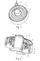
- the Fig. 1 to 4 show in various views a first embodiment of a release device according to the invention 1.
- the release device 1 has an axially displaceable release bearing 2, which serves in particular to act on an actuating element of a clutch. Due to the axial displacement of the release bearing 2, a clutch can be switched on or disengaged.
- the release bearing 2 has a first bearing ring 3 and a second bearing ring 4.
- the first bearing ring 3 is formed as a bearing outer ring and the second bearing ring 4 is formed as a bearing inner ring, between the first bearing ring 3 and the second bearing ring 4 rolling elements 5 are arranged to make the first bearing ring 3 relative to the second bearing ring 4 rotatable.
- the first bearing ring 3 serves to act on an actuating element, for example a clutch, while the second bearing ring 4 is used for the axial displacement of the release bearing 2.
- the first bearing ring 3 can be covered by a cover-like element 6, so that the actuating elements of the coupling can be acted upon by this cover-like element 6 of the first bearing ring 3.
- the second bearing ring 4 is connected to a pot-like element 7 in a positive or non-positive connection, so that when the axial displacement of the second bearing ring 4 and the cup-shaped element 7 can be axially displaced.
- the release bearing 2 is accommodated in a housing 8 within which the release bearing 2 is displaceable in the axial direction.
- the housing 8 has according to the Fig. 2 to 4 two piston-cylinder units 9, 10, which may be annular, wherein the piston-cylinder unit 9 is arranged radially inside the piston-cylinder unit 10.
- Each of the two piston-cylinder units 9, 10 has a cylinder 11, 12, a piston 13, 14 and a sealing element 15, 16.
- the piston 13 is displaced in the axial direction, the piston 13 being provided at its one cylinder-side end with the sealing element 15 and acting on the bearing inner ring 4 at its opposite end.
- the piston 13 Upon displacement of the piston 13 in the axial direction of the bearing inner ring 4 is displaced in the axial direction, so that the release bearing 2 is also displaced in the axial direction.
- the elements 2, 3 and 4 form the bearing, the element 2 is a ball or one of several balls in the camp.
- the piston 14 is displaced in the axial direction.
- the piston 14 has at one end the carrier 16 of the sealing element 12 and at its other end the piston 14 is in contact with the cup-like element 7, so that upon axial displacement of the piston 14, the cup-like element 7 is displaced axially, which in turn radially inside the second bearing ring 4 engages over and thus axially displaced the second bearing ring 3.
- the release bearing 2 can be acted upon by two independent piston-cylinder units via the pressure chambers 9 and 10, so that the release bearing 2 is displaced axially either by acting on the pressure chamber 9 or by acting on the pressure chamber 10th
- the 3 and 4 show the arrangement of the release device according to Fig. 2 in two different operating positions.
- Fig. 2 are the pistons 13, 14 and the relevant sealing elements 15, 16 in the unactuated position.
- Fig. 3 the piston 13 is displaced in the axial direction towards the release bearing 2, since a pressure medium is applied in the pressure chamber 9 Attention: Number 9 and 11 in FIG. 3 is the same pressure chamber.
- the cylinder 12 of the piston-cylinder unit 10 is unloaded, so that the piston-cylinder unit 10 does not contribute to the actuation of the release bearing.
- the Fig. 4 shows the corresponding alternative operating position in which the piston-cylinder unit 10 is pressurized medium, while the piston-cylinder unit 9 is not pressurized medium.
- the sealing element 16 is displaced in the axial direction, while the sealing element 15 is not displaced in the axial direction. Accordingly, the sealing element 16 acts on the piston 14, while the sealing element 15 does not act on the piston 13.
- the release bearing is disengaged because the piston-cylinder unit 10 is pressurized.
- the piston-cylinder units 9, 10 are ring-shaped piston-cylinder units 9, 10, which are arranged radially one inside the other.
- the piston-cylinder units 9, 10 act on the second bearing ring 4 directly or via an intermediate element, which is designed as a pot-like element 7.
- the Fig. 5 to 8 show a second embodiment of a release device 21, wherein the release bearing 22 is provided with a first bearing ring 23 and a second bearing ring 24, wherein as the first actuating means, a piston-cylinder unit 25 is provided which a cylinder 26 and a piston 27 displaceable therein and a Has sealing element 28. If the cylinder 26 pressurized medium, so the sealing element 28 moves according to Fig. 6 and the piston 27 is acted upon. If the cylinder 26 is not acted upon, so is the sealing element 28 according to Fig. 7 not displaced, so that between the sealing element and the piston 27 no connection must exist.
- the release bearing 22 can be actuated or displaced via a pot-like element 30 via an arrangement of a pivotable lever, so that the release bearing can be displaced by means of the lever 29 independently of the action on the piston-cylinder unit 25.
- the lever 29 is a one-armed lever which can be mounted in an end region 32 in a housing, for example a gear bell, while it can be actuated in its other end region 31 by means of an actuator.
- the lever 29 pivots and acts by means of its lateral tongues 33, the cup-like element 30 and acts on the release bearing for actuating the clutch.
- a disengaging device 21 with a first actuating means which comprises a piston-cylinder unit for applying pressure medium of the release bearing, wherein further comprises a second actuating means is provided, which is designed as a lever arrangement for the mechanical loading of the release bearing.
- Fig. 9 to 12 show a further embodiment of a release device 41 with a release bearing 42 having a first bearing ring 43 and a second bearing ring 44.
- a first actuating means is provided as a piston-cylinder unit 46, which according to the piston-cylinder unit 25 of Fig. 5 to 8 is trained.
- a lever arrangement 47 is provided which serves as an integrated lever arrangement is provided on a platform, wherein the platform comprises an actuation actuator 49 which actuates the lever 47.
- the lever is in operative connection with the pot-like element 50, so that upon pivoting of the lever 47, the cup-like element and thus the release bearing are axially displaceable.
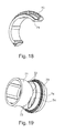
- FIGS. 13 and 14 and FIGS. 18 and 19 show ramp elements that are rotatable relative to one another, the ramp elements being connected to one another via oblique ramps, so that upon relative rotation of the ramp elements, an axial displacement of the ramp elements takes place.
- the Fig. 13 shows two ramp elements 60, 61, which are annular. In this case, the ramp element 60 has an annular gap 62 into which the ramp rings 63 of the ramp element 61 can engage. Both elements, the ramp ring 63 and the annular gap 62 have ramps 64, so that upon rotation of the ramp ring in the annular gap 62, an axial displacement of the ramp element 61 takes place relative to the ramp element 62.
- the Fig. 14 shows the arrangement of the ramp element 61 with the ramp ring 63 in the annular gap 62 of the ramp element 60, wherein there is no relative rotation, so that there is no axial displacement of the ramp element 61 relative to the ramp element 60.
- FIGS. 18 and 19 show a further embodiment of two ramp elements 70, 71, wherein the ramp ring 73 of the ramp element 71 engages in the ramp element 70 and cooperates there with ramps of the first ramp element.
- the ramps are arranged on the circumference of the ramp ring of the first ramp element or the second ramp element, so that the ramps can slide relative to each other and cause an axial displacement of the first ramp element relative to the second ramp element or vice versa.
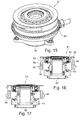
- the 15 to 17 show a further embodiment of a release device 81 with a housing 82 and a piston-cylinder unit 83 for acting on the release bearing 84.
- the piston-cylinder unit 83 is according to the embodiments of Fig. 5 to 8 or 10 or 12. The related description is also valid for the piston-cylinder unit 83.
- an actuating means provided as a ramp device 85, which provides two rotatable relative to each other ramp elements 86, 87.
- the ramp elements are rotatable relative to one another, wherein the respective ramps 88, 89 are supported slidingly against one another, wherein the ramp elements 86, 87 can be displaced in the axial direction by rotation of the ramps of the ramp elements. So is the ramp element 87 with the cup-like element 90 in connection, so that by extending the ramp member 87, the cup-like element 90 can be acted upon to urge the release bearing 84.
- the 15 to 17 show a release device with a piston-cylinder unit as the first actuating means and with a ramp device as the second actuating means.
- the ramp elements can be rotated relative to one another, for example by means of an actuator, in order to actuate the release bearing of the release device.
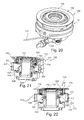
- FIGS. 20 to 22 show a further embodiment of a release device 100 according to the invention with a release bearing 101 with a first bearing ring 102 and with a second bearing ring 103rd
- a first actuating means 104 is provided as a piston-cylinder unit 105, which is arranged radially on the outside of a sleeve 106.
- the piston-cylinder unit 105 has an annular cylinder space 107 and an annular piston 108, which can slide in the cylinder space 107 in the axial direction.
- the cylinder space 107 can be acted upon by means of a pressure medium, such as a hydraulic fluid, wherein the cylinder space 107 can be connected to a fluid line via the fluid connection 109.
- FIG. 21 It can be seen that the piston 108 is arranged in a retracted position in the cylinder chamber 107 and the second bearing ring 103 is not acted upon by the displaceable sleeve 110.
- FIG. 22 It can be seen that the piston 108 is arranged in a preferred position in the cylinder chamber 107 and the second bearing ring 103 is acted upon by the displaceable sleeve 110. As a result, the release bearing is acted upon for actuating the clutch.
- the piston 108 and the sleeve 110 are preferably not firmly connected to each other, but they are displaced relative to each other. Thus, the piston 108 can move relative to the sleeve 110 without displacement of the sleeve 110.
- a ramp arrangement 111 is provided, which acts on a pot-like element 112, such as a shell, in the axial direction, which in turn is articulated on the second bearing ring 103.
- the ramp device consists of two annular elements 113, 114, which are rotatable relative to each other, wherein the annular elements ramps 120 at its periphery or distributed on at least one of their circumferences, which are supported against each other, so that upon a relative rotation of the ramp elements 113, 114 results in an axial displacement of the ramp elements 113, 114 relative to each other.
- the ramp elements 113, 114 are designed and arranged such that the first ramp element is designed as a substantially U-shaped element with two spaced legs 115 and the second ramp element 114 is arranged radially between the legs 115.
- the ramp element 114 In the extended state, the ramp element 114 is supported on the cup-like element 112 in the axial direction and actuates the second bearing ring via the cup-like element 112.
- the cup-like element 112 is arranged as a kind of shell around the release bearing 101, wherein the shell has a circular projection 116 on which the ramp element 114 is supported.
- the connection between the pot-like element 112 in the region of the projection 116 and the ramp element 114 is preferably formed without a fixed connection, so that the pot-like element 112 is displaceable without the ramp element, if the displacement of the release bearing via the first actuating element.
- first actuating element is actuated manually as a piston-cylinder unit by a pedal and the second actuating element is automated by an actuator, this can also be used to override the automated system by the manual system.
- a cable pull device which comprises a cable 117 which can be acted upon by a pull.
- the rope 117 winds around the first ramp element 113 on its circumference.
- the first ramp element 113 is rotated in the circumferential direction relative to the fixed second ramp element 114, whereby the ramps 120 of the ramp elements 113, 114 slide along each other and the second ramp element 114 is extended relative to the first ramp element 113 in the axial direction.
- the first ramp element is driven as an outer ring by means of the cable of the cable or alternatively via a belt or the like and rotated about its central axis.
- the belt can be driven, for example, by an electric motor both inside and outside a clutch bell.
- a cable may alternatively be designed such that a rope, for example by means of a kind of spindle or winch can be wound up and unwound to rotate the ramp devices relative to each other and to act on the release bearing and to move.
- a cable also offers the advantage that the drive motor of the cable can be installed in the vehicle at a selected place, the rope used can be guided through pulleys through pulleys. For the drive motor of the cable while a space can be selected, which is not dependent on the immediate space in and around the clutch bell.
- the outer ramp member 113 has a groove 118 between the two legs 115, in which the inner ramp member 114 is received.
- the ramps 120 are arranged on which the inner ramp element 114, which also has oppositely oriented ramps 120, extends by the rotational movement in the axial direction.
- the inner ramp member 114 on an axial guide to be prevented from turning with the outer ramp element.
- the inner ramp member presses upon extension to the pressure shell 116 and the cup-like element 112 and thereby displaced the release bearing, whereby the clutch is actuated.
- the actuation speed that is to say the rotational speed of the outer ramp element, can preferably be regulated in order to enable a smooth opening and closing of the clutch despite different driving situations and resistances.
- FIGS. 25 to 27 show a further embodiment of a ramp device 200, wherein the ramp device 200 consists of two hollow cylindrical elements 201, 202, each having on its inner surface 203 and on its outer surface 204 ramps 205, which are supported against each other, so that upon rotation of the two elements relative to each other the two elements are displaced axially to each other.
- the inner ring 202 moves out of the outer ring 201 axially when the outer ring 201 is rotated by means of the cable 206 of the cable pulling device.
- the outer ring is moved axially. Due to the flexibility of the cable, the drive can move in the direction of travel.
- the inner ring could thus be firmly connected to the housing, whereby the axial guidance could be omitted.
- the inner ring could thus also fall away completely and the ramps of the inner ring could be integrated directly into the housing of the release device.
- the outer rotating ring would then be rotatably mounted relative to the pressure shell. Meets the outer ring, which moves so by its rotational movement, on the shell, the elements begin to rub against each other, resulting in a torque on the firmly connected to the housing part of the bearing or the housing. This then takes place both when engaging and disengaging the clutch.
Landscapes
- Engineering & Computer Science (AREA)
- General Engineering & Computer Science (AREA)
- Mechanical Engineering (AREA)
- Hydraulic Clutches, Magnetic Clutches, Fluid Clutches, And Fluid Joints (AREA)
- Mechanical Operated Clutches (AREA)
Applications Claiming Priority (2)
| Application Number | Priority Date | Filing Date | Title |
|---|---|---|---|
| DE102013223871 | 2013-11-22 | ||
| DE102014207079 | 2014-04-14 |
Publications (2)
| Publication Number | Publication Date |
|---|---|
| EP2876322A2 true EP2876322A2 (fr) | 2015-05-27 |
| EP2876322A3 EP2876322A3 (fr) | 2016-04-20 |
Family
ID=51799034
Family Applications (1)
| Application Number | Title | Priority Date | Filing Date |
|---|---|---|---|
| EP14190887.1A Withdrawn EP2876322A3 (fr) | 2013-11-22 | 2014-10-29 | Dispositif de débrayage |
Country Status (2)
| Country | Link |
|---|---|
| EP (1) | EP2876322A3 (fr) |
| DE (1) | DE102014222081A1 (fr) |
Cited By (2)
| Publication number | Priority date | Publication date | Assignee | Title |
|---|---|---|---|---|
| EP2876324A3 (fr) * | 2013-11-22 | 2016-04-20 | Schaeffler Technologies AG & Co. KG | Dispositif de débrayage |
| CN120592982A (zh) * | 2025-08-06 | 2025-09-05 | 浙江柏瑞汽配股份有限公司 | 一种高强度离合执行机构及其加工方法 |
Family Cites Families (6)
| Publication number | Priority date | Publication date | Assignee | Title |
|---|---|---|---|---|
| CN1103140A (zh) * | 1993-09-13 | 1995-05-31 | 卢克摩擦片和离合器有限公司 | 分离装置 |
| ES2150832B1 (es) * | 1996-06-12 | 2001-06-16 | Fichtel & Sachs Ag | Dispositivo de maniobra para la maniobra, en particular maniobra neumatica, de un embrague de friccion. |
| DE19723362C2 (de) * | 1997-06-04 | 2002-07-18 | Zf Sachs Ag | Notbetätigung für eine automatisch betätigte Kraftfahrzeugkupplung |
| DE102005047930A1 (de) * | 2005-10-06 | 2007-04-12 | Zf Friedrichshafen Ag | Kupplungsvorrichtung eines Kraftfahrzeugs |
| DE102006057183A1 (de) * | 2006-12-01 | 2008-06-05 | Iav Gmbh Ingenieurgesellschaft Auto Und Verkehr | Verfahren und Vorrichtung zum Betätigen einer Reibungskupplung eines Fahrzeuges mit einem Handschaltgetriebe |
| WO2011076171A1 (fr) * | 2009-12-22 | 2011-06-30 | Schaeffler Technologies Gmbh & Co. Kg | Système d'actionnement pour un embrayage |
-
2014
- 2014-10-29 DE DE102014222081.5A patent/DE102014222081A1/de not_active Withdrawn
- 2014-10-29 EP EP14190887.1A patent/EP2876322A3/fr not_active Withdrawn
Non-Patent Citations (1)
| Title |
|---|
| None |
Cited By (3)
| Publication number | Priority date | Publication date | Assignee | Title |
|---|---|---|---|---|
| EP2876324A3 (fr) * | 2013-11-22 | 2016-04-20 | Schaeffler Technologies AG & Co. KG | Dispositif de débrayage |
| CN120592982A (zh) * | 2025-08-06 | 2025-09-05 | 浙江柏瑞汽配股份有限公司 | 一种高强度离合执行机构及其加工方法 |
| CN120592982B (zh) * | 2025-08-06 | 2025-10-31 | 浙江柏瑞汽配股份有限公司 | 一种高强度离合执行机构及其加工方法 |
Also Published As
| Publication number | Publication date |
|---|---|
| DE102014222081A1 (de) | 2015-05-28 |
| EP2876322A3 (fr) | 2016-04-20 |
Similar Documents
| Publication | Publication Date | Title |
|---|---|---|
| DE3031643A1 (de) | Servoeinrichtung, insbesondere zur bremskraftverstaerkung in einem kraftfahrzeug | |
| DE102011085839A1 (de) | Kupplungsvorrichtung mit zwei mittels einer Schiebemuffe koppelbaren Kupplungsteilen | |
| DE102010006569B4 (de) | Zweiwege-Aktuatorvorrichtung in einer Drehmomentübertragungsanordnung | |
| DE102012206936A1 (de) | Hybridgetriebe | |
| WO2018091026A1 (fr) | Dispositif d'embrayage | |
| WO2014075856A1 (fr) | Système de changement de vitesses et élément de changement de vitesses pour un tel système | |
| DE60315756T2 (de) | Doppelkupplungsgetriebe für ein Kraftfahrzeug | |
| WO2016165712A1 (fr) | Système d'accouplement | |
| DE19544352B4 (de) | Fahrzeuggetriebe | |
| DE202017106197U1 (de) | Antriebseinheit mit Schlupfbegrenzung und Antriebssystem-Trennfunktion | |
| WO2005036007A1 (fr) | Embrayage conçu pour une boite de vitesses | |
| WO2014075857A1 (fr) | Système de changement de vitesses et élément de changement de vitesses pour un tel système | |
| DE112014004796T5 (de) | Kupplungsvorrichtung für einen Retarder | |
| DE102006014141A1 (de) | Verfahren zur Steuerung einer automatisierten Reibungskupplung | |
| EP2876322A2 (fr) | Dispositif de débrayage | |
| DE1052315B (de) | Getriebe mit hydraulischer Steuereinrichtung zum Antrieb von Hubfahrzeugen | |
| DE102010023840B4 (de) | Reibkupplungsanordnung für einen Kraftfahrzeugantriebsstrang | |
| DE102014219361B4 (de) | Kupplungsbetätigungssystem | |
| WO2015149798A1 (fr) | Système d'actionnement de commutateur à cames dans une réalisation augmentant la dynamique par une élévation de la tension | |
| EP3724527A1 (fr) | Circuit à griffes | |
| DE102016222279A1 (de) | Feststellanordnung in einem Getriebe eines Fahrzeugs | |
| DE102014225267A1 (de) | Auflaufbremseinrichtung für einen Anhänger, Verfahren | |
| DE102006050956A1 (de) | Ausrückvorrichtung insbesondere zur Betätigung einer Fahrzeugkupplung | |
| DE102014217279A1 (de) | Doppelkupplung | |
| DE102015011405A1 (de) | Getriebeeinrichtung für ein Kraftfahrzeug |
Legal Events
| Date | Code | Title | Description |
|---|---|---|---|
| PUAI | Public reference made under article 153(3) epc to a published international application that has entered the european phase |
Free format text: ORIGINAL CODE: 0009012 |
|
| 17P | Request for examination filed |
Effective date: 20141029 |
|
| AK | Designated contracting states |
Kind code of ref document: A2 Designated state(s): AL AT BE BG CH CY CZ DE DK EE ES FI FR GB GR HR HU IE IS IT LI LT LU LV MC MK MT NL NO PL PT RO RS SE SI SK SM TR |
|
| AX | Request for extension of the european patent |
Extension state: BA ME |
|
| PUAL | Search report despatched |
Free format text: ORIGINAL CODE: 0009013 |
|
| AK | Designated contracting states |
Kind code of ref document: A3 Designated state(s): AL AT BE BG CH CY CZ DE DK EE ES FI FR GB GR HR HU IE IS IT LI LT LU LV MC MK MT NL NO PL PT RO RS SE SI SK SM TR |
|
| AX | Request for extension of the european patent |
Extension state: BA ME |
|
| RIC1 | Information provided on ipc code assigned before grant |
Ipc: F16D 48/02 20060101ALN20160316BHEP Ipc: F16D 23/12 20060101ALN20160316BHEP Ipc: F16D 25/08 20060101AFI20160316BHEP Ipc: F16D 23/14 20060101ALI20160316BHEP |
|
| R17P | Request for examination filed (corrected) |
Effective date: 20161020 |
|
| RBV | Designated contracting states (corrected) |
Designated state(s): AL AT BE BG CH CY CZ DE DK EE ES FI FR GB GR HR HU IE IS IT LI LT LU LV MC MK MT NL NO PL PT RO RS SE SI SK SM TR |
|
| 17Q | First examination report despatched |
Effective date: 20170613 |
|
| STAA | Information on the status of an ep patent application or granted ep patent |
Free format text: STATUS: THE APPLICATION IS DEEMED TO BE WITHDRAWN |
|
| 18D | Application deemed to be withdrawn |
Effective date: 20180915 |
|
| P01 | Opt-out of the competence of the unified patent court (upc) registered |
Effective date: 20230523 |