EP2876324A2 - Dispositif de débrayage - Google Patents
Dispositif de débrayage Download PDFInfo
- Publication number
- EP2876324A2 EP2876324A2 EP14190982.0A EP14190982A EP2876324A2 EP 2876324 A2 EP2876324 A2 EP 2876324A2 EP 14190982 A EP14190982 A EP 14190982A EP 2876324 A2 EP2876324 A2 EP 2876324A2
- Authority
- EP
- European Patent Office
- Prior art keywords
- piston
- cylinder
- cylinder units
- bearing
- bearing ring
- Prior art date
- Legal status (The legal status is an assumption and is not a legal conclusion. Google has not performed a legal analysis and makes no representation as to the accuracy of the status listed.)
- Withdrawn
Links
Images


Classifications
-
- F—MECHANICAL ENGINEERING; LIGHTING; HEATING; WEAPONS; BLASTING
- F16—ENGINEERING ELEMENTS AND UNITS; GENERAL MEASURES FOR PRODUCING AND MAINTAINING EFFECTIVE FUNCTIONING OF MACHINES OR INSTALLATIONS; THERMAL INSULATION IN GENERAL
- F16D—COUPLINGS FOR TRANSMITTING ROTATION; CLUTCHES; BRAKES
- F16D23/00—Details of mechanically-actuated clutches not specific for one distinct type
- F16D23/12—Mechanical clutch-actuating mechanisms arranged outside the clutch as such
- F16D23/14—Clutch-actuating sleeves or bearings; Actuating members directly connected to clutch-actuating sleeves or bearings
-
- F—MECHANICAL ENGINEERING; LIGHTING; HEATING; WEAPONS; BLASTING
- F16—ENGINEERING ELEMENTS AND UNITS; GENERAL MEASURES FOR PRODUCING AND MAINTAINING EFFECTIVE FUNCTIONING OF MACHINES OR INSTALLATIONS; THERMAL INSULATION IN GENERAL
- F16D—COUPLINGS FOR TRANSMITTING ROTATION; CLUTCHES; BRAKES
- F16D25/00—Fluid-actuated clutches
- F16D25/08—Fluid-actuated clutches with fluid-actuated member not rotating with a clutching member
- F16D25/082—Fluid-actuated clutches with fluid-actuated member not rotating with a clutching member the line of action of the fluid-actuated members co-inciding with the axis of rotation
- F16D25/083—Actuators therefor
-
- F—MECHANICAL ENGINEERING; LIGHTING; HEATING; WEAPONS; BLASTING
- F16—ENGINEERING ELEMENTS AND UNITS; GENERAL MEASURES FOR PRODUCING AND MAINTAINING EFFECTIVE FUNCTIONING OF MACHINES OR INSTALLATIONS; THERMAL INSULATION IN GENERAL
- F16D—COUPLINGS FOR TRANSMITTING ROTATION; CLUTCHES; BRAKES
- F16D48/00—External control of clutches
- F16D48/02—Control by fluid pressure
- F16D2048/0212—Details of pistons for primary or secondary cylinders especially adapted for fluid control
-
- F—MECHANICAL ENGINEERING; LIGHTING; HEATING; WEAPONS; BLASTING
- F16—ENGINEERING ELEMENTS AND UNITS; GENERAL MEASURES FOR PRODUCING AND MAINTAINING EFFECTIVE FUNCTIONING OF MACHINES OR INSTALLATIONS; THERMAL INSULATION IN GENERAL
- F16D—COUPLINGS FOR TRANSMITTING ROTATION; CLUTCHES; BRAKES
- F16D48/00—External control of clutches
- F16D48/02—Control by fluid pressure
- F16D2048/0227—Source of pressure producing the clutch engagement or disengagement action within a circuit; Means for initiating command action in power assisted devices
- F16D2048/0254—Double actuation, i.e. two actuation means can produce independently an engagement or disengagement of the clutch
Definitions
- the invention relates to a release device, in particular for disengaging a clutch.
- Release devices have become known in the art in various designs.
- Today disengaging devices for clutches are used, which are opened or closed by a displaceable release bearing.
- hydraulically actuated release devices or mechanically operated release devices are known.
- the device has a slave cylinder, which is connectable to a fluid line with a master cylinder or a hydraulic pump. Therefore, reference is made to the slave and encoder system, but instead of a master cylinder, a pump may always be present.
- a clutch pedal By pressing a clutch pedal, the piston of the clutch master cylinder is retracted, whereby the present in the master cylinder and in the rest of the system fluid is forced through the conduit system and thus an extension of the piston of the clutch slave cylinder is effected.
- the piston of the clutch slave cylinder thus presses with the provided in particular integrated release bearing on the plate spring of the clutch. Through this process, the clutch is disengaged or engaged or opened or closed and the power flow between the engine and transmission is thereby interrupted or produced.
- An embodiment of the invention relates to a release device with an axially displaceable release bearing, in particular for acting on an actuating element of a clutch, wherein the release bearing has a first bearing ring and a second bearing ring, wherein the first bearing ring serves to act on the actuating element and the second bearing ring for axial displacement of the release bearing can be acted upon by a first actuating means and a second actuating means, wherein the two actuating means are independently controllable, wherein the first actuating means comprises at least a first piston-cylinder unit, wherein each first piston-cylinder unit comprises a first cylinder, in which an axially displaceable first Piston is received, wherein the second bearing ring is acted upon by means of the at least one first piston of the at least one first piston-cylinder unit and wherein the second actuating center l has at least a second piston-cylinder unit, wherein each second piston-cylinder unit comprises a second cylinder in which an axially displaceable second piston is received, where
- the first actuating means comprises a plurality of first piston-cylinder units, wherein each first piston-cylinder unit comprises a first cylinder in which an axially displaceable first piston is accommodated, wherein the second bearing ring by means of the first piston of the first Piston-cylinder units can be acted upon.
- a first group of piston-cylinder units is defined, which are advantageously used simultaneously in one mode to disengage the clutch.
- first actuating means has a plurality of second piston-cylinder units, wherein each second piston-cylinder unit has a second cylinder in which an axially displaceable second piston is received, wherein the second bearing ring by means of the second piston of the second piston Cylinder units can be acted upon.
- a second group of piston-cylinder units is defined, which are advantageously used simultaneously in an alternative mode to disengage the clutch.
- first and second piston-cylinder units are provided, wherein the first and the second piston-cylinder units are distributed on the circumference of the release device and arranged alternately on the circumference.
- the piston-cylinder units of the groups alternate circumferentially to provide a more even force distribution.
- first and / or the second piston-cylinder units are designed as cylindrical piston-cylinder units with a circular cross-section. This results in a simple manufacturing, because the cylinder can be drilled or cast in this design easier.
- first piston-cylinder units and / or the second piston-cylinder units are designed as annular-segment-shaped or kidney-shaped piston-cylinder units with a circular-segment-shaped or kidney-shaped cross section.
- the cylinders of the first piston-cylinder units are short-circuited to one another by means of fluid connections and / or that the cylinders of the second piston-cylinder units are short-circuited to one another by means of fluid connections. This ensures that the piston-cylinder units of a group simultaneously actuate the release bearing.
- first piston-cylinder units and the second piston-cylinder units are arranged at the same radius. As a result, a preferred construction space-saving design is effected.
- the Fig. 1 to 7 show in various views a first embodiment of a release device 1 according to the invention.
- the disengaging device 1 has an axially displaceable release bearing 2, which in particular serves to act on an actuating element of a clutch. Due to the axial displacement of the release bearing 2, a clutch can be switched on or disengaged.
- the release bearing 2 has a first bearing ring 3 and a second bearing ring 4.
- the first bearing ring 3 is formed as a bearing outer ring and the second bearing ring 4 is formed as a bearing inner ring, between the first bearing ring 3 and the second bearing ring 4 rolling elements 5 are arranged to make the first bearing ring 3 relative to the second bearing ring 4 rotatable.
- the first bearing ring 3 serves to act on an actuating element, for example a clutch, while the second bearing ring 4 is used for the axial displacement of the release bearing 2.
- the first bearing ring 3 can be covered by a cover-like element 6, so that the actuating elements of the coupling can be acted upon by this cover-like element 6 of the first bearing ring 3.
- the release bearing 2 is received in a housing 7, within which the release bearing 2 is displaced in the axial direction.
- the housing 7 has according to the Fig. 2 to 7 two groups 8, 9 of piston-cylinder units 10, 11 on.
- the piston-cylinder units 10, 11 of the groups 8, 9 of piston-cylinder units are preferably each cylindrical and they are distributed on the circumference of the guide sleeve 12 of the housing 7.
- the piston-cylinder units 10 and the piston-cylinder units 11 are arranged substantially at the same radius.
- the groups 8, 9 are preferably configured in such a way or the piston-cylinder units 10, 11 of the groups 8, 9 arranged such that they alternate at the handling of the sleeve or the disengagement device.
- Each of the two piston-cylinder units 10, 11 has a cylinder 13, 14, a piston 15, 16 and possibly a sealing element which seals the cylinder space on the piston.
- the release bearing 2 can be actuated, thus actuating the clutch.
- the clutch there are two autonomous systems for actuating the clutch, which are arranged in the housing 7 and occupy substantially the same space as a conventional release device with only one cylinder-cylinder unit for the pedal operation.
- the housing 7 has a plurality of piston-cylinder units, which are supplied via a pressure medium connection with pressure medium. It may be advantageous if the piston-cylinder units of the respective group 8, 9 are fluid-connected and in each case can be supplied via a respective fluid line together with pressure medium. Thus, only one fluid connection for the respective group of piston-cylinder units can be provided on the housing.
- the respective piston-cylinder unit 10, 11 has a cylinder 13, 14 and a piston 15, 16, wherein the cylinder 13, 14 is sealed by a sealing ring, which is received by another ring, over this further ring of the piston is arranged, which is guided by the housing 7.
- the release bearing 2 is actuated.
- the release bearing 2 is biased by a spring 19, which is also arranged in the housing 7 and which is arranged radially outwardly of the piston-cylinder units.
- the release bearing 2 can be displaced along the guide sleeve 12 on the housing 7 of the automated system, without a pressure change in the cylinder 13 of the manual system or generally in the release system must be present.
- FIGS. 1 to 7 a total of six piston-cylinder units 10, 11 are installed, three for each group 8, 9. Alternatively, more or fewer piston-cylinder units 10, 11 per group can be integrated.
- the piston-cylinder units with their cylinders and pistons are preferably cylindrical. Therefore, they do not have to be secured against twisting in their leadership, resulting in a simplification of the components.
- FIGS. 4 to 7 show different states of actuation of the release bearing and the piston-cylinder units.
- the piston-cylinder units 10 and 11 are actuated and the pressure elements 17 and 18 protrude before.
- FIG. 4 the piston-cylinder units 11 are actuated while the piston-cylinder units 10 are not actuated.
- the pistons of the piston-cylinder units 11 project upwardly in the axial direction, and the pistons of the piston-cylinder units 10 are retracted.
- the clutch is actuated by means of the piston-cylinder units 11.
- FIG. 5 the piston-cylinder units 10 are actuated, while the piston-cylinder units 11 are actuated.
- the pistons of the piston-cylinder units 10 protrude upward in the axial direction, as well as the pistons of the piston-cylinder units 11 protrude.
- the clutch is actuated by means of the piston-cylinder units 11 and 10.
- piston-cylinder units 10 are actuated while the piston-cylinder units 11 are not actuated.
- the pistons of the piston-cylinder units 10 project upwardly in the axial direction and the pistons of the piston-cylinder units 11 are retracted.
- the clutch is actuated by means of the piston-cylinder units 10.
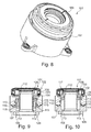
- the 8 to 14 show in various views, a further second embodiment of a release device 101 according to the invention.
- the disengaging device 101 has an axially displaceable release bearing 102, which in particular serves to act on an actuating element of a clutch. Due to the axial displacement of the release bearing 102, a clutch can be switched on or disengaged.
- the release bearing 102 has a first bearing ring 103 and a second bearing ring 104.
- the first bearing ring 103 formed as a bearing outer ring and the second bearing ring 104 is formed as a bearing inner ring, between the first bearing ring 103 and the second bearing ring 104 rolling elements 105 are arranged to make the first bearing ring 103 relative to the second bearing ring 104 rotatable.
- the first bearing ring 103 serves to act on an actuating element, for example a clutch, while the second bearing ring 104 is used for the axial displacement of the release bearing 102.
- the first bearing ring 103 can be covered by a cover-like element 106, so that the actuating elements of the coupling can be acted upon by this cover-like element 106 of the first bearing ring 103.
- the release bearing 102 is received in a housing 107 within which the release bearing 102 is displaceable in the axial direction.
- the housing 107 has according to the Fig. 9 to 14 two groups 108, 109 of piston-cylinder units 110, 111 on.
- the piston-cylinder units 110, 111 of the groups 108, 109 of piston-cylinder units are preferably each formed annular segment-shaped or kidney-shaped and they are arranged distributed on the circumference of the guide sleeve 112 of the housing 107.
- the piston-cylinder units 110 and the piston-cylinder units 111 are arranged substantially at the same radius.
- the groups 108, 109 configured in such a way or the piston-cylinder units 110, 111 of the groups 108, 109 arranged such that they alternate at the handling of the sleeve 112 and the release device.
- Each of the two piston-cylinder units 110, 111 has a cylinder 113, 114, a piston 115, 116 and possibly a sealing element which seals the cylinder space arranged on the piston.
- the piston 115 is displaced in the axial direction, wherein the piston 115 acts on its cylinder-side end a pressure chamber or pressure element 117, which acts on the bearing inner ring 104 at its opposite end.
- a pressure chamber or pressure element 117 which acts on the bearing inner ring 104 at its opposite end.
- the piston 116 is displaced in the axial direction, wherein the piston 116 acts on its one cylinder-side end a pressure chamber or a pressure element which acts on the bearing inner ring 104 at its opposite end.
- the piston 116 Upon displacement of the piston 116 in the axial direction of the bearing inner ring 104 is displaced in the axial direction, so that the release bearing 102 is also displaced in the axial direction.
- the release bearing 102 can be actuated to actuate the clutch.
- the clutch there are two autonomous systems for actuating the clutch, which are arranged in the housing 107 and occupy substantially the same space as a conventional release device with only one cylinder-cylinder unit for the pedal operation.
- the housing 107 has a plurality of piston-cylinder units, which are supplied via a pressure medium connection with pressure medium. It may be advantageous if the piston-cylinder units of the respective group 108, 109 are fluid-connected and in each case can be supplied via a respective fluid line together with pressure medium. So can the case 107 may be provided only one fluid port for each group of piston-cylinder units.
- the respective piston-cylinder unit 110, 111 has a cylinder 113, 114 and a piston 115, 116, wherein the cylinder 113, 114 is sealed by a sealing ring or a sealing element, wherein above this sealing element, the piston is arranged, which through the housing 107 is guided.
- the release bearing 102 is actuated.
- the release bearing 102 is biased by a spring 119, which is also arranged in the housing 7 and which is arranged radially outwardly of the piston-cylinder units.
- the release bearing 102 can be displaced along the guide sleeve 112 on the housing 107 of the automated system, without a pressure change in the cylinder 113 of the manual system or generally in the release system must be present.
- FIGS. 8 to 14 a total of four piston-cylinder units 110, 111 are installed, two for each group 108, 109. Alternatively, more or fewer piston-cylinder units 110, 111 per group 108, 109 can be integrated.
- the piston-cylinder units with their cylinders and pistons are preferably formed circular ring-shaped or kidney-shaped. Therefore, they do not have to be secured against twisting in their leadership, resulting in a simplification of the components.
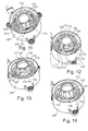
- FIGS. 11 to 14 show different states of actuation of the release bearing and the piston-cylinder units.
- the piston-cylinder units 110 and 11 are actuated and the pressure elements 117 and 118 protrude before.
- the piston-cylinder units 110 are actuated while the piston-cylinder units 111 are not actuated.
- the pistons of the piston-cylinder units 110 project upwardly in the axial direction and the pistons of the piston-cylinder units 111 are retracted.
- the clutch is actuated by means of the piston-cylinder units 110.
- the piston-cylinder units 110 are actuated, while the piston-cylinder units 111 are actuated.
- the pistons of the piston-cylinder units 110 project upwardly in the axial direction, as do the pistons of the piston-cylinder units 111.
- the clutch is actuated by means of the piston-cylinder units 111 and 110.
- the piston-cylinder units 111 are actuated while the piston-cylinder units 110 are not actuated.
- the pistons of the piston-cylinder units 111 project upwardly in the axial direction, and the pistons of the piston-cylinder units 110 are retracted.
- the clutch is actuated by means of the piston-cylinder units 111.
- first and second piston-cylinder units are shown in each case. However, this is not a limitation and it can also be provided a different number of first and second piston-cylinder units.
Landscapes
- Engineering & Computer Science (AREA)
- General Engineering & Computer Science (AREA)
- Mechanical Engineering (AREA)
- Hydraulic Clutches, Magnetic Clutches, Fluid Clutches, And Fluid Joints (AREA)
- Mechanical Operated Clutches (AREA)
Applications Claiming Priority (3)
| Application Number | Priority Date | Filing Date | Title |
|---|---|---|---|
| DE102013223871 | 2013-11-22 | ||
| DE102014207079 | 2014-04-14 | ||
| DE102014207267 | 2014-04-15 |
Publications (2)
| Publication Number | Publication Date |
|---|---|
| EP2876324A2 true EP2876324A2 (fr) | 2015-05-27 |
| EP2876324A3 EP2876324A3 (fr) | 2016-04-20 |
Family
ID=51799040
Family Applications (1)
| Application Number | Title | Priority Date | Filing Date |
|---|---|---|---|
| EP14190982.0A Withdrawn EP2876324A3 (fr) | 2013-11-22 | 2014-10-30 | Dispositif de débrayage |
Country Status (2)
| Country | Link |
|---|---|
| EP (1) | EP2876324A3 (fr) |
| DE (1) | DE102014222138A1 (fr) |
Family Cites Families (6)
| Publication number | Priority date | Publication date | Assignee | Title |
|---|---|---|---|---|
| JPS61180028A (ja) * | 1984-09-28 | 1986-08-12 | Daikin Mfg Co Ltd | 流体圧力式摩擦クラッチ |
| ES2150832B1 (es) * | 1996-06-12 | 2001-06-16 | Fichtel & Sachs Ag | Dispositivo de maniobra para la maniobra, en particular maniobra neumatica, de un embrague de friccion. |
| BR0108393A (pt) * | 2000-02-15 | 2003-03-11 | Luk Lamellen & Kupplungsbau | Dispositivo transmissor de torque |
| DE102005047930A1 (de) * | 2005-10-06 | 2007-04-12 | Zf Friedrichshafen Ag | Kupplungsvorrichtung eines Kraftfahrzeugs |
| WO2012095064A1 (fr) * | 2010-12-09 | 2012-07-19 | Schaeffler Technologies AG & Co. KG | Organe de débrayage pour un embrayage double comportant une détection de course |
| DE102014222081A1 (de) * | 2013-11-22 | 2015-05-28 | Schaeffler Technologies AG & Co. KG | Ausrückvorrichtung |
-
2014
- 2014-10-30 EP EP14190982.0A patent/EP2876324A3/fr not_active Withdrawn
- 2014-10-30 DE DE102014222138.2A patent/DE102014222138A1/de not_active Withdrawn
Non-Patent Citations (1)
| Title |
|---|
| None |
Also Published As
| Publication number | Publication date |
|---|---|
| EP2876324A3 (fr) | 2016-04-20 |
| DE102014222138A1 (de) | 2015-05-28 |
Similar Documents
| Publication | Publication Date | Title |
|---|---|---|
| DE102010060889B4 (de) | Synchronisiervorrichtung für ein Getriebe | |
| DE102010060890B4 (de) | Synchronisiervorrichtung für ein Getriebe | |
| EP3177843B1 (fr) | Embrayage multidisque axial | |
| DE102009053488B4 (de) | Einrichtung zur Übertragung einer Kolbenkraft einer Ein-/Ausrückeinrichtung auf die jeweilige Teilkupplung einer Doppelkupplung | |
| DE102015205832A1 (de) | Axiale Lamellenkupplung | |
| DE102014223033A1 (de) | Nasslaufende radiale Doppelkupplung | |
| EP3289247B1 (fr) | Dispositif d'assistance au changement de vitesses pour boîte de vitesses et dispositif de changement de vitesses pour motocyclette | |
| DE102011011269B4 (de) | Kompakte Drehmomentübertragungsanordnung | |
| EP2916026B1 (fr) | Système d'embrayage double | |
| DE102013224591A1 (de) | Kupplung | |
| DE102011104150B4 (de) | Drehmomentübertragungsvorrichtung mit Anlegeplattenablauf | |
| DE602004005587T2 (de) | Kupplungen | |
| DE102015213873B4 (de) | Axiale Lamellenkupplung | |
| WO2017028863A1 (fr) | Dispositif d'embrayage pour motorisation hybride | |
| DE102010032661A1 (de) | Ausrücksystem für eine Doppelkupplung | |
| DE102010030717A1 (de) | Bremskraftverstärker | |
| EP2876324A2 (fr) | Dispositif de débrayage | |
| DE102014222081A1 (de) | Ausrückvorrichtung | |
| DE102014219361B4 (de) | Kupplungsbetätigungssystem | |
| EP3056769B1 (fr) | Boite de vitesses comprenant un embrayage integre dans l'arbre primaire | |
| DE102012211876A1 (de) | Hydraulische Betätigungseinrichtung für eine Fahrzeugkupplung | |
| DE102017130363B4 (de) | Druckleitungselement für einen Druckbegrenzer | |
| DE2606502C3 (de) | Tandemhauptzylinder für eine hydraulische Fahrzeugbremsanlage | |
| DE102014222137A1 (de) | Ausrückvorrichtung | |
| DE102015204225A1 (de) | Aktormodul, insbesondere zur Betätigung einer Kupplung eines Fahrzeuges |
Legal Events
| Date | Code | Title | Description |
|---|---|---|---|
| PUAI | Public reference made under article 153(3) epc to a published international application that has entered the european phase |
Free format text: ORIGINAL CODE: 0009012 |
|
| 17P | Request for examination filed |
Effective date: 20141030 |
|
| AK | Designated contracting states |
Kind code of ref document: A2 Designated state(s): AL AT BE BG CH CY CZ DE DK EE ES FI FR GB GR HR HU IE IS IT LI LT LU LV MC MK MT NL NO PL PT RO RS SE SI SK SM TR |
|
| AX | Request for extension of the european patent |
Extension state: BA ME |
|
| PUAL | Search report despatched |
Free format text: ORIGINAL CODE: 0009013 |
|
| AK | Designated contracting states |
Kind code of ref document: A3 Designated state(s): AL AT BE BG CH CY CZ DE DK EE ES FI FR GB GR HR HU IE IS IT LI LT LU LV MC MK MT NL NO PL PT RO RS SE SI SK SM TR |
|
| AX | Request for extension of the european patent |
Extension state: BA ME |
|
| RIC1 | Information provided on ipc code assigned before grant |
Ipc: F16D 48/02 20060101ALN20160316BHEP Ipc: F16D 23/14 20060101ALI20160316BHEP Ipc: F16D 25/08 20060101AFI20160316BHEP |
|
| STAA | Information on the status of an ep patent application or granted ep patent |
Free format text: STATUS: THE APPLICATION IS DEEMED TO BE WITHDRAWN |
|
| 18D | Application deemed to be withdrawn |
Effective date: 20161021 |
|
| P01 | Opt-out of the competence of the unified patent court (upc) registered |
Effective date: 20230523 |