EP2876448B1 - Système de support de maintenance - Google Patents
Système de support de maintenance Download PDFInfo
- Publication number
- EP2876448B1 EP2876448B1 EP13823394.5A EP13823394A EP2876448B1 EP 2876448 B1 EP2876448 B1 EP 2876448B1 EP 13823394 A EP13823394 A EP 13823394A EP 2876448 B1 EP2876448 B1 EP 2876448B1
- Authority
- EP
- European Patent Office
- Prior art keywords
- pulse
- consumed
- average
- failure
- motor
- Prior art date
- Legal status (The legal status is an assumption and is not a legal conclusion. Google has not performed a legal analysis and makes no representation as to the accuracy of the status listed.)
- Active
Links
Images


Classifications
-
- G—PHYSICS
- G01—MEASURING; TESTING
- G01N—INVESTIGATING OR ANALYSING MATERIALS BY DETERMINING THEIR CHEMICAL OR PHYSICAL PROPERTIES
- G01N35/00—Automatic analysis not limited to methods or materials provided for in any single one of groups G01N1/00 - G01N33/00; Handling materials therefor
- G01N35/00584—Control arrangements for automatic analysers
- G01N35/00594—Quality control, including calibration or testing of components of the analyser
- G01N35/00613—Quality control
-
- G—PHYSICS
- G01—MEASURING; TESTING
- G01N—INVESTIGATING OR ANALYSING MATERIALS BY DETERMINING THEIR CHEMICAL OR PHYSICAL PROPERTIES
- G01N35/00—Automatic analysis not limited to methods or materials provided for in any single one of groups G01N1/00 - G01N33/00; Handling materials therefor
- G01N35/02—Automatic analysis not limited to methods or materials provided for in any single one of groups G01N1/00 - G01N33/00; Handling materials therefor using a plurality of sample containers moved by a conveyor system past one or more treatment or analysis stations
- G01N35/04—Details of the conveyor system
-
- G—PHYSICS
- G01—MEASURING; TESTING
- G01N—INVESTIGATING OR ANALYSING MATERIALS BY DETERMINING THEIR CHEMICAL OR PHYSICAL PROPERTIES
- G01N35/00—Automatic analysis not limited to methods or materials provided for in any single one of groups G01N1/00 - G01N33/00; Handling materials therefor
- G01N35/00584—Control arrangements for automatic analysers
- G01N35/00594—Quality control, including calibration or testing of components of the analyser
- G01N35/00613—Quality control
- G01N35/00623—Quality control of instruments
-
- G—PHYSICS
- G05—CONTROLLING; REGULATING
- G05B—CONTROL OR REGULATING SYSTEMS IN GENERAL; FUNCTIONAL ELEMENTS OF SUCH SYSTEMS; MONITORING OR TESTING ARRANGEMENTS FOR SUCH SYSTEMS OR ELEMENTS
- G05B19/00—Program-control systems
- G05B19/02—Program-control systems electric
- G05B19/18—Numerical control [NC], i.e. automatically operating machines, in particular machine tools, e.g. in a manufacturing environment, so as to execute positioning, movement or co-ordinated operations by means of program data in numerical form
- G05B19/406—Numerical control [NC], i.e. automatically operating machines, in particular machine tools, e.g. in a manufacturing environment, so as to execute positioning, movement or co-ordinated operations by means of program data in numerical form characterised by monitoring or safety
- G05B19/4062—Monitoring servoloop, e.g. overload of servomotor, loss of feedback or reference
-
- G—PHYSICS
- G01—MEASURING; TESTING
- G01N—INVESTIGATING OR ANALYSING MATERIALS BY DETERMINING THEIR CHEMICAL OR PHYSICAL PROPERTIES
- G01N35/00—Automatic analysis not limited to methods or materials provided for in any single one of groups G01N1/00 - G01N33/00; Handling materials therefor
- G01N35/00584—Control arrangements for automatic analysers
- G01N35/00594—Quality control, including calibration or testing of components of the analyser
- G01N35/00613—Quality control
- G01N35/00623—Quality control of instruments
- G01N2035/00643—Quality control of instruments detecting malfunctions in conveying systems
-
- G—PHYSICS
- G01—MEASURING; TESTING
- G01N—INVESTIGATING OR ANALYSING MATERIALS BY DETERMINING THEIR CHEMICAL OR PHYSICAL PROPERTIES
- G01N35/00—Automatic analysis not limited to methods or materials provided for in any single one of groups G01N1/00 - G01N33/00; Handling materials therefor
- G01N35/00584—Control arrangements for automatic analysers
- G01N35/00594—Quality control, including calibration or testing of components of the analyser
- G01N35/00613—Quality control
- G01N35/00623—Quality control of instruments
- G01N2035/00653—Quality control of instruments statistical methods comparing labs or apparatuses
-
- G—PHYSICS
- G01—MEASURING; TESTING
- G01N—INVESTIGATING OR ANALYSING MATERIALS BY DETERMINING THEIR CHEMICAL OR PHYSICAL PROPERTIES
- G01N35/00—Automatic analysis not limited to methods or materials provided for in any single one of groups G01N1/00 - G01N33/00; Handling materials therefor
- G01N35/02—Automatic analysis not limited to methods or materials provided for in any single one of groups G01N1/00 - G01N33/00; Handling materials therefor using a plurality of sample containers moved by a conveyor system past one or more treatment or analysis stations
- G01N35/04—Details of the conveyor system
- G01N2035/0439—Rotary sample carriers, i.e. carousels
- G01N2035/0446—Combinations of the above
-
- G—PHYSICS
- G01—MEASURING; TESTING
- G01N—INVESTIGATING OR ANALYSING MATERIALS BY DETERMINING THEIR CHEMICAL OR PHYSICAL PROPERTIES
- G01N35/00—Automatic analysis not limited to methods or materials provided for in any single one of groups G01N1/00 - G01N33/00; Handling materials therefor
- G01N35/02—Automatic analysis not limited to methods or materials provided for in any single one of groups G01N1/00 - G01N33/00; Handling materials therefor using a plurality of sample containers moved by a conveyor system past one or more treatment or analysis stations
- G01N35/04—Details of the conveyor system
- G01N2035/0496—Other details
-
- G—PHYSICS
- G05—CONTROLLING; REGULATING
- G05B—CONTROL OR REGULATING SYSTEMS IN GENERAL; FUNCTIONAL ELEMENTS OF SUCH SYSTEMS; MONITORING OR TESTING ARRANGEMENTS FOR SUCH SYSTEMS OR ELEMENTS
- G05B2219/00—Program-control systems
- G05B2219/30—Nc systems
- G05B2219/32—Operator till task planning
- G05B2219/32234—Maintenance planning
-
- G—PHYSICS
- G05—CONTROLLING; REGULATING
- G05B—CONTROL OR REGULATING SYSTEMS IN GENERAL; FUNCTIONAL ELEMENTS OF SUCH SYSTEMS; MONITORING OR TESTING ARRANGEMENTS FOR SUCH SYSTEMS OR ELEMENTS
- G05B2219/00—Program-control systems
- G05B2219/30—Nc systems
- G05B2219/37—Measurements
- G05B2219/37209—Estimate life of gear, drive
-
- G—PHYSICS
- G05—CONTROLLING; REGULATING
- G05B—CONTROL OR REGULATING SYSTEMS IN GENERAL; FUNCTIONAL ELEMENTS OF SUCH SYSTEMS; MONITORING OR TESTING ARRANGEMENTS FOR SUCH SYSTEMS OR ELEMENTS
- G05B2219/00—Program-control systems
- G05B2219/30—Nc systems
- G05B2219/45—Nc applications
- G05B2219/45092—Analysing or chemical synthesis robot, moving samples from station to station
Definitions
- the present invention relates to an automatic analyzer and a maintenance supporting system.
- an automatic analysis device for qualitative/quantitative analysis of a biological sample, such as blood and urine.
- Maintenance includes a case of performing component replacement due to duration of use, based on starting inspection, finishing inspection, periodic inspection, or the like, and a case of notifying an alarm to a service company when an automatic analysis device has fallen into an abnormal state and performing component replacement through checking and maintenance, as necessary, of the conditions of respective mechanisms.
- US2009/215183 discloses a specimen analyzer that includes a first holding section for holding a container; a first mechanism section for executing a first operation for the container on the first holding section; a second holding section for holding the container; a first transfer mechanism section for transferring the container from the first holding section to the second one; a second mechanism section for executing a second operation for the container on the second one; an error detector for detecting error in the first mechanism section; and an error controller for controlling the operation of the first holding section, the first and second operation so that the first operation and the transfer operation of the first holding section would be stopped while the second operation would be continued in case of the error in the first mechanism section.
- An abnormality control method of the analyzer and computer program product are also disclosed
- EP1166960 discloses a processing machine that is described as having the function of sensitively detecting collisions or other abnormalities to prevent the machine from being operated under abnormal conditions.
- Means is provided for detecting a load on a drive source for driving a movable member.
- Abnormality determining means is provided for determining the load is abnormal if the load as detected by the abnormality means exceeds an abnormality determination level.
- the abnormality determining means sets the abnormality determination level on the basis of the load as measured during the preceding driving operation of the movable member or the average of loads as measured during several past driving operations that are temporally close to the current one.
- expiration dates are placed on the respective components of the automatic analysis device, and a service person of a service company performs periodic replacement of mechanism components.
- failure of components due to aging is prevented, and down time of the automatic analysis device is reduced.
- component replacement is performed, according to an alarm output from an automatic analysis device or a certain period of time as an indication for replacing a mechanism component.
- an object of the present invention is to provide automatic analysis devices and a maintenance support system for preventing failures occurring during a cycle of periodic inspections and reducing down time of the automatic analysis devices.
- a maintenance support system according to claim 1.
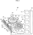
- FIG. 1 is a schematic structural diagram of the automatic analysis device 100 in the present embodiment.
- the automatic analysis device 100 will be described as one for measuring absorbance of light, however, the invention is not limited thereto.
- the automatic analysis device 100 includes a rack transportation device 103 for transporting specimen racks 102 on which plural specimen containers 101 containing specimen are mounted, a specimen dispensing mechanism 104, a reaction disc 106 on which plural reaction containers 105 are mounted on a concentric circle, a heat retaining bath 107, a constant temperature bath 108, a reagent disc 110 on which plural reagent bottles 109 containing various reagents are mounted on a concentric circle, a reagent dispensing mechanism 111, an agitation device 112, a cleaning device 113, a light source 114, a multi-wavelength photometer 115, an A/D convertor 116, a computer 117, an interface 118, an input device 119, a printer 120, a monitor 121, a storage device 122, a rack number reading device 123, and a specimen ID reading device 124.
- a rack transportation device 103 for transporting specimen racks 102 on which plural specimen containers 101 containing specimen are mounted
- the rack transportation device 103 is configured to be able to transport, along a transportation line, the specimen racks 102, on which plural specimen containers 101 containing specimen are mounted on the rotation circumference of the specimen dispensing mechanism 104 and along a tangent line of the reaction disc 106.
- the rack transportation device 103 is driven by a pulse motor and controlled by the computer 117 via the interface 118.
- the rack number reading device 123 and the specimen ID reading device 124 are disposed along the transportation line of the rack transportation device 103. Incidentally, information having been read by the rack number reading device 123 and the specimen ID reading device 124 is input via the interface 118 to the computer 117.
- the specimen dispensing mechanism 104 is configured to be able to dispense a predetermined amount of the specimen in a specimen container 101 into a reaction container 105, using a specimen dispensing probe 104A and under control by the computer 117.
- the specimen dispensing mechanism 104 has a rotation driving mechanism (not shown) for moving the specimen dispensing probe 104A between the specimen container 101 and the reaction container 105. Further, the specimen dispensing mechanism 104 has a driving mechanism (not shown) for vertically moving the specimen dispensing probe 104A.
- the rotation driving mechanism and the driving mechanism of the specimen dispensing mechanism 104 are configured to be driven by a pulse motor and controlled via the interface 118 by the computer 117.
- reaction disc 106 On the reaction disc 106, plural reaction containers 105 are disposed on a circle concentric with the reaction disc 106.
- the reaction disc 106 is rotatably installed and has a rotation driving mechanism (not shown).
- the rotation driving mechanism of the reaction disc 106 is driven by a pulse motor and is controlled via the interface 118 by the computer 117.
- the reaction disc 106 is configured to be maintained at a predetermined temperature by the heat retaining bath 107 communicated with the constant temperature bath 108.
- reagent disc 110 On the reagent disc 110, plural reagent bottles 109 containing various reagent are mounted on a circle concentric with the reagent disc 110.
- the reagent disc 110 is rotatably installed and has a rotation driving mechanism (not shown).
- the rotation driving mechanism of the reagent disc 110 is driven by a pulse motor and is controlled via the interface 118 by the computer 117.
- the reagent dispensing mechanism 111 is configured to be able to dispense a predetermined amount of the reagent in a reagent bottle 109 into a reaction container 105, using a reagent dispensing probe 111A and under control by the computer 117.
- the reagent dispensing mechanism 111 has a rotation driving mechanism (not shown) for moving the reagent dispensing probe 111A between the reagent bottle 109 and the reaction container 105.
- reagent dispensing mechanism 111 has a driving mechanism (not shown) for vertically moving the reagent dispensing probe 111A.
- the rotation driving mechanism and the driving mechanism of the reagent dispensing mechanism 111 are configured to be driven by a pulse motor and controlled via the interface 118 by the computer 117.
- the agitation device 112 is configured to be able to agitate specimen and reagent dispensed in a reaction container 105.
- the agitation device 112 has a driving mechanism (not shown).
- the driving mechanism of the agitation device 112 is driven by a pulse motor and controlled via the interface 118 by the computer 117.
- the cleaning device 113 is configured to be able to clean the reaction containers 105.
- the agitation device 112 has a driving mechanism (not shown).
- the driving mechanism of the cleaning device 113 is configured to be driven by a pulse motor and controlled via the interface 118 by the computer 117.
- the multi-wavelength photometer 115 is configured to be able to measure the absorbance of light of the liquid (reaction solution) in a reaction container 105, using the light source 114.
- a measured absorbance signal is converted by the A/D convertor 116 from an analog signal into a digital signal to be input via the interface 118 to the computer 117.
- the computer 117 is configured to be able to control the entire automatic analysis device 100 by controlling the respective mechanisms.
- the computer 117 is connected via the interface 118 with the input device 119 for input of various operation conditions, the printer 120 and the monitor 121, which are output devices, and the storage device 122 for storing various data.
- the computer 117 controls the rack transportation device 103 to transport the specimen racks 102.
- An individual serial number (rack number) is assigned to the each specimen rack 102, and the each serial number is read by the rack number reading device 123 during when the specimen rack 102 is transported on the transportation line. Further, when a specimen ID number is assigned to the specimen container 101 held by a specimen rack 102, the specimen ID number is read by the specimen ID reading device 124. Incidentally, information having been read by the rack number reading device 123 and the specimen ID reading device 124 is input via the interface 118 to the computer 117.
- the computer 117 controls the rack transportation device 103 to move the specimen racks 102 until a first specimen container 101 held by a specimen rack 102 comes to a position directly under the specimen dispensing probe 104A of the specimen dispensing mechanism 104. Then, the computer 117 controls the specimen dispensing mechanism 104 to dispense a predetermined amount of the reagent contained in the first specimen container 101 into a first reaction container 105, using the specimen dispensing probe 104A.
- the computer 117 controls the rack transportation device 103 and moves the specimen racks 102 until a second specimen container 101 held by a specimen rack 102 comes to the position directly under the specimen dispensing probe 104A of the specimen dispensing mechanism 104. Further, the computer 117 controls the reaction disc 106 to rotate it by a predetermined angle. Then, the computer 117 controls the specimen dispensing mechanism 104 to dispense a predetermined amount of the reagent contained in the second specimen container 101 into a second reaction container 105, using the specimen dispensing probe 104A. Subsequently, the rest of specimens are dispensed similarly into reaction containers 105.
- a reaction container 105 into which a specimen has been dispensed rotates and moves on the reaction disc 106 by a rotation operation of the reaction disc 106.
- the computer 117 controls the reagent disc 110 to move it until a reagent bottle 109 containing a certain reagent comes to a position directly under the reagent dispensing probe 111A of the reagent dispensing mechanism 111.
- the computer 117 controls the reagent dispensing mechanism 111 to dispense the reagent contained in the reagent bottle 109 into the reaction container 105 by a predetermined amount, using the reagent dispensing probe 111A.
- the computer 117 controls the agitation device 112 to agitate liquid (reaction solution) of the specimen and the reagent having been dispensed into the reaction container 105.
- the absorbance of light of the liquid (reaction solution) in the reaction container 105 is measured with the light source 114 and the multi-wavelength photometer 115, and a signal of the measured absorbance is converted by the A/D convertor 116 into a digital signal to be input via the interface 118 to the computer 117.
- a reaction container 105 on which analysis has been finished is cleaned by the cleaning device 113.
- the computer 117 converts the absorbance into the concentration of the component of the measuring object in the specimen, and creates data that is associated with information (rack number, specimen ID) having been read by the rack number reading device 123 and the specimen ID reading device 124.
- the created data is printed out from the printer 120 via the interface 118, displayed in a screen on the monitor 121, and stored in the storage device 122.
- mechanisms are arranged such that the rack transportation device 103, the specimen dispensing mechanism 104, the reaction disc 106, the reagent disc 110, the reagent dispensing mechanism 111, the agitation device 112, and the cleaning device 113 are driven by pulse motors.
- the operation speeds (operation angular velocities) and the operation distances (operation angles) of the respective mechanisms are controlled by pulses (electrical power transmission amount) to the pulse motors.
- pulses electrical power transmission amount
- a pulse value which is larger than the pulse value for an operation speed (operation angular velocity) and an operation distance (operation angular velocity) as the operation purpose, is set as a driving pulse value.
- the computer 117 of the automatic analysis device 100 in the present embodiment is configured to store and accumulate driving pulse values and consumed pulse quantities in the storage device 122, recognizing a pulse quantity having been consumed, on a driving pulse value for driving a pulse motor, during actual driving of the pulse motor as a consumed pulse quantity. Further, remaining pulse quantities, each of which is obtained by subtracting a consumed pulse quantity from a driving pulse value, are also stored and accumulated in the storage device 122.
- the consumed pulse quantity becomes a value that gradually deviates from a driving pulse value, and later deviates up to a value that prohibits operation for the purpose, and phenomenon of some failure occurs.
- the computer 117 of an automatic analysis device 100 in the present embodiment functions as means for transmitting information of the driving pulse values, the consumed pulse quantities, and the remaining pulse quantities of a pulse motor stored and accumulated in the storage device 122, to a maintenance support system 200 (a later described maintenance server 202 (see FIG. 2 )) in the present embodiment via the interface 118. Further, in addition to the information of the driving pulse values, the consumed pulse quantities, and the remaining pulse quantities, it is also possible to transmit the number of driving times and the failure state of the pulse motor.
- the maintenance support system 200 (see the later-described FIG. 2 ) in the present embodiment is configured to be able to specify a mechanism with a pulse motor in a tendency of abnormality, in other words, a mechanism with a possibility of occurrence of failure, by collecting, accumulating, and monitoring driving pulse values, consumed pulse quantities, and remaining pulse quantities from plural facilities where automatic analysis devices 100 are installed. Further, by adding the specified mechanism to the check items of periodical inspection, it is possible to prevent failures occurring during a cycle of periodic inspections and reducing down time of the automatic analysis device 100.
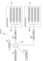
- FIG. 2 is a structural block diagram of the maintenance support system 200 for the automatic analysis devices 100 in the present embodiment.
- the maintenance support system 200 for automatic analysis devices 100 is provided with remote terminals 201A, 201B, a maintenance server 202, and a WEB server 203, which are connected by communication lines 205A, 205B, and 206.
- symbol 204 represents a user terminal.
- the remote terminal 201A is connected with automatic analysis devices 100 installed in the inspection room A via the communication line (for example, LAN (Local Area Network)) 205A.
- the remote terminal 201B is connected with automatic analysis devices 100 installed in the inspection room B via the communication line (for example, LAN) 205B.
- the remote terminals 201A, 201B are communicatably connected with the maintenance server 202 via the communication line (for example, a dedicated line or Internet connection) 206. Further, the maintenance server 202, the WEB server 203, and the user terminal 204 are communicatably connected via the communication line 206.
- the communication line for example, a dedicated line or Internet connection
- the each automatic analysis device 100 is configured to be able to transmit the driving pulse value, the consumed pulse quantity, and the remaining pulse quantity of a pulse motor arranged for a corresponding mechanism, via the remote terminal 201A or 201B to the maintenance server 202.
- driving pulse values, consumed pulse quantities, and remaining pulse quantities, which are output from the respective automatic analysis devices 100 will be collectively referred to as pulse information.
- An automatic analysis device 100 is configured to be able to transmit a notification of occurrence of failure together with pulse information to the maintenance server 202 in case that a failure has occurred on a pulse motor arranged for the corresponding mechanism.
- the maintenance server 202 is configured to be able to obtain and accumulate pulse information on pulse motors arranged for the respective mechanisms of an automatic analysis device 100 via the remote terminal 201A or 201B.
- a pulse information table 300 in which pulse information is accumulated will be described later, referring to FIG. 3 .
- the maintenance server 202 can compute the average values of various information of pulse motors at the times of failure occurrence and store the computed average values.
- a pulse motor average value table 400 at failure occurrence will be described later, referring to FIG. 4 .
- the maintenance server 202 is configured to be able to determine whether or not a pulse motor, whose pulse information has been obtained, has a possibility of occurrence of failure, based on the pulse information table 300 (see FIG. 3 ) and the pulse motor average value table 400 (see FIG. 4 ). If the maintenance server 202 has determined a possibility of occurrence of failure, the maintenance server 202 can notify the user terminal 204 of this determination by a mail.
- determination on whether or not there is a possibility of occurrence of failure is made, for example, such that a possibility of occurrence of failure is determined if the consumed pulse quantity of a pulse motor has deviated by a predetermined or a larger quantity from the average value of consumed pulse quantities of pulse motors in all the inspection rooms, or has approximated to a failure value (the average value at the times of failure occurrence).
- determination on whether or not a failure possibly occurs will be described later, referring to FIG. 5 .
- the WEB server 203 is configured to be able to obtain pulse information and the like from the maintenance server 202, and store a screen 500 (see FIG. 5 described later) displaying graphs, a screen 600 (see FIG. 6 described later) displaying the states of the respective mechanisms of a single automatic analysis device 100, and a screen 700 (see FIG. 7 described later) displaying the states of automatic analysis devices 100.
- the user terminal 204 is a terminal installed in a service company for services of maintenance and inspection and the like of automatic analysis devices 100, and is connected to the WEB server 203 via the communication line 206 to be able to refer to screens ( FIG. 5 , FIG. 6 , and FIG. 7 described later) stored in the WEB server 203.
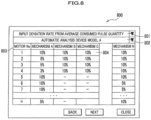
- the user terminal 204 is configured to be able to display an input screen 800 (see FIG. 8 described later) and input a deviation rate and an approximation rate for determination of possibility of failure occurrence.
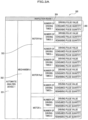
- the pulse information table 300 for storing pulse information of pulse motors is, as shown in FIG. 3 , formed with the automatic analysis device numbers 301 of automatic analysis devices 100 installed in respective inspection rooms, the mechanism numbers 302 of respective mechanisms configuring the automatic analysis devices 100, the pulse motor numbers 303 of pulse motors configuring the mechanisms, and pulse information 305 for the respective numbers of driving times 304 of the pulse motors.
- the pulse information 305 is formed with driving pulse values, consumed pulse quantities, and remaining pulse quantities.
- pulse information of all the mechanisms of the automatic analysis devices 100 installed in all the inspection rooms is accumulated in the maintenance server 202.
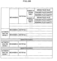
- the pulse motor average value table 400 stores various average values computed from the numbers of driving times at failure occurrence on pulse motors and pulse information (driving pulse value, consumed pulse quantity, and remaining pulse quantity), which have been extracted out from the pulse information, of all the inspection rooms, accumulated in the pulse information table 300 (see FIG. 3 ).
- the pulse motor average value table 400 is formed for an individual model 401 of automatic analysis device 100. Further, the pulse motor average value table 400 stores the average numbers of at-failure driving times 405, which are obtained by computing the averages of numbers of driving times at the time of failure occurrence, and the average at-failure pulse quantities 406, which are obtained by computing the averages of consumed pulse quantities at the time of failure occurrence, for the respective mechanism numbers 402, the respective pulse motor numbers 403, and the respective driving pulse values 404.
- deviation rates (deviation rates from the average pulse quantities) 407 of deviations from the average consumed pulse quantities (see graph 506 in FIG. 5 described later) for detecting the possibility of failure occurrence on a pulse motor are stored.
- approximation rates (approximation rates to at-failure pulse quantities) 408 to the average at-failure pulse quantities 406 (see graph 507 in FIG. 5 described later) for detecting the possibility of failure occurrence on a pulse motor are stored.
- deviation rates 407 and approximation rates 408 may be a preset value and may be, as described later, a value input via an input screen 800 (see FIG. 8 ).
- the graphs on the screen 500 represent a pulse quantity 501 by y-axis (vertical axis) and a number of driving times 502 by x-axis (horizontal axis).
- the graphs are created for an individual driving pulse value 504 of a pulse motor 503 as an object.
- the graph 505 is a graph of consumed pulse quantities plotted for a corresponding individual driving pulse value 504 of a pulse motor 503 to be an object.
- the graph 506 is a graph of average consumed pulse quantities of the same pulse motors (pulse motors installed at the same position of the same mechanism of the same model) as the pulse motor 503 to be an object in terms of motor, having all the facilities as the object of averaging.
- the graph 507 is a graph of averages of the consumed pulse quantities at failure occurrence on the same pulse motors (the average at-failure pulse quantities 406 in FIG. 4 ).
- a possibility of failure occurrence is determined if the graph 505 has deviated from the graph 506 of plotted average consumed pulse quantities by a predetermined deviation rate (the average pulse quantity deviation rate 407 in FIG. 4 ) or more. Further, a possibility of failure occurrence is also determined if the graph 505 has approximated to the graph 507 representing the average at-failure pulse quantities 406 by a predetermined approximation rate (approximation rate to at-failure pulse quantity 408 in FIG. 4 ) or more. Incidentally, if a possibility of failure occurrence has been determined, for example, the display color of the graph 505 is changed for visual recognition of the possibility of a failure.
- the screen 600 shown in FIG. 6 is displayed for an individual automatic analysis device 601 and displayed in a matrix structure 602, wherein respective mechanisms of an automatic analysis device are disposed along the horizontal axis, and motor numbers are disposed along the vertical axis such that a single cell corresponds to a single pulse motor.
- a cell of a pulse motor determined, in association with the graphs shown in FIG. 5 , to have a possibility of failure occurrence is represented by an indication 603 with a different mark and in a different color.
- a screen 500 (see FIG. 5 ) displaying variation in the consumed pulse quantity of an individual pulse motor is displayed.
- the screen 700 shown in FIG. 7 is displayed in a matrix structure 701 in which the numbers of inspection rooms are disposed along the vertical axis and the numbers of automatic analysis devices in the respective inspection rooms are disposed along the horizontal axis such that a single cell corresponds to a single automatic analysis device.
- a cell of an automatic analysis device having a pulse motor determined, in association with the graphs shown in FIG. 5 , to have a possibility of failure occurrence is represented by an indication 702 with a different mark or in a different color.
- a screen 600 (see FIG. 6 ) displaying the states of pulse motors of the corresponding individual automatic analysis device is displayed.
- the input screen shown in FIG. 8 allows switching between input of a deviation rate and input of an approximation rate by pull-down 801, and allows switching between models of automatic analysis device by pull-down 802.
- the screen is displayed in a matrix structure 803, in which the respective mechanisms of an automatic analysis device are disposed along the horizontal axis and the numbers of motors are disposed along the vertical axis, for an individual model of automatic analysis device selected via the pull-down 802 such that a single cell corresponds to a single pulse motor.
- a deviation rate or an approximation rate selected via the pull-down 801 can be input.
- a deviation rate or an approximation rate having been input via the input screen 800 is stored via the WEB server 203 and the communication line 206 into the deviation rate 407 or the approximation rate 408 of the pulse motor average value table 400 (see FIG. 4 ) of the maintenance server 202.
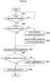
- FIG. 9 is a flowchart showing the process by the maintenance server 202.
- an automatic analysis device 100 is configured to be able to transmit a telegram message in which pulse information (driving pulse value, consumed pulse quantity, remaining pulse quantity), the number of driving times, and the failure state of a pulse motor are stored.
- step S901 the maintenance server 202 determines whether or not it has received, from an automatic analysis device 100, a telegram message including pulse information (driving pulse value, consumed pulse quantity, remaining pulse quantity), the number of driving times, and a failure state. If the maintenance server 202 has not yet received a telegram message including pulse information (S901, No), the maintenance server 202 repeats step S901 until it obtains such a telegram message. When the maintenance server 202 has obtained a telegram message including pulse information (S901, Yes), the process by the maintenance server 202 proceeds to step 5902.
- pulse information driving pulse value, consumed pulse quantity, remaining pulse quantity
- step S902 the maintenance server 202 determines whether or not the telegram message, obtained in step 5901, including pulse information includes a notification representing that the failure state of the pulse motor is failure. If a notification of the failure of the pulse motor is included (S902, Yes), the process by the maintenance server 202 proceeds to step sS903. If a notification of failure of the pulse motor is not included (S902, No), the process by the maintenance server 202 proceeds to step S905.
- step S903 the maintenance server 202 computes an average value, based on the consumed pulse quantity obtained in step S901 and at-failure consumed pulse quantities in the past, and updates the average at-failure pulse quantities 406 of the pulse motor average value table 400 (see FIG. 4 ).
- step S904 the maintenance server 202 computes an average value, based on the number of driving times in the telegram message obtained in step 5901 and the numbers of at-failure driving times in the past, and updates the average number of at-failure driving times 405 in the pulse motor average value table 400 (see FIG. 4 ). Then, the process by the maintenance server 202 proceeds to step S905.
- step S905 the maintenance server 202 accumulates the pulse information and the number of driving times obtained in step S901 into the pulse information table 300 (see FIG. 3 ).
- the maintenance server 202 computes the average consumed pulse quantity (see graph 506 in FIG. 5 ) of the same pulse motors (pulse motors being of the same model and installed at the same position of the same mechanism), as the pulse motor to be the object, in all the facilities as the object of averaging computation.
- step S906 the maintenance server 202 detects the abnormal tendency of a pulse motor. Concretely, if the consumed pulse quantity obtained in step S901 deviates at a larger rate than the deviation rate 407 (see FIG. 4 ) from the average consumed pulse quantity (see graph 506 in FIG. 5 ), a possibility of failure occurrence is determined, and an abnormal tendency is thus detected. Further, if the consumed pulse quantity obtained in step S901 approximates to the average at-failure pulse quantity 406 (see FIG. 4 ) at the approximation rate 408 (see FIG. 4 ), a possibility of failure occurrence on the pulse motor is determined, and an abnormal tendency is thus detected.
- step S907 If an abnormal tendency is detected (S906, Yes), the process by the maintenance server 202 proceeds to step S907. If an abnormal tendency is not detected (S906, No), the process by the maintenance server 202 proceeds to step S908.
- step S907 the maintenance server 202 notifies the user terminal 204 of abnormality. Then, the process by the maintenance server 202 proceeds to step S908.
- step S908 the maintenance server 202 updates the screens 500, 600, and 700 (see FIG. 5 , FIG. 6 , and FIG. 7 ), and transmits them to the WEB server 203.
- the maintenance server 202 is configured to obtain pulse information from an automatic analysis device 100, detect abnormal tendency of a pulse motor (possibility of failure occurrence), and notify the user terminal 204 of it.
- the average number of at-failure driving times 405 (see FIG. 4 ) is updated in real time, and it is thereby possible to appropriately predict a time of component replacement and specify a mechanism that needs improvement. Still further, it is possible to detect a mechanism with a high failure frequency in an automatic analysis device 100, and thereby obtain a target of improvement in an automatic analysis device in operation or an automatic analysis device under development.
- an automatic analysis device and a maintenance support system in the present embodiment are not limited to the arrangement in the foregoing embodiment, and various changes and modifications can be made in a range without departing from the purpose of the invention.
- a driving pulse value, a consumed pulse quantity, and a remaining pulse quantity are transmitted as pulse information from an automatic analysis device 100 to the maintenance support system 200, however, the invention is not limited thereto.
- the remaining one can be computed by Expression (1). Accordingly, arrangement may be made such that any two out of a driving pulse value, a consumed pulse quantity, and a remaining pulse quantity are transmitted as pulse information from an automatic analysis device 100 to the maintenance support system 200, and information of the remaining one is computed by Expression (1) on the maintenance support system 200.
- the maintenance server 202 detects an abnormal tendency (see S906 in FIG. 9 ), based on a consumed pulse quantity, however, the invention is not limited thereto.
- an abnormal tendency may be detected, based on a remaining pulse quantity. That is, when the remaining pulse quantity of a pulse motor as an object has deviated from the average value of the remaining pulse quantities of pulse motors in all the inspection rooms by a predetermined quantity or more or has approximated to the average value of at-failure-occurrence remaining pulse quantities by a predetermined quantity or more, the maintenance server 202 determines that the pulse motor has a possibility of failure occurrence, and thus detects an abnormal tendency.
Landscapes
- Engineering & Computer Science (AREA)
- Quality & Reliability (AREA)
- Physics & Mathematics (AREA)
- General Physics & Mathematics (AREA)
- General Health & Medical Sciences (AREA)
- Chemical & Material Sciences (AREA)
- Analytical Chemistry (AREA)
- Biochemistry (AREA)
- Life Sciences & Earth Sciences (AREA)
- Health & Medical Sciences (AREA)
- Immunology (AREA)
- Pathology (AREA)
- Human Computer Interaction (AREA)
- Manufacturing & Machinery (AREA)
- Automation & Control Theory (AREA)
- Automatic Analysis And Handling Materials Therefor (AREA)
Claims (8)
- Système de support de maintenance (200), comprenant :
un serveur de maintenance (202) qui est configuré pour :obtenir des informations d'impulsions transmises à partir de plusieurs dispositifs d'analyse automatique (100) dont chacun inclut un mécanisme entraîné par un moteur à impulsions (103, 104, 106, 110-113) et des moyens de transmission (117, 118) pour transmettre les informations d'impulsions sous forme d'informations d'impulsions incluant deux parmi une valeur d'impulsions d'entraînement définie pour entraîner le moteur à impulsions, une quantité d'impulsions consommée qui est une quantité d'impulsions ayant été consommée pendant l'entraînement réel du moteur à impulsions, et une quantité d'impulsions restantes qui est obtenue en soustrayant la quantité d'impulsions consommée de la valeur d'impulsions d'entraînement ;accumuler au moins les quantités d'impulsions consommées ;déterminer si oui ou non une quantité d'impulsions consommée obtenue d'un moteur à impulsions s'écarte, d'un niveau d'écart prédéterminé ou plus, d'une quantité d'impulsions consommée moyenne qui est une valeur moyenne des quantités d'impulsions consommées accumulées ; etdéterminer que le moteur à impulsions est dans une tendance anormale lorsqu'il est déterminé que la quantité d'impulsions consommée obtenue du moteur à impulsions s'écarte, du niveau d'écart prédéterminé ou plus, de la quantité d'impulsions consommée moyenne. - Système de support de maintenance (200) selon la revendication 1, dans lequel le serveur de maintenance (202) est configuré pour :déterminer si oui ou non la quantité d'impulsions consommée obtenue d'un moteur à impulsions se rapproche d'une quantité d'impulsions moyenne en panne par un niveau d'approximation prédéterminé ou plus, la quantité d'impulsions moyenne en panne étant une valeur moyenne des quantités d'impulsions consommées lors de l'apparition d'une panne sur des moteurs à impulsions ; etdéterminer que le moteur à impulsions est dans une tendance anormale lorsqu'il est déterminé que la quantité d'impulsions consommée obtenue du moteur à impulsions se rapproche de la quantité moyenne d'impulsions en panne par le niveau d'approximation prédéterminé ou plus.
- Système de support de maintenance (200), comprenant :
un serveur de maintenance (202) qui est configuré pour :obtenir des informations d'impulsions transmises à partir de plusieurs dispositifs d'analyse automatique (100) dont chacun inclut un mécanisme entraîné par un moteur à impulsions (103, 104, 106, 110-113) et des moyens de transmission (117, 118) pour transmettre les informations d'impulsions sous forme d'informations d'impulsions incluant deux parmi une valeur d'impulsions d'entraînement définie pour entraîner le moteur à impulsions, une quantité d'impulsions consommée qui est une quantité d'impulsions ayant été consommée pendant l'entraînement réel du moteur à impulsions, et une quantité d'impulsions restantes qui est obtenue en soustrayant la quantité d'impulsions consommée de la valeur d'impulsions d'entraînement ;accumuler au moins les quantités d'impulsions restantes ;déterminer si oui ou non une quantité d'impulsions restante obtenue d'un moteur à impulsions s'écarte, d'un niveau d'écart prédéterminé ou plus, d'une quantité d'impulsions restante moyenne qui est une valeur moyenne des quantités d'impulsions restantes accumulées ; etdéterminer que le moteur à impulsions est dans une tendance anormale lorsqu'il est déterminé que la quantité d'impulsions restante obtenue du moteur à impulsions s'écarte, du niveau d'écart prédéterminé ou plus, de la quantité d'impulsions restante moyenne. - Système de support de maintenance (200) selon la revendication 3, dans lequel le serveur de maintenance (202) est configuré pour :déterminer si oui ou non la quantité d'impulsions restante obtenue d'un moteur à impulsions se rapproche d'une quantité d'impulsions moyenne en panne qui est une valeur moyenne des quantités d'impulsion restantes lors de l'apparition d'une panne sur des moteurs à impulsions, par un niveau d'approximation prédéterminé ou plus ; etdéterminer que le moteur à impulsions est dans une tendance anormale si l'approximation a été déterminée.
- Système de support de maintenance (200) selon la revendication 1 ou 3, comprenant :
des moyens de réglage (800) pour régler le niveau d'écart prédéterminé. - Système de support de maintenance (200) selon la revendication 2 ou 4, comprenant :
des moyens de réglage (800) pour régler le niveau d'approximation prédéterminé. - Système de support de maintenance (200) selon la revendication 2, dans lequel le système de support de maintenance (200) est configuré pour créer un écran d'affichage pour afficher la quantité d'impulsions consommée d'un moteur à impulsions, la quantité d'impulsions consommée moyenne et la quantité d'impulsions en panne moyenne.
- Système de support de maintenance (200) selon la revendication 4, dans lequel le système de support de maintenance (200) est configuré pour créer un écran d'affichage pour afficher la quantité d'impulsions restante d'un moteur à impulsions, la quantité d'impulsions restante moyenne et la quantité d'impulsions moyenne en panne.
Applications Claiming Priority (2)
| Application Number | Priority Date | Filing Date | Title |
|---|---|---|---|
| JP2012162307A JP6046935B2 (ja) | 2012-07-23 | 2012-07-23 | 保守サポートシステム |
| PCT/JP2013/069936 WO2014017494A1 (fr) | 2012-07-23 | 2013-07-23 | Dispositif d'analyse automatique et système de support de maintenance |
Publications (3)
| Publication Number | Publication Date |
|---|---|
| EP2876448A1 EP2876448A1 (fr) | 2015-05-27 |
| EP2876448A4 EP2876448A4 (fr) | 2016-03-16 |
| EP2876448B1 true EP2876448B1 (fr) | 2023-12-20 |
Family
ID=49997303
Family Applications (1)
| Application Number | Title | Priority Date | Filing Date |
|---|---|---|---|
| EP13823394.5A Active EP2876448B1 (fr) | 2012-07-23 | 2013-07-23 | Système de support de maintenance |
Country Status (5)
| Country | Link |
|---|---|
| US (1) | US10031147B2 (fr) |
| EP (1) | EP2876448B1 (fr) |
| JP (1) | JP6046935B2 (fr) |
| CN (1) | CN104487848B (fr) |
| WO (1) | WO2014017494A1 (fr) |
Families Citing this family (5)
| Publication number | Priority date | Publication date | Assignee | Title |
|---|---|---|---|---|
| WO2018022351A1 (fr) * | 2016-07-25 | 2018-02-01 | Siemens Healthcare Diagnostics Inc. | Procédés et appareil de prédiction et de prévention de la défaillance d'instruments de diagnostic in vitro |
| JP6914799B2 (ja) * | 2017-10-06 | 2021-08-04 | 日本電子株式会社 | 自動分析装置及び動作量補正方法 |
| US12111327B2 (en) * | 2018-12-06 | 2024-10-08 | Hitachi High-Tech Corporation | Automatic analyzer with a control unit for displaying background maintenance operation notifications |
| US20220137013A1 (en) * | 2019-02-28 | 2022-05-05 | Shimadzu Corporation | Component management system for analysis device and component management program |
| EP3961221B1 (fr) * | 2019-04-24 | 2025-05-28 | Hitachi High-Tech Corporation | Dispositif d'analyse automatique et procédé de guidage de maintenance dans un dispositif d'analyse automatique |
Family Cites Families (12)
| Publication number | Priority date | Publication date | Assignee | Title |
|---|---|---|---|---|
| JPH07129236A (ja) * | 1993-10-28 | 1995-05-19 | Murata Mach Ltd | 位置ずれ検出装置 |
| JP2000116980A (ja) * | 1998-10-16 | 2000-04-25 | Nippon Kentetsu Co Ltd | 洗濯機の負荷量判定方法 |
| JP2001004635A (ja) * | 1999-06-18 | 2001-01-12 | Hitachi Ltd | 自動分析装置 |
| JP2002001633A (ja) * | 2000-06-19 | 2002-01-08 | Murata Mach Ltd | 異常負荷検知機能を備えた加工機 |
| JP3654645B2 (ja) * | 2002-05-21 | 2005-06-02 | 三菱電機株式会社 | モータ駆動系の異常検出装置 |
| JP4152351B2 (ja) * | 2004-06-17 | 2008-09-17 | シスメックス株式会社 | 臨床検体処理装置および臨床検体処理システム |
| JP2007133290A (ja) * | 2005-11-14 | 2007-05-31 | Matsushita Electric Ind Co Ltd | プラズマディスプレイ装置 |
| JP4578518B2 (ja) * | 2007-12-28 | 2010-11-10 | シスメックス株式会社 | 臨床検体処理装置および臨床検体処理システム |
| JP5486160B2 (ja) * | 2008-02-27 | 2014-05-07 | シスメックス株式会社 | 検体分析装置及びその異常制御方法、並びに検体分析装置用プログラム |
| DE102010007349B4 (de) * | 2009-02-09 | 2018-03-01 | Fuji Electric Co., Ltd. | Anomalienüberwachungsvorrichtung |
| JP5452254B2 (ja) * | 2010-01-28 | 2014-03-26 | シスメックス株式会社 | 検体分析装置 |
| JP5735852B2 (ja) * | 2011-05-02 | 2015-06-17 | シスメックス株式会社 | 臨床検査装置の管理方法、臨床検査システム、及びメンテナンス用管理装置 |
-
2012
- 2012-07-23 JP JP2012162307A patent/JP6046935B2/ja active Active
-
2013
- 2013-07-23 WO PCT/JP2013/069936 patent/WO2014017494A1/fr not_active Ceased
- 2013-07-23 US US14/416,376 patent/US10031147B2/en active Active
- 2013-07-23 EP EP13823394.5A patent/EP2876448B1/fr active Active
- 2013-07-23 CN CN201380039396.4A patent/CN104487848B/zh active Active
Also Published As
| Publication number | Publication date |
|---|---|
| US10031147B2 (en) | 2018-07-24 |
| WO2014017494A1 (fr) | 2014-01-30 |
| JP6046935B2 (ja) | 2016-12-21 |
| EP2876448A1 (fr) | 2015-05-27 |
| US20150260742A1 (en) | 2015-09-17 |
| JP2014021034A (ja) | 2014-02-03 |
| EP2876448A4 (fr) | 2016-03-16 |
| CN104487848B (zh) | 2016-04-06 |
| CN104487848A (zh) | 2015-04-01 |
Similar Documents
| Publication | Publication Date | Title |
|---|---|---|
| EP2876448B1 (fr) | Système de support de maintenance | |
| JP5425487B2 (ja) | 自動分析装置 | |
| JP3156550B2 (ja) | 試薬管理の方法および装置 | |
| US20140119994A1 (en) | Sample analyzer | |
| US20090281930A1 (en) | Automatic analyzer, order management system, and order management method | |
| JP2010151519A (ja) | 自動分析装置 | |
| JP2003294763A (ja) | 自動分析装置及びその管理システム | |
| JP6815794B2 (ja) | 自動分析装置 | |
| JP7038734B2 (ja) | 自動分析装置 | |
| JP2012026815A (ja) | 精度管理システム | |
| WO2014115591A1 (fr) | Dispositif de mesure électrochimique | |
| JP2004219352A (ja) | 分析装置及び管理システム | |
| US20250147055A1 (en) | Data analysis method, data analysis system, and computer | |
| EP2881741B1 (fr) | Dispositif d'analyse automatique | |
| EP3896454B1 (fr) | Automate d'analyse | |
| JP3603019B2 (ja) | 生化学自動分析装置 | |
| JP4966879B2 (ja) | 自動分析装置 | |
| US9945881B2 (en) | Automatic analysis device | |
| JP5393710B2 (ja) | 自動分析装置および自動分析装置の制御方法 | |
| JPH0627743B2 (ja) | 自動分析装置 | |
| JP6025397B2 (ja) | 自動分析装置 | |
| JP6039940B2 (ja) | 自動分析装置 | |
| JP4933198B2 (ja) | 自動分析装置 | |
| JP6076756B2 (ja) | 自動分析システム | |
| JP2017151054A (ja) | 自動分析装置 |
Legal Events
| Date | Code | Title | Description |
|---|---|---|---|
| PUAI | Public reference made under article 153(3) epc to a published international application that has entered the european phase |
Free format text: ORIGINAL CODE: 0009012 |
|
| 17P | Request for examination filed |
Effective date: 20150123 |
|
| AK | Designated contracting states |
Kind code of ref document: A1 Designated state(s): AL AT BE BG CH CY CZ DE DK EE ES FI FR GB GR HR HU IE IS IT LI LT LU LV MC MK MT NL NO PL PT RO RS SE SI SK SM TR |
|
| AX | Request for extension of the european patent |
Extension state: BA ME |
|
| DAX | Request for extension of the european patent (deleted) | ||
| RA4 | Supplementary search report drawn up and despatched (corrected) |
Effective date: 20160212 |
|
| RIC1 | Information provided on ipc code assigned before grant |
Ipc: G01N 35/00 20060101AFI20160208BHEP |
|
| RAP1 | Party data changed (applicant data changed or rights of an application transferred) |
Owner name: HITACHI HIGH-TECH CORPORATION |
|
| STAA | Information on the status of an ep patent application or granted ep patent |
Free format text: STATUS: EXAMINATION IS IN PROGRESS |
|
| 17Q | First examination report despatched |
Effective date: 20210331 |
|
| GRAP | Despatch of communication of intention to grant a patent |
Free format text: ORIGINAL CODE: EPIDOSNIGR1 |
|
| STAA | Information on the status of an ep patent application or granted ep patent |
Free format text: STATUS: GRANT OF PATENT IS INTENDED |
|
| INTG | Intention to grant announced |
Effective date: 20230705 |
|
| GRAS | Grant fee paid |
Free format text: ORIGINAL CODE: EPIDOSNIGR3 |
|
| GRAA | (expected) grant |
Free format text: ORIGINAL CODE: 0009210 |
|
| STAA | Information on the status of an ep patent application or granted ep patent |
Free format text: STATUS: THE PATENT HAS BEEN GRANTED |
|
| AK | Designated contracting states |
Kind code of ref document: B1 Designated state(s): AL AT BE BG CH CY CZ DE DK EE ES FI FR GB GR HR HU IE IS IT LI LT LU LV MC MK MT NL NO PL PT RO RS SE SI SK SM TR |
|
| REG | Reference to a national code |
Ref country code: GB Ref legal event code: FG4D |
|
| REG | Reference to a national code |
Ref country code: DE Ref legal event code: R096 Ref document number: 602013085082 Country of ref document: DE |
|
| REG | Reference to a national code |
Ref country code: CH Ref legal event code: EP |
|
| REG | Reference to a national code |
Ref country code: IE Ref legal event code: FG4D |
|
| PG25 | Lapsed in a contracting state [announced via postgrant information from national office to epo] |
Ref country code: GR Free format text: LAPSE BECAUSE OF FAILURE TO SUBMIT A TRANSLATION OF THE DESCRIPTION OR TO PAY THE FEE WITHIN THE PRESCRIBED TIME-LIMIT Effective date: 20240321 |
|
| REG | Reference to a national code |
Ref country code: LT Ref legal event code: MG9D |
|
| PG25 | Lapsed in a contracting state [announced via postgrant information from national office to epo] |
Ref country code: LT Free format text: LAPSE BECAUSE OF FAILURE TO SUBMIT A TRANSLATION OF THE DESCRIPTION OR TO PAY THE FEE WITHIN THE PRESCRIBED TIME-LIMIT Effective date: 20231220 |
|
| REG | Reference to a national code |
Ref country code: NL Ref legal event code: MP Effective date: 20231220 |
|
| PG25 | Lapsed in a contracting state [announced via postgrant information from national office to epo] |
Ref country code: ES Free format text: LAPSE BECAUSE OF FAILURE TO SUBMIT A TRANSLATION OF THE DESCRIPTION OR TO PAY THE FEE WITHIN THE PRESCRIBED TIME-LIMIT Effective date: 20231220 |
|
| PG25 | Lapsed in a contracting state [announced via postgrant information from national office to epo] |
Ref country code: LT Free format text: LAPSE BECAUSE OF FAILURE TO SUBMIT A TRANSLATION OF THE DESCRIPTION OR TO PAY THE FEE WITHIN THE PRESCRIBED TIME-LIMIT Effective date: 20231220 Ref country code: GR Free format text: LAPSE BECAUSE OF FAILURE TO SUBMIT A TRANSLATION OF THE DESCRIPTION OR TO PAY THE FEE WITHIN THE PRESCRIBED TIME-LIMIT Effective date: 20240321 Ref country code: FI Free format text: LAPSE BECAUSE OF FAILURE TO SUBMIT A TRANSLATION OF THE DESCRIPTION OR TO PAY THE FEE WITHIN THE PRESCRIBED TIME-LIMIT Effective date: 20231220 Ref country code: ES Free format text: LAPSE BECAUSE OF FAILURE TO SUBMIT A TRANSLATION OF THE DESCRIPTION OR TO PAY THE FEE WITHIN THE PRESCRIBED TIME-LIMIT Effective date: 20231220 Ref country code: BG Free format text: LAPSE BECAUSE OF FAILURE TO SUBMIT A TRANSLATION OF THE DESCRIPTION OR TO PAY THE FEE WITHIN THE PRESCRIBED TIME-LIMIT Effective date: 20240320 |
|
| REG | Reference to a national code |
Ref country code: AT Ref legal event code: MK05 Ref document number: 1642887 Country of ref document: AT Kind code of ref document: T Effective date: 20231220 |
|
| PG25 | Lapsed in a contracting state [announced via postgrant information from national office to epo] |
Ref country code: NL Free format text: LAPSE BECAUSE OF FAILURE TO SUBMIT A TRANSLATION OF THE DESCRIPTION OR TO PAY THE FEE WITHIN THE PRESCRIBED TIME-LIMIT Effective date: 20231220 |
|
| PG25 | Lapsed in a contracting state [announced via postgrant information from national office to epo] |
Ref country code: SE Free format text: LAPSE BECAUSE OF FAILURE TO SUBMIT A TRANSLATION OF THE DESCRIPTION OR TO PAY THE FEE WITHIN THE PRESCRIBED TIME-LIMIT Effective date: 20231220 Ref country code: RS Free format text: LAPSE BECAUSE OF FAILURE TO SUBMIT A TRANSLATION OF THE DESCRIPTION OR TO PAY THE FEE WITHIN THE PRESCRIBED TIME-LIMIT Effective date: 20231220 Ref country code: NO Free format text: LAPSE BECAUSE OF FAILURE TO SUBMIT A TRANSLATION OF THE DESCRIPTION OR TO PAY THE FEE WITHIN THE PRESCRIBED TIME-LIMIT Effective date: 20240320 Ref country code: NL Free format text: LAPSE BECAUSE OF FAILURE TO SUBMIT A TRANSLATION OF THE DESCRIPTION OR TO PAY THE FEE WITHIN THE PRESCRIBED TIME-LIMIT Effective date: 20231220 Ref country code: LV Free format text: LAPSE BECAUSE OF FAILURE TO SUBMIT A TRANSLATION OF THE DESCRIPTION OR TO PAY THE FEE WITHIN THE PRESCRIBED TIME-LIMIT Effective date: 20231220 Ref country code: HR Free format text: LAPSE BECAUSE OF FAILURE TO SUBMIT A TRANSLATION OF THE DESCRIPTION OR TO PAY THE FEE WITHIN THE PRESCRIBED TIME-LIMIT Effective date: 20231220 |
|
| PG25 | Lapsed in a contracting state [announced via postgrant information from national office to epo] |
Ref country code: IS Free format text: LAPSE BECAUSE OF FAILURE TO SUBMIT A TRANSLATION OF THE DESCRIPTION OR TO PAY THE FEE WITHIN THE PRESCRIBED TIME-LIMIT Effective date: 20240420 |
|
| PG25 | Lapsed in a contracting state [announced via postgrant information from national office to epo] |
Ref country code: AT Free format text: LAPSE BECAUSE OF FAILURE TO SUBMIT A TRANSLATION OF THE DESCRIPTION OR TO PAY THE FEE WITHIN THE PRESCRIBED TIME-LIMIT Effective date: 20231220 Ref country code: CZ Free format text: LAPSE BECAUSE OF FAILURE TO SUBMIT A TRANSLATION OF THE DESCRIPTION OR TO PAY THE FEE WITHIN THE PRESCRIBED TIME-LIMIT Effective date: 20231220 |
|
| PG25 | Lapsed in a contracting state [announced via postgrant information from national office to epo] |
Ref country code: SK Free format text: LAPSE BECAUSE OF FAILURE TO SUBMIT A TRANSLATION OF THE DESCRIPTION OR TO PAY THE FEE WITHIN THE PRESCRIBED TIME-LIMIT Effective date: 20231220 |
|
| PG25 | Lapsed in a contracting state [announced via postgrant information from national office to epo] |
Ref country code: SM Free format text: LAPSE BECAUSE OF FAILURE TO SUBMIT A TRANSLATION OF THE DESCRIPTION OR TO PAY THE FEE WITHIN THE PRESCRIBED TIME-LIMIT Effective date: 20231220 Ref country code: SK Free format text: LAPSE BECAUSE OF FAILURE TO SUBMIT A TRANSLATION OF THE DESCRIPTION OR TO PAY THE FEE WITHIN THE PRESCRIBED TIME-LIMIT Effective date: 20231220 Ref country code: RO Free format text: LAPSE BECAUSE OF FAILURE TO SUBMIT A TRANSLATION OF THE DESCRIPTION OR TO PAY THE FEE WITHIN THE PRESCRIBED TIME-LIMIT Effective date: 20231220 Ref country code: IT Free format text: LAPSE BECAUSE OF FAILURE TO SUBMIT A TRANSLATION OF THE DESCRIPTION OR TO PAY THE FEE WITHIN THE PRESCRIBED TIME-LIMIT Effective date: 20231220 Ref country code: IS Free format text: LAPSE BECAUSE OF FAILURE TO SUBMIT A TRANSLATION OF THE DESCRIPTION OR TO PAY THE FEE WITHIN THE PRESCRIBED TIME-LIMIT Effective date: 20240420 Ref country code: EE Free format text: LAPSE BECAUSE OF FAILURE TO SUBMIT A TRANSLATION OF THE DESCRIPTION OR TO PAY THE FEE WITHIN THE PRESCRIBED TIME-LIMIT Effective date: 20231220 Ref country code: CZ Free format text: LAPSE BECAUSE OF FAILURE TO SUBMIT A TRANSLATION OF THE DESCRIPTION OR TO PAY THE FEE WITHIN THE PRESCRIBED TIME-LIMIT Effective date: 20231220 Ref country code: AT Free format text: LAPSE BECAUSE OF FAILURE TO SUBMIT A TRANSLATION OF THE DESCRIPTION OR TO PAY THE FEE WITHIN THE PRESCRIBED TIME-LIMIT Effective date: 20231220 |
|
| PG25 | Lapsed in a contracting state [announced via postgrant information from national office to epo] |
Ref country code: PT Free format text: LAPSE BECAUSE OF FAILURE TO SUBMIT A TRANSLATION OF THE DESCRIPTION OR TO PAY THE FEE WITHIN THE PRESCRIBED TIME-LIMIT Effective date: 20240422 Ref country code: PL Free format text: LAPSE BECAUSE OF FAILURE TO SUBMIT A TRANSLATION OF THE DESCRIPTION OR TO PAY THE FEE WITHIN THE PRESCRIBED TIME-LIMIT Effective date: 20231220 |
|
| REG | Reference to a national code |
Ref country code: DE Ref legal event code: R097 Ref document number: 602013085082 Country of ref document: DE |
|
| PG25 | Lapsed in a contracting state [announced via postgrant information from national office to epo] |
Ref country code: DK Free format text: LAPSE BECAUSE OF FAILURE TO SUBMIT A TRANSLATION OF THE DESCRIPTION OR TO PAY THE FEE WITHIN THE PRESCRIBED TIME-LIMIT Effective date: 20231220 |
|
| PLBE | No opposition filed within time limit |
Free format text: ORIGINAL CODE: 0009261 |
|
| STAA | Information on the status of an ep patent application or granted ep patent |
Free format text: STATUS: NO OPPOSITION FILED WITHIN TIME LIMIT |
|
| PG25 | Lapsed in a contracting state [announced via postgrant information from national office to epo] |
Ref country code: SI Free format text: LAPSE BECAUSE OF FAILURE TO SUBMIT A TRANSLATION OF THE DESCRIPTION OR TO PAY THE FEE WITHIN THE PRESCRIBED TIME-LIMIT Effective date: 20231220 |
|
| PG25 | Lapsed in a contracting state [announced via postgrant information from national office to epo] |
Ref country code: SI Free format text: LAPSE BECAUSE OF FAILURE TO SUBMIT A TRANSLATION OF THE DESCRIPTION OR TO PAY THE FEE WITHIN THE PRESCRIBED TIME-LIMIT Effective date: 20231220 Ref country code: DK Free format text: LAPSE BECAUSE OF FAILURE TO SUBMIT A TRANSLATION OF THE DESCRIPTION OR TO PAY THE FEE WITHIN THE PRESCRIBED TIME-LIMIT Effective date: 20231220 |
|
| 26N | No opposition filed |
Effective date: 20240923 |
|
| PG25 | Lapsed in a contracting state [announced via postgrant information from national office to epo] |
Ref country code: MC Free format text: LAPSE BECAUSE OF FAILURE TO SUBMIT A TRANSLATION OF THE DESCRIPTION OR TO PAY THE FEE WITHIN THE PRESCRIBED TIME-LIMIT Effective date: 20231220 |
|
| REG | Reference to a national code |
Ref country code: CH Ref legal event code: PL |
|
| PG25 | Lapsed in a contracting state [announced via postgrant information from national office to epo] |
Ref country code: LU Free format text: LAPSE BECAUSE OF NON-PAYMENT OF DUE FEES Effective date: 20240723 |
|
| GBPC | Gb: european patent ceased through non-payment of renewal fee |
Effective date: 20240723 |
|
| PG25 | Lapsed in a contracting state [announced via postgrant information from national office to epo] |
Ref country code: LU Free format text: LAPSE BECAUSE OF NON-PAYMENT OF DUE FEES Effective date: 20240723 |
|
| PG25 | Lapsed in a contracting state [announced via postgrant information from national office to epo] |
Ref country code: CH Free format text: LAPSE BECAUSE OF NON-PAYMENT OF DUE FEES Effective date: 20240731 Ref country code: BE Free format text: LAPSE BECAUSE OF NON-PAYMENT OF DUE FEES Effective date: 20240731 |
|
| PG25 | Lapsed in a contracting state [announced via postgrant information from national office to epo] |
Ref country code: GB Free format text: LAPSE BECAUSE OF NON-PAYMENT OF DUE FEES Effective date: 20240723 |
|
| REG | Reference to a national code |
Ref country code: BE Ref legal event code: MM Effective date: 20240731 |
|
| PGFP | Annual fee paid to national office [announced via postgrant information from national office to epo] |
Ref country code: FR Payment date: 20250610 Year of fee payment: 13 |
|
| PG25 | Lapsed in a contracting state [announced via postgrant information from national office to epo] |
Ref country code: IE Free format text: LAPSE BECAUSE OF NON-PAYMENT OF DUE FEES Effective date: 20240723 |
|
| PGFP | Annual fee paid to national office [announced via postgrant information from national office to epo] |
Ref country code: DE Payment date: 20250528 Year of fee payment: 13 |
|
| PG25 | Lapsed in a contracting state [announced via postgrant information from national office to epo] |
Ref country code: CY Free format text: LAPSE BECAUSE OF FAILURE TO SUBMIT A TRANSLATION OF THE DESCRIPTION OR TO PAY THE FEE WITHIN THE PRESCRIBED TIME-LIMIT; INVALID AB INITIO Effective date: 20130723 |
|
| PG25 | Lapsed in a contracting state [announced via postgrant information from national office to epo] |
Ref country code: HU Free format text: LAPSE BECAUSE OF FAILURE TO SUBMIT A TRANSLATION OF THE DESCRIPTION OR TO PAY THE FEE WITHIN THE PRESCRIBED TIME-LIMIT; INVALID AB INITIO Effective date: 20130723 |