EP2878331B1 - Tête d'électrode avec une enveloppe présentant des parties en forme de segments d'une enveloppe de cylindre - Google Patents
Tête d'électrode avec une enveloppe présentant des parties en forme de segments d'une enveloppe de cylindre Download PDFInfo
- Publication number
- EP2878331B1 EP2878331B1 EP14190627.1A EP14190627A EP2878331B1 EP 2878331 B1 EP2878331 B1 EP 2878331B1 EP 14190627 A EP14190627 A EP 14190627A EP 2878331 B1 EP2878331 B1 EP 2878331B1
- Authority
- EP
- European Patent Office
- Prior art keywords
- electrode
- head
- electrode head
- parts
- housing
- Prior art date
- Legal status (The legal status is an assumption and is not a legal conclusion. Google has not performed a legal analysis and makes no representation as to the accuracy of the status listed.)
- Active
Links
- 229910052751 metal Inorganic materials 0.000 claims description 9
- 239000002184 metal Substances 0.000 claims description 9
- 239000003814 drug Substances 0.000 claims description 4
- 239000004696 Poly ether ether ketone Substances 0.000 claims description 3
- JUPQTSLXMOCDHR-UHFFFAOYSA-N benzene-1,4-diol;bis(4-fluorophenyl)methanone Chemical compound OC1=CC=C(O)C=C1.C1=CC(F)=CC=C1C(=O)C1=CC=C(F)C=C1 JUPQTSLXMOCDHR-UHFFFAOYSA-N 0.000 claims description 3
- 239000004033 plastic Substances 0.000 claims description 3
- 229920002530 polyetherether ketone Polymers 0.000 claims description 3
- 210000000056 organ Anatomy 0.000 claims description 2
- 229940079593 drug Drugs 0.000 claims 2
- 238000007789 sealing Methods 0.000 description 6
- 239000004020 conductor Substances 0.000 description 4
- 238000005192 partition Methods 0.000 description 4
- 238000011161 development Methods 0.000 description 3
- 230000018109 developmental process Effects 0.000 description 3
- 229920001296 polysiloxane Polymers 0.000 description 3
- 239000004810 polytetrafluoroethylene Substances 0.000 description 3
- 229920001343 polytetrafluoroethylene Polymers 0.000 description 3
- 238000010276 construction Methods 0.000 description 2
- 238000002347 injection Methods 0.000 description 2
- 239000007924 injection Substances 0.000 description 2
- 238000004519 manufacturing process Methods 0.000 description 2
- 229910001069 Ti alloy Inorganic materials 0.000 description 1
- RTAQQCXQSZGOHL-UHFFFAOYSA-N Titanium Chemical compound [Ti] RTAQQCXQSZGOHL-UHFFFAOYSA-N 0.000 description 1
- 230000036982 action potential Effects 0.000 description 1
- 239000002260 anti-inflammatory agent Substances 0.000 description 1
- 230000000712 assembly Effects 0.000 description 1
- 238000000429 assembly Methods 0.000 description 1
- 230000005540 biological transmission Effects 0.000 description 1
- 210000004556 brain Anatomy 0.000 description 1
- 210000000078 claw Anatomy 0.000 description 1
- 230000001419 dependent effect Effects 0.000 description 1
- 238000005516 engineering process Methods 0.000 description 1
- 239000000834 fixative Substances 0.000 description 1
- 230000007774 longterm Effects 0.000 description 1
- 238000000465 moulding Methods 0.000 description 1
- 210000005036 nerve Anatomy 0.000 description 1
- 229920000642 polymer Polymers 0.000 description 1
- 239000000243 solution Substances 0.000 description 1
- 239000010935 stainless steel Substances 0.000 description 1
- 229910001220 stainless steel Inorganic materials 0.000 description 1
- 230000000638 stimulation Effects 0.000 description 1
- 229920001169 thermoplastic Polymers 0.000 description 1
- 239000004416 thermosoftening plastic Substances 0.000 description 1
- 239000010936 titanium Substances 0.000 description 1
- 229910052719 titanium Inorganic materials 0.000 description 1
- 238000003466 welding Methods 0.000 description 1
Images


Classifications
-
- A—HUMAN NECESSITIES
- A61—MEDICAL OR VETERINARY SCIENCE; HYGIENE
- A61N—ELECTROTHERAPY; MAGNETOTHERAPY; RADIATION THERAPY; ULTRASOUND THERAPY
- A61N1/00—Electrotherapy; Circuits therefor
- A61N1/02—Details
- A61N1/04—Electrodes
- A61N1/05—Electrodes for implantation or insertion into the body, e.g. heart electrode
-
- A—HUMAN NECESSITIES
- A61—MEDICAL OR VETERINARY SCIENCE; HYGIENE
- A61N—ELECTROTHERAPY; MAGNETOTHERAPY; RADIATION THERAPY; ULTRASOUND THERAPY
- A61N1/00—Electrotherapy; Circuits therefor
- A61N1/02—Details
- A61N1/04—Electrodes
- A61N1/05—Electrodes for implantation or insertion into the body, e.g. heart electrode
- A61N1/056—Transvascular endocardial electrode systems
- A61N1/0565—Electrode heads
-
- A—HUMAN NECESSITIES
- A61—MEDICAL OR VETERINARY SCIENCE; HYGIENE
- A61N—ELECTROTHERAPY; MAGNETOTHERAPY; RADIATION THERAPY; ULTRASOUND THERAPY
- A61N1/00—Electrotherapy; Circuits therefor
- A61N1/02—Details
- A61N1/04—Electrodes
- A61N1/05—Electrodes for implantation or insertion into the body, e.g. heart electrode
- A61N1/056—Transvascular endocardial electrode systems
- A61N1/0565—Electrode heads
- A61N1/0568—Electrode heads with drug delivery
Definitions
- the invention relates to an electrode head of an implantable electrode lead, with a head housing. It further relates to an electrode lead.
- Implantable electrode leads and associated electrode heads are a functionally essential component of various medical-electronic assemblies, especially pacemaker and implantable defibrillator systems, as well as nerve or brain stimulation devices and devices for detecting action potentials and other electrical signals from a patient's body. Their reliable and always safe function for the patient is therefore an indispensable prerequisite for their clinical use. Aspects such as sterilizability, ease of handling and reasonable costs also play an important role in the development and use of electrode leads and heads.
- Electrodes leads must be designed so that their distal end can be securely fixed to or within a hollow organ (e.g., the heart) or vessel of the patient at the destination.
- a hollow organ e.g., the heart
- vessel of the patient at the destination e.g., the heart
- 'screw heads' have attained special practical significance, in which a helical coil is accommodated in the electrode head, which in the implanted state of the electrode lead is driven out of the electrode head in the distal direction at the destination by the surgeon and at the same time is screwed into the tissue section of the patient the electrode head abuts distally.
- Known screw heads consist of several interconnected cylindrical sleeves, usually made of a biocompatible metal, occasionally made of thermoplastics such as PU or PEEK.
- the document US 2003/220676 A1 discloses an electrode head having distal ring-forming segments.
- the document WO 2009/023017 A1 describes an electrode head with curved electrodes received in a support structure.
- the invention provides an electrode head having the features of claim 1. Furthermore, an electrode lead with such an electrode head is proposed. Advantageous developments of the inventive concept are the subject of the dependent claims.
- the invention is based on the idea to develop an electrode head (in particular screw head), which consists of few and inexpensive items.
- the mechanism is to be designed so that in particular a fixing mechanism (especially a screw) in a suitable geometric configuration is technologically easily feasible.
- the currently practiced stringing together of injection molded or machined parts always leads to a large sum tolerance.
- An essential aspect of shelling is to split the housing longitudinally. This results in two cylinder-segment-shaped housing parts (partial shells), which are formed such that on the tool side all stops, centerings and pitch sensors are formed.
- the tool technology ensures that no significant dimensional deviations occur. After inserting the inner assembly, the sub-shells must be firmly connected.
- the manufacturing aspect that the tool-side all stops, centering and pitch sensor with the partial shells are formed with, has the significant advantage that the parts can also be produced in large quantities in the highest repeat accuracy. Another great advantage is that these elements always have the same distance from each other, because these dimensions are dictated by the injection mold.
- the edge of the subshells is designed so that they center both in the longitudinal and in the transverse direction.
- the preferred embodiment from the present point of view is that in which the head housing is joined by two half-cylindrical shell parts in the outer contour with a dividing plane parallel to the longitudinal axis.
- housing parts in particular the semi-cylindrical shell parts, of the head housing are expediently welded or glued together.
- housing parts are metal moldings, in particular metal stampings made of thin-walled metal sheet.
- housing parts are plastic parts, especially injection-molded parts.
- a head housing made of a combination of metal and plastic parts is also within the scope of the invention.
- the electrode head comprises a sealing ring and / or an X-ray contrast ring, which is / are accommodated in one embodiment in at least one second chamber of the electrode head, which is located proximally from the first chamber.
- the metal X-ray contrast ring can simultaneously serve as a circumferential and closed sealing surface for the seal between shaft and housing.
- the electrode head has a smaller outside diameter in a proximal section than in a section located distally therefrom.
- the electrode head has a plurality of chambers with central passage delimited by transverse wall pieces.
- three demarcated chambers are provided, each of which receives at least one essential functional element of the screw electrode.
- the internal assembly normally consisting of fixing screw, stop sleeves, shaft, seal and coil can be completely pre-assembled. Necessary stops on the shaft are visible and could be fixed in position with the highest accuracy.
- the X-ray ring is then mounted on this module. The thus completed assembly is then placed in the lower shell, the upper shell mounted and finally both shells are connected together.
- the electrode head is attached to the electrode line body by means of at least one connecting tube piece.
- the electrode head is attached to the electrode line body by means of at least one elastic connecting tube piece.
- the electrode line comprises an active fixing element, which is accommodated in particular in a distal-lying first chamber of the electrode head.
- the fixing element is designed as a rotatable and displaceable helical coil.
- they may also be displaceable and expandable claws, movable fins or other fixation elements known per se, the realization of which is compatible with the proposed construction of the head housing and the provision of an actuation or force transmission element (eg a helical actuation shaft ) within the lead body of the electrode lead.
- Fig. 1 shows a perspective view of a cylindrical in its basic form SSelektrodenkopf 1 an implantable pacemaker electrode line (see Fig. 3 ), whose construction in Fig. 2A and 2 B is shown in more detail.
- the electrode head 1 has a rounded first diameter flange portion 1a, to which a first longer cylindrical portion 1b of smaller diameter, a second longer cylindrical portion 1c of larger diameter, and finally a third longer cylindrical portion 1d of reduced diameter and again connect below the diameter of the first cylinder portion 1b diameter.
- the electrode head 1 has an open distal end 1e in which the distal end of a helical coil 3 can be seen.
- a continuous weld 1f the prefabricated (not separately designated here) half shells 1.1 and 1.2 of the electrode head 1 firmly bonded together.
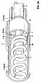
- Fig. 2A shows the internal structure of the electrode head 1, together with the first half-shell 1.1 of the head housing
- Fig. 2B shows the second half-shell 1.2 of the head housing, each in turn in perspective view.
- the above-mentioned sections 1a to 1e of the outer contour of the head housing in Fig. 2A and 2 B not indicated again.
- both half shells 1.1, 1.2 a (of course, also half-shelled) subdivision into three in the longitudinal direction have adjoining chamber segments 1.1A, 1.1B and 1.1C or 1.2A, 1.2B and 1.2C.
- the said chamber segments are separated by in principle circular segment-shaped partitions with central passage from each other, of which in Fig. 2A only the more distal partition 1.1D of the first half-shell 1.1, in Fig. 2B however, both partitions 1.2D and 1.2E can be seen.
- the half-shells 1.1, 1.2 are not identical, but different projections and recesses or attacks and centering both in the region of the distal flange and two of the three stepped cylindrical portions and finally the Have partitions. Among other things, this ensures that there are sufficiently large overlapping areas between the first and second half-shell in the wall of the head housing to ensure high mechanical stability and tightness of the rear portion of the head housing.
- Fig. 2A It can be seen how the helical coil 3, the distal chamber 1A of the electrode head 1 in the retracted state fills in its entire length and with its proximal end a plunger 5a a Fix istsschrauben-actuating shaft 5 encloses, on which they (which can not be seen here) cohesively is attached (such as by welding).
- the fixing screw actuating shaft 5 is surrounded by a sealing ring 7 and an X-ray contrast ring 9 such that the circumference of the chamber is largely filled.
- a contact sleeve 11 for electrical contacting of the (not shown here) conductor coil of the electrode line body with the plunger 5a and the helical screw 3 can be seen.
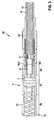
- Fig. 3 shows in a longitudinal sectional view of the distal end portion of a with the electrode head 1 behind Fig. 1 to 2B provided electrode line 10.
- the electrode line 10 comprises a (not shown here) outer lead body or outer tube, serving for contacting a ring electrode 13 and also not shown here outer conductor coil and disposed within an inner tube 15 inner conductor coil 17.
- fixing screw actuating shaft 5 is placed and at its end is also already mentioned above contact sleeve 11 is attached.
- the mechanical connection and at the same time sealing between the electrode head 1 and the line body of the line 10 distal from the ring electrode 13 is accomplished by an inner PTFE tube 19.1 and a substantially also tubular outer silicone connector 19.2. While the PTFE tube 19.1 lies within the proximal chamber 1C of the electrode head 1 and extends over a distal region of the inner conductor helix 17, the silicone connector 19.2 engages around a distal end portion of the ring electrode 13 as well as the outer wall of the proximal chamber 1C (FIG. or, based on the external view, the proximal cylinder portion 1d) of the electrode head 1 and connects them together.
- Fig. 3 still on the complete representation of the sealing ring 7, of which in Fig. 2A only a distal end portion is visible. It can be seen that the outer contour of the sealing ring 7 is stepped or chamfered several times.
- a hollow cylindrical medicament storage region 21 is shown, which serves (again in a manner known per se) for the storage and long-term continuous delivery of an anti-inflammatory steroid in the implanted state of the electrode line. If the half-shells are already firmly connected to the cylindrical electrode head 1, the medicament storage in the form of a hollow cylinder 21 in the distal region is pushed over and fastened.
- the electrode head 1 is preferably made of PEEK half-shells, but alternatively PU shells or housing parts can be manufactured from another polymer which can be used in implanted parts. Basically comes also the production of a biocompatible metal, such as titanium or a titanium alloy or stainless steel, into consideration, however, taking special design precautions to ensure the radiopacity of the screwed length of the helix and, if necessary. Special spring areas must be provided, which does not exist in the embodiment described above are.
Landscapes
- Health & Medical Sciences (AREA)
- Heart & Thoracic Surgery (AREA)
- Engineering & Computer Science (AREA)
- Life Sciences & Earth Sciences (AREA)
- General Health & Medical Sciences (AREA)
- Biomedical Technology (AREA)
- Nuclear Medicine, Radiotherapy & Molecular Imaging (AREA)
- Radiology & Medical Imaging (AREA)
- Veterinary Medicine (AREA)
- Animal Behavior & Ethology (AREA)
- Cardiology (AREA)
- Public Health (AREA)
- Vascular Medicine (AREA)
- Chemical & Material Sciences (AREA)
- Bioinformatics & Cheminformatics (AREA)
- Medicinal Chemistry (AREA)
- Electrotherapy Devices (AREA)
Claims (15)
- Tête d'électrode (1), pouvant être reliée de manière proximale avec un corps de ligne d'électrode (10) implantable, conçu de manière distale pour la fixation sur, ou dans, un organe creux ou un vaisseau, avec un boîtier de tête cylindrique allongé et présentant un axe longitudinal, où le boîtier de tête présente au moins deux parties de boîtier (1.1, 1.2) en forme de segments de corps de cylindre, qui sont solidement assemblées, caractérisée en ce que les parties de boîtier forment le corps de cylindre du boîtier de tête.
- Tête d'électrode (1) selon la revendication 1, où le boîtier de tête est accommodé dans son contour extérieur de deux parties de corps (1.1, 1.2) demi cylindriques avec un plan de séparation parallèle à l'axe longitudinal.
- Tête d'électrode (1) selon la revendication 1, ou 2, où les parties de boîtier (1.1, 1.2), notamment les parties de corps demi cylindriques, du boîtier de tête sont soudées ensemble (1f) ou collées.
- Tête d'électrode (1) selon l'une des revendications précédentes, où les parties de boîtier sont des parties de moule métallique, notamment des parties d'estampage de métal.
- Tête d'électrode (1) selon l'une des revendications 1 à 3, où les parties de boîtier (1.1, 1.2) sont des parties en matière plastique, notamment des parties moulées par injection en polyétheréthercétone PEEK.
- Tête d'électrode (1) selon l'une des revendications précédentes, où la tête d'électrode présente un diamètre extérieur dans une section proximale inférieur à celui dans une section se situant de manière distale par rapport à celle-ci.
- Tête d'électrode (1) selon l'une des revendications précédentes, avec une extrémité distale (1e) et/ou proximale ouverte(s).
- Tête d'électrode (1) selon l'une des revendications précédentes, qui présente une multitude de chambres (1A à 1c) délimitées par des morceaux de parois transversales avec un passage central.
- Tête d'électrode (1) selon l'une des revendications précédentes, avec une région de stockage de médicaments (21) dans une portion de la surface extérieure.
- Tête d'électrode (1) selon la revendication 9, où la région de stockage de médicaments (21) est de forme annulaire.
- Ligne d'électrode (10) avec un corps de ligne d'électrode allongé pliable et une tête d'électrode (1) selon l'une des revendications précédentes accommodée de manière distale sur le corps de ligne d'électrode.
- Ligne d'électrode (10) selon la revendication 11, où la tête d'électrode (1) est fixée sur le corps de ligne d'électrode au moyen d'au moins une pièce de tuyau de liaison (19.1, 19.2) élastique.
- Ligne d'électrode (10) selon la revendication 11, ou 12, avec un élément de fixation (3) actif, lequel est notamment logé dans une première chambre (1A) de la tête d'électrode (1) se situant de manière distale.
- Ligne d'électrode (10) selon la revendication 13, où l'élément de fixation est conçu sous la forme d'une hélice pouvant être mise en rotation et être déplacée.
- Ligne d'électrode (10) selon l'une des revendications 11 à 14, avec un anneau d'étanchéité (7) et/ou un anneau de contraste pour rayons X (9), qui est /sont notamment logé /logés dans au moins une deuxième chambre (IB) de la tête d'électrode (1), qui se situe de manière proximale par rapport à la première chambre.
Applications Claiming Priority (1)
| Application Number | Priority Date | Filing Date | Title |
|---|---|---|---|
| US201361910442P | 2013-12-02 | 2013-12-02 |
Publications (2)
| Publication Number | Publication Date |
|---|---|
| EP2878331A1 EP2878331A1 (fr) | 2015-06-03 |
| EP2878331B1 true EP2878331B1 (fr) | 2016-09-21 |
Family
ID=51893820
Family Applications (1)
| Application Number | Title | Priority Date | Filing Date |
|---|---|---|---|
| EP14190627.1A Active EP2878331B1 (fr) | 2013-12-02 | 2014-10-28 | Tête d'électrode avec une enveloppe présentant des parties en forme de segments d'une enveloppe de cylindre |
Country Status (2)
| Country | Link |
|---|---|
| US (1) | US20150151108A1 (fr) |
| EP (1) | EP2878331B1 (fr) |
Families Citing this family (3)
| Publication number | Priority date | Publication date | Assignee | Title |
|---|---|---|---|---|
| EP3320946A1 (fr) * | 2016-11-15 | 2018-05-16 | BIOTRONIK SE & Co. KG | Conduite implantable |
| DK3573700T3 (da) * | 2017-01-25 | 2022-04-04 | Epi Minder Pty Ltd | Elektrodeanordning til overvågning og/eller stimulering af aktivitet hos en person |
| CN109865203B (zh) * | 2018-12-28 | 2024-04-19 | 王澎 | 多功能起搏器手术连续测试标测连接线 |
Family Cites Families (8)
| Publication number | Priority date | Publication date | Assignee | Title |
|---|---|---|---|---|
| US5496360A (en) * | 1994-04-12 | 1996-03-05 | Ventritex, Inc. | Implantable cardiac electrode with rate controlled drug delivery |
| SE0101154D0 (sv) * | 2001-03-29 | 2001-03-29 | St Jude Medical | An electrically conductive lead and a method of producing such a lead |
| US20080114230A1 (en) * | 2006-11-14 | 2008-05-15 | Bruce Addis | Electrode support |
| US8744548B2 (en) * | 2009-06-10 | 2014-06-03 | Medtronic, Inc. | Lead apparatus |
| US8887387B2 (en) * | 2009-07-07 | 2014-11-18 | Boston Scientific Neuromodulation Corporation | Methods of manufacture of leads with a radially segmented electrode array |
| US8874232B2 (en) * | 2009-11-30 | 2014-10-28 | Boston Scientific Neuromodulation Corporation | Electrode array having concentric split ring electrodes and methods of making the same |
| US10131044B2 (en) * | 2010-07-30 | 2018-11-20 | Motion Pro, Inc. | Fork seal driver tool |
| US8583237B2 (en) * | 2010-09-13 | 2013-11-12 | Cranial Medical Systems, Inc. | Devices and methods for tissue modulation and monitoring |
-
2014
- 2014-10-22 US US14/520,859 patent/US20150151108A1/en not_active Abandoned
- 2014-10-28 EP EP14190627.1A patent/EP2878331B1/fr active Active
Also Published As
| Publication number | Publication date |
|---|---|
| US20150151108A1 (en) | 2015-06-04 |
| EP2878331A1 (fr) | 2015-06-03 |
Similar Documents
| Publication | Publication Date | Title |
|---|---|---|
| DE69632006T2 (de) | Führungsdrahteinheit | |
| DE2560406C2 (de) | Implantierbare Zuleitung mit verankerbarer Elektrode | |
| EP3294216B1 (fr) | Dispositif implantable pour améliorer ou supprimer une insuffisance valvulaire | |
| DE60015742T2 (de) | Medizinische elektrodenleitung | |
| EP2123323B1 (fr) | Fil d'électrode implantable | |
| DE69022084T2 (de) | Herzschrittmacherleiter. | |
| WO2019077401A2 (fr) | Procédé servant à fabriquer un tuyau flexible d'insertion d'un endoscope, et endoscope comprenant un tuyau flexible d'insertion | |
| EP3423148B1 (fr) | Électrode à gaine implantable | |
| DE102008008927A1 (de) | Elektrodenleitung und Anschlussstück für elektromedizinische Implantate | |
| EP1334745B1 (fr) | Fil de guidage et conducteur implantable | |
| EP3320946A1 (fr) | Conduite implantable | |
| EP2878331B1 (fr) | Tête d'électrode avec une enveloppe présentant des parties en forme de segments d'une enveloppe de cylindre | |
| EP2633883B1 (fr) | Cathéter à électrodes, notamment pour la thérapie cardiaque | |
| EP2667830B1 (fr) | Dispositif médical ayant une structure de treillis et un système de traitement à l'aide d'une telle structure de treillis | |
| EP2564889B1 (fr) | Aide à l'introduction d'un fil de guidage | |
| EP2676641A2 (fr) | Elément d'insertion et le dispositif d'insertion | |
| WO2021074371A1 (fr) | Élément de guidage conçu pour un système d'élargissement vasculaire commandable, et système d'élargissement vasculaire commandable | |
| EP3630266B1 (fr) | Adaptateur électro-médical, électrode électro-médicale et émetteur d'impulsions électro-médical | |
| DE102019104641A1 (de) | Zugkraftverstärkungsschlauch für eine implantierbare Elektrodenleitung oder einen Katheter, Elektrodenleitung mit einem Zugkraftverstärkungsschlauch und Katheter mit einem Zugkraftverstärkungsschlauch | |
| EP1685813A1 (fr) | Stent greffe | |
| EP2082778B1 (fr) | Electrode bipolaire | |
| DE102013113263A1 (de) | Medizinisches Instrument für intravaskuläre Eingriffe und Herstellungsverfahren | |
| EP2862594A1 (fr) | Fixation active et réversible d'électrodes CRT | |
| DE102022118531B4 (de) | Sondensystem für die endoluminale Unterdrucktherapie | |
| DE69216805T2 (de) | Endokardiumsonden mit klappbaren Widerhäckchen |
Legal Events
| Date | Code | Title | Description |
|---|---|---|---|
| PUAI | Public reference made under article 153(3) epc to a published international application that has entered the european phase |
Free format text: ORIGINAL CODE: 0009012 |
|
| 17P | Request for examination filed |
Effective date: 20141028 |
|
| AK | Designated contracting states |
Kind code of ref document: A1 Designated state(s): AL AT BE BG CH CY CZ DE DK EE ES FI FR GB GR HR HU IE IS IT LI LT LU LV MC MK MT NL NO PL PT RO RS SE SI SK SM TR |
|
| AX | Request for extension of the european patent |
Extension state: BA ME |
|
| R17P | Request for examination filed (corrected) |
Effective date: 20151202 |
|
| RBV | Designated contracting states (corrected) |
Designated state(s): AL AT BE BG CH CY CZ DE DK EE ES FI FR GB GR HR HU IE IS IT LI LT LU LV MC MK MT NL NO PL PT RO RS SE SI SK SM TR |
|
| GRAP | Despatch of communication of intention to grant a patent |
Free format text: ORIGINAL CODE: EPIDOSNIGR1 |
|
| INTG | Intention to grant announced |
Effective date: 20160614 |
|
| GRAS | Grant fee paid |
Free format text: ORIGINAL CODE: EPIDOSNIGR3 |
|
| GRAA | (expected) grant |
Free format text: ORIGINAL CODE: 0009210 |
|
| AK | Designated contracting states |
Kind code of ref document: B1 Designated state(s): AL AT BE BG CH CY CZ DE DK EE ES FI FR GB GR HR HU IE IS IT LI LT LU LV MC MK MT NL NO PL PT RO RS SE SI SK SM TR |
|
| REG | Reference to a national code |
Ref country code: GB Ref legal event code: FG4D Free format text: NOT ENGLISH |
|
| REG | Reference to a national code |
Ref country code: CH Ref legal event code: EP |
|
| REG | Reference to a national code |
Ref country code: AT Ref legal event code: REF Ref document number: 830563 Country of ref document: AT Kind code of ref document: T Effective date: 20161015 |
|
| REG | Reference to a national code |
Ref country code: IE Ref legal event code: FG4D Free format text: LANGUAGE OF EP DOCUMENT: GERMAN |
|
| REG | Reference to a national code |
Ref country code: DE Ref legal event code: R096 Ref document number: 502014001517 Country of ref document: DE |
|
| REG | Reference to a national code |
Ref country code: LT Ref legal event code: MG4D Ref country code: NL Ref legal event code: MP Effective date: 20160921 |
|
| PG25 | Lapsed in a contracting state [announced via postgrant information from national office to epo] |
Ref country code: LT Free format text: LAPSE BECAUSE OF FAILURE TO SUBMIT A TRANSLATION OF THE DESCRIPTION OR TO PAY THE FEE WITHIN THE PRESCRIBED TIME-LIMIT Effective date: 20160921 Ref country code: FI Free format text: LAPSE BECAUSE OF FAILURE TO SUBMIT A TRANSLATION OF THE DESCRIPTION OR TO PAY THE FEE WITHIN THE PRESCRIBED TIME-LIMIT Effective date: 20160921 Ref country code: RS Free format text: LAPSE BECAUSE OF FAILURE TO SUBMIT A TRANSLATION OF THE DESCRIPTION OR TO PAY THE FEE WITHIN THE PRESCRIBED TIME-LIMIT Effective date: 20160921 Ref country code: NO Free format text: LAPSE BECAUSE OF FAILURE TO SUBMIT A TRANSLATION OF THE DESCRIPTION OR TO PAY THE FEE WITHIN THE PRESCRIBED TIME-LIMIT Effective date: 20161221 |
|
| PG25 | Lapsed in a contracting state [announced via postgrant information from national office to epo] |
Ref country code: GR Free format text: LAPSE BECAUSE OF FAILURE TO SUBMIT A TRANSLATION OF THE DESCRIPTION OR TO PAY THE FEE WITHIN THE PRESCRIBED TIME-LIMIT Effective date: 20161222 Ref country code: LV Free format text: LAPSE BECAUSE OF FAILURE TO SUBMIT A TRANSLATION OF THE DESCRIPTION OR TO PAY THE FEE WITHIN THE PRESCRIBED TIME-LIMIT Effective date: 20160921 Ref country code: SE Free format text: LAPSE BECAUSE OF FAILURE TO SUBMIT A TRANSLATION OF THE DESCRIPTION OR TO PAY THE FEE WITHIN THE PRESCRIBED TIME-LIMIT Effective date: 20160921 Ref country code: BE Free format text: LAPSE BECAUSE OF NON-PAYMENT OF DUE FEES Effective date: 20161031 Ref country code: NL Free format text: LAPSE BECAUSE OF FAILURE TO SUBMIT A TRANSLATION OF THE DESCRIPTION OR TO PAY THE FEE WITHIN THE PRESCRIBED TIME-LIMIT Effective date: 20160921 |
|
| PG25 | Lapsed in a contracting state [announced via postgrant information from national office to epo] |
Ref country code: EE Free format text: LAPSE BECAUSE OF FAILURE TO SUBMIT A TRANSLATION OF THE DESCRIPTION OR TO PAY THE FEE WITHIN THE PRESCRIBED TIME-LIMIT Effective date: 20160921 Ref country code: RO Free format text: LAPSE BECAUSE OF FAILURE TO SUBMIT A TRANSLATION OF THE DESCRIPTION OR TO PAY THE FEE WITHIN THE PRESCRIBED TIME-LIMIT Effective date: 20160921 |
|
| PG25 | Lapsed in a contracting state [announced via postgrant information from national office to epo] |
Ref country code: BG Free format text: LAPSE BECAUSE OF FAILURE TO SUBMIT A TRANSLATION OF THE DESCRIPTION OR TO PAY THE FEE WITHIN THE PRESCRIBED TIME-LIMIT Effective date: 20161221 Ref country code: SK Free format text: LAPSE BECAUSE OF FAILURE TO SUBMIT A TRANSLATION OF THE DESCRIPTION OR TO PAY THE FEE WITHIN THE PRESCRIBED TIME-LIMIT Effective date: 20160921 Ref country code: PL Free format text: LAPSE BECAUSE OF FAILURE TO SUBMIT A TRANSLATION OF THE DESCRIPTION OR TO PAY THE FEE WITHIN THE PRESCRIBED TIME-LIMIT Effective date: 20160921 Ref country code: PT Free format text: LAPSE BECAUSE OF FAILURE TO SUBMIT A TRANSLATION OF THE DESCRIPTION OR TO PAY THE FEE WITHIN THE PRESCRIBED TIME-LIMIT Effective date: 20170123 Ref country code: SM Free format text: LAPSE BECAUSE OF FAILURE TO SUBMIT A TRANSLATION OF THE DESCRIPTION OR TO PAY THE FEE WITHIN THE PRESCRIBED TIME-LIMIT Effective date: 20160921 Ref country code: ES Free format text: LAPSE BECAUSE OF FAILURE TO SUBMIT A TRANSLATION OF THE DESCRIPTION OR TO PAY THE FEE WITHIN THE PRESCRIBED TIME-LIMIT Effective date: 20160921 Ref country code: CZ Free format text: LAPSE BECAUSE OF FAILURE TO SUBMIT A TRANSLATION OF THE DESCRIPTION OR TO PAY THE FEE WITHIN THE PRESCRIBED TIME-LIMIT Effective date: 20160921 Ref country code: IS Free format text: LAPSE BECAUSE OF FAILURE TO SUBMIT A TRANSLATION OF THE DESCRIPTION OR TO PAY THE FEE WITHIN THE PRESCRIBED TIME-LIMIT Effective date: 20170121 |
|
| REG | Reference to a national code |
Ref country code: DE Ref legal event code: R097 Ref document number: 502014001517 Country of ref document: DE |
|
| PG25 | Lapsed in a contracting state [announced via postgrant information from national office to epo] |
Ref country code: IT Free format text: LAPSE BECAUSE OF FAILURE TO SUBMIT A TRANSLATION OF THE DESCRIPTION OR TO PAY THE FEE WITHIN THE PRESCRIBED TIME-LIMIT Effective date: 20160921 |
|
| PLBE | No opposition filed within time limit |
Free format text: ORIGINAL CODE: 0009261 |
|
| REG | Reference to a national code |
Ref country code: FR Ref legal event code: ST Effective date: 20170630 |
|
| STAA | Information on the status of an ep patent application or granted ep patent |
Free format text: STATUS: NO OPPOSITION FILED WITHIN TIME LIMIT |
|
| PG25 | Lapsed in a contracting state [announced via postgrant information from national office to epo] |
Ref country code: DK Free format text: LAPSE BECAUSE OF FAILURE TO SUBMIT A TRANSLATION OF THE DESCRIPTION OR TO PAY THE FEE WITHIN THE PRESCRIBED TIME-LIMIT Effective date: 20160921 Ref country code: FR Free format text: LAPSE BECAUSE OF NON-PAYMENT OF DUE FEES Effective date: 20161121 |
|
| 26N | No opposition filed |
Effective date: 20170622 |
|
| PG25 | Lapsed in a contracting state [announced via postgrant information from national office to epo] |
Ref country code: LU Free format text: LAPSE BECAUSE OF NON-PAYMENT OF DUE FEES Effective date: 20161028 |
|
| PG25 | Lapsed in a contracting state [announced via postgrant information from national office to epo] |
Ref country code: SI Free format text: LAPSE BECAUSE OF FAILURE TO SUBMIT A TRANSLATION OF THE DESCRIPTION OR TO PAY THE FEE WITHIN THE PRESCRIBED TIME-LIMIT Effective date: 20160921 |
|
| REG | Reference to a national code |
Ref country code: BE Ref legal event code: MM Effective date: 20161031 |
|
| PG25 | Lapsed in a contracting state [announced via postgrant information from national office to epo] |
Ref country code: HU Free format text: LAPSE BECAUSE OF FAILURE TO SUBMIT A TRANSLATION OF THE DESCRIPTION OR TO PAY THE FEE WITHIN THE PRESCRIBED TIME-LIMIT; INVALID AB INITIO Effective date: 20141028 |
|
| PG25 | Lapsed in a contracting state [announced via postgrant information from national office to epo] |
Ref country code: HR Free format text: LAPSE BECAUSE OF FAILURE TO SUBMIT A TRANSLATION OF THE DESCRIPTION OR TO PAY THE FEE WITHIN THE PRESCRIBED TIME-LIMIT Effective date: 20160921 Ref country code: MT Free format text: LAPSE BECAUSE OF FAILURE TO SUBMIT A TRANSLATION OF THE DESCRIPTION OR TO PAY THE FEE WITHIN THE PRESCRIBED TIME-LIMIT Effective date: 20160921 Ref country code: MC Free format text: LAPSE BECAUSE OF FAILURE TO SUBMIT A TRANSLATION OF THE DESCRIPTION OR TO PAY THE FEE WITHIN THE PRESCRIBED TIME-LIMIT Effective date: 20160921 Ref country code: CY Free format text: LAPSE BECAUSE OF FAILURE TO SUBMIT A TRANSLATION OF THE DESCRIPTION OR TO PAY THE FEE WITHIN THE PRESCRIBED TIME-LIMIT Effective date: 20160921 Ref country code: MK Free format text: LAPSE BECAUSE OF FAILURE TO SUBMIT A TRANSLATION OF THE DESCRIPTION OR TO PAY THE FEE WITHIN THE PRESCRIBED TIME-LIMIT Effective date: 20160921 |
|
| PG25 | Lapsed in a contracting state [announced via postgrant information from national office to epo] |
Ref country code: AL Free format text: LAPSE BECAUSE OF FAILURE TO SUBMIT A TRANSLATION OF THE DESCRIPTION OR TO PAY THE FEE WITHIN THE PRESCRIBED TIME-LIMIT Effective date: 20160921 Ref country code: TR Free format text: LAPSE BECAUSE OF FAILURE TO SUBMIT A TRANSLATION OF THE DESCRIPTION OR TO PAY THE FEE WITHIN THE PRESCRIBED TIME-LIMIT Effective date: 20160921 |
|
| GBPC | Gb: european patent ceased through non-payment of renewal fee |
Effective date: 20181028 |
|
| PG25 | Lapsed in a contracting state [announced via postgrant information from national office to epo] |
Ref country code: GB Free format text: LAPSE BECAUSE OF NON-PAYMENT OF DUE FEES Effective date: 20181028 |
|
| REG | Reference to a national code |
Ref country code: AT Ref legal event code: MM01 Ref document number: 830563 Country of ref document: AT Kind code of ref document: T Effective date: 20191028 |
|
| PG25 | Lapsed in a contracting state [announced via postgrant information from national office to epo] |
Ref country code: AT Free format text: LAPSE BECAUSE OF NON-PAYMENT OF DUE FEES Effective date: 20191028 |
|
| PGFP | Annual fee paid to national office [announced via postgrant information from national office to epo] |
Ref country code: IE Payment date: 20221021 Year of fee payment: 9 Ref country code: DE Payment date: 20221025 Year of fee payment: 9 |
|
| PGFP | Annual fee paid to national office [announced via postgrant information from national office to epo] |
Ref country code: CH Payment date: 20221027 Year of fee payment: 9 |
|
| REG | Reference to a national code |
Ref country code: DE Ref legal event code: R119 Ref document number: 502014001517 Country of ref document: DE |
|
| REG | Reference to a national code |
Ref country code: CH Ref legal event code: PL |
|
| PG25 | Lapsed in a contracting state [announced via postgrant information from national office to epo] |
Ref country code: CH Free format text: LAPSE BECAUSE OF NON-PAYMENT OF DUE FEES Effective date: 20231031 |
|
| PG25 | Lapsed in a contracting state [announced via postgrant information from national office to epo] |
Ref country code: DE Free format text: LAPSE BECAUSE OF NON-PAYMENT OF DUE FEES Effective date: 20240501 Ref country code: CH Free format text: LAPSE BECAUSE OF NON-PAYMENT OF DUE FEES Effective date: 20231031 |
|
| PG25 | Lapsed in a contracting state [announced via postgrant information from national office to epo] |
Ref country code: IE Free format text: LAPSE BECAUSE OF NON-PAYMENT OF DUE FEES Effective date: 20231028 |
|
| PG25 | Lapsed in a contracting state [announced via postgrant information from national office to epo] |
Ref country code: IE Free format text: LAPSE BECAUSE OF NON-PAYMENT OF DUE FEES Effective date: 20231028 |