EP2878541A1 - Vortrieb für ein Kantenschutzmittel in einer Umreifungsvorrichtung - Google Patents
Vortrieb für ein Kantenschutzmittel in einer Umreifungsvorrichtung Download PDFInfo
- Publication number
- EP2878541A1 EP2878541A1 EP14194727.5A EP14194727A EP2878541A1 EP 2878541 A1 EP2878541 A1 EP 2878541A1 EP 14194727 A EP14194727 A EP 14194727A EP 2878541 A1 EP2878541 A1 EP 2878541A1
- Authority
- EP
- European Patent Office
- Prior art keywords
- edge protection
- gap
- protection means
- guide
- ausförderspalt
- Prior art date
- Legal status (The legal status is an assumption and is not a legal conclusion. Google has not performed a legal analysis and makes no representation as to the accuracy of the status listed.)
- Granted
Links
Images



Classifications
-
- B—PERFORMING OPERATIONS; TRANSPORTING
- B65—CONVEYING; PACKING; STORING; HANDLING THIN OR FILAMENTARY MATERIAL
- B65B—MACHINES, APPARATUS OR DEVICES FOR, OR METHODS OF, PACKAGING ARTICLES OR MATERIALS; UNPACKING
- B65B13/00—Bundling articles
- B65B13/18—Details of, or auxiliary devices used in, bundling machines or bundling tools
- B65B13/181—Details of, or auxiliary devices used in, bundling machines or bundling tools applying edge protecting members during bundling
-
- B—PERFORMING OPERATIONS; TRANSPORTING
- B65—CONVEYING; PACKING; STORING; HANDLING THIN OR FILAMENTARY MATERIAL
- B65B—MACHINES, APPARATUS OR DEVICES FOR, OR METHODS OF, PACKAGING ARTICLES OR MATERIALS; UNPACKING
- B65B41/00—Supplying or feeding container-forming sheets or wrapping material
- B65B41/02—Feeding sheets or wrapper blanks
- B65B41/10—Feeding sheets or wrapper blanks by rollers
-
- B—PERFORMING OPERATIONS; TRANSPORTING
- B65—CONVEYING; PACKING; STORING; HANDLING THIN OR FILAMENTARY MATERIAL
- B65B—MACHINES, APPARATUS OR DEVICES FOR, OR METHODS OF, PACKAGING ARTICLES OR MATERIALS; UNPACKING
- B65B43/00—Forming, feeding, opening or setting-up containers or receptacles in association with packaging
- B65B43/12—Feeding flexible bags or carton blanks in flat or collapsed state; Feeding flat bags connected to form a series or chain
- B65B43/14—Feeding individual bags or carton blanks from piles or magazines
- B65B43/22—Feeding individual bags or carton blanks from piles or magazines by rollers
- B65B43/225—Feeding individual bags or carton blanks from piles or magazines by rollers specially adapted for carton blanks
Definitions
- the invention relates to a propulsion for an edge protection agent in a packaging strapping device, in which an arrangement means the edge protection means prior to the strapping process on the package and the edge protection means is held after Umreifungsvorgang of a strap on the package, the edge protection means of a conveyor through a Aus cakesspalt the arrangement device is handed over.
- Devices for strapping packages usually have a so-called packing table, on which rests a package to be strapped in the device.
- a guide frame which surrounds the package and within which a strapping means, such as a thermoplastic band, is guided around the package starting from a tensioning and closing device.
- a strapping means such as a thermoplastic band
- the free end of the strap is held and the strap is tensioned by a partial withdrawal around the package.
- the strap is pulled out of the guide frame.
- the guide frame on its sides facing the package suitable retaining means, such as opening flaps, brush attachments or the like.
- the strapping material presses or cuts cardboard at the edges.
- edge protectants before the strapping process.
- These are usually plate-like cardboard, which are applied to the edges to be protected and are held by the strap on the package.
- the edge protection means are usually held in a magazine and passed from there via a drive to the assembly device, which positions the edge protection means on the package.
- the present invention proposes an improvement of DE 10 2012 016 659 in front. It has been shown that the cardboard used as edge protectants are sometimes subject to considerable differences in their quality. With perfect production of such cardboard edge protection means, these are almost completely flat, despite any embossed rabbet grooves, which cause a controlled buckling of the edge protection agent around the edge to be protected. However, fluctuating production conditions and edge protection agents from different supply sources as well as the storage conditions for edge protectants have a considerable influence on their quality, so that edge protectants are often curved or even twisted. This leads to an incorrect position transfer to the arrangement device, the holding means then can not absorb the edge protection means correctly.
- the trajectory of the edge protection means follows when a straight line is removed, which lies in alignment with the conveying direction.
- a curved or twisted, in particular helically twisted edge protection deviates from this ideal trajectory, which has the aforementioned problems in the transfer to the assembly device result.
- Object of the present invention is therefore to propose an improved propulsion for an edge protection agent in a strapping device.
- the invention is achieved by a drive with the features of claim 1, in particular with its characterizing features, according to which the Aus cakesspalt is followed by a control device in Aus clarification Gay by means of which the Aus removeides the edge protection means can be influenced.
- the essential advantage of the invention is to be seen in that the control device can influence the direction of movement and the movement path of the edge protection means.
- a curvature of the edge protection means directed, for example, transversely to the discharge movement a curved trajectory inevitably follows.
- the control device can the Edge protection agent when exiting the Aus cakespalt be imposed a counter-movement. If, for example, a curvature of movement curved to the left from the curvature of the edge protection means emerges from the discharge gap, the control device can impose a counter-movement directed to the right, so that both movements compensate each other over the movement path. In this way, it is ensured that the edge protection agent is transferred at the end of its Aus detail Gay in the correct position to the assembly device. In this case, the movement path - influenced by the control device and the curvature of the edge protection means - run quite curved. By compensating the control device is ensured in any case that a position-appropriate transfer takes place.
- control device has a guide gap through which the edge protection means is guided for transfer to the arrangement device.
- the guide gap is formed by two gap components which are arranged at an in particular constant distance from one another.
- the gap-forming gap components are movable transversely to the discharge movement, in particular that the gap components are pivotable transversely to the conveying direction.
- a particularly simple adjustment of the control device is ensured by the transverse movement of the gap components is induced by a control spindle.
- guide wheels, guide rollers and / or guide rollers are arranged in the guide gap of the gap components.
- the particular advantage of this is that the edge protection means rolls on the wheels, rollers or rollers minimized friction.
- rollers and / or rollers forming the Aus cakespalt form the control device itself.
- a drive according to the invention is provided overall with the reference numeral 10 and shown as a partial view of the Aus cakespalt.
- the propulsion system 10 comprises a base 11, which is part of a magazine, not shown, and on which two rolls 13 and 14 forming a discharge gap 12 are arranged.
- the first roller 13 is coupled to a drive belt 15 and is rotated by this drive belt 15 in rotation.
- the second roller 14 is designed without drive in the present embodiment. Friction increasing means in the form of rubber rings 16 are arranged on the rollers 13, 14.
- the drive belt 15 also serves as a conveying means, on which the edge protection means provided overall with the reference numeral 17 rests with a narrow side and is moved in the conveying direction to the rollers 13 and 14. Upon reaching the Aus thoroughlyspaltes 12, the rollers 13 and 14 engage the edge protection means 17 and take over the targeted Ausponent to an arrangement device, not shown.
- a control device is arranged downstream of the discharge gap 12 in the discharge movement.
- This carries the reference numeral 18. It initially comprises two guide gaps 19 forming a gap components 20 which are arranged at a constant distance from one another via a connecting leg 21.
- the split members 20, which are connected to one another via the connecting leg 21, are fastened in a pivotable manner to a mounting plate 23 via a bolt 22 or a comparatively acting fastening means, wherein the bolt 22 forms the pivot axis in geometric terms as well as objectively.
- a spindle drive in the form of a control spindle 24 comprises a spindle axis 25 with a spindle wheel 26 at its free end and is rotatably anchored in the mounting plate 23.
- a control member 27 is arranged vertically movable by rotation of the spindle axis 25.
- the control member 27 engages in a substantially vertically directed slot 28 of a control leg of a split member 20 a.
- the gap components 20 in the direction of a first maximum deflection (see Fig. 4 ) or in the direction of a second maximum deflection (see Fig. 5 ) pivots. Due to the change in position of the guide gap 19 forming gap components relative to the Ausdirspalt 12, the edge protection means 17 is deflected during its movement through the Aus decisspalt 12 and the guide gap 19 therethrough.
- an edge protection means 17 which has a curvature with a curvature axis which is directed vertically to the discharge direction and parallel to the Aus thoroughlyspalt 12, so this curvature induces a curved trajectory of the edge protection means 17 when leaving the Aus thoroughlyspaltes 12. Too strong deviation from the Idealtownsbahn, which is provided for the transfer to the arrangement device, has the consequence that the transfer to the arrangement device fails.
- the control device 18 makes it possible via a relative displacement of the guide gap 19 with respect to the Aus thoroughlyspalt 12 a Induce backlash. As a result of this countermovement, the edge protection means 17 reaches a position which is correct for the transfer upon reaching the arrangement device.
- the ideal trajectory as straight line between Aus thoroughlyspalt 12 and arrangement means and deviates imposed by the curvature of the edge protection means 17 trajectory, for example, to the right of the ideal trajectory, it can be induced via the control device 18, a counter-movement to the left compensates for the deviation from the ideal trajectory.
- Deviations in the embodiment of the invention are conceivable.
- the control device 18 is not pivoted about an axis, but is moved linearly.
- the movement of the control device 18 induced by the control spindle 24 can be accomplished via an engagement of gear and rack and a worm drive.
- a manual movement such as a motorized movement of the control spindle 24 is conceivable, wherein the manual movement is preferred.
Landscapes
- Engineering & Computer Science (AREA)
- Mechanical Engineering (AREA)
- Basic Packing Technique (AREA)
- Tyre Moulding (AREA)
Description
- Die Erfindung betrifft einen Vortrieb für ein Kantenschutzmittel in einer Umreifungsvorrichtung für Packstücke, in welcher eine Anordnungseinrichtung das Kantenschutzmittel vor dem Umreifungsvorgang am Packstück anordnet und das Kantenschutzmittel nach dem Umreifungsvorgang von einem Umreifungsmittel am Packstück gehalten ist, wobei das Kantenschutzmittel von einem Fördermittel durch einen Ausförderspalt an die Anordnungseinrichtung übergeben ist.
- Vorrichtungen zum Umreifen von Packstücken verfügen in der Regel über einen sogenannten Packtisch, auf welchem ein zu umreifendes Packstück in der Vorrichtung aufliegt. An dem Packtisch ist ein Führungsrahmen angeordnet, der das Packstück umgibt und innerhalb dessen ein Umreifungsmittel, wie beispielsweise ein thermoplastisches Band, ausgehend von einer Spann- und Verschlussvorrichtung um das Packstück geführt wird. Beim Wiedererreichen der Spann- und Verschlussvorrichtung wird das freie Ende des Umreifungsmittels gehalten und das Umreifungsmittel durch einen teilweisen Rückzug um das Packstück gespannt. Dabei wird das Umreifungsmittel aus dem Führungsrahmen herausgezogen. Um dies zu ermöglichen, weist der Führungsrahmen an seinen zum Packstück gewandten Seiten geeignete Rückhaltemittel auf, wie zu öffnende Klappen, Bürstenvorsätze oder Ähnliches. Beim Spannen des Umreifungsmittels um das Packstück übt dieses insbesondere an den Packstückkanten hohe Kräfte aus, die zur Beschädigung des Packstückes führen können. So ist es beispielsweise bekannt, dass das Umreifungsmittel Kartonagen an den Kanten eindrückt oder einschneidet. Je nach Packstückart und -güte ist dies unerwünscht. Um derartige Beschädigungen zu vermeiden, werden Packstücke vor dem Umreifungsvorgang mit Kantenschutzmitteln versehen. Hierbei handelt es sich in der Regel um plattenartige Kartonagen, die an den zu schützenden Kanten angelegt werden und vom Umreifungsmittel am Packstück gehalten sind.
- Die Kantenschutzmittel werden gewöhnlich in einem Magazin vorgehalten und von dort über einen Vortrieb an die Anordnungseinrichtung übergeben, die das Kantenschutzmittel am Packstück positioniert.
- Aus dem druckschriftlich nicht belegbaren Stand der Technik ist es bekannt, dass Entnahmewerkzeuge an einer der in Förderrichtung hinteren Schmalkanten des plattenartigen Kantenschutzmittels angreifen und dieses zur Anordnungseinrichtung hin schieben. Auch ist es bekannt, dass Bänder an einer der zur Anlage am Packstück vorgesehenen Hauptflächen des Kantenschutzmittels reibschlüssig anliegen und der Reibschluss bei Bewegung des Bandes ausreichend ist, um das Kantenschutzmittel in Richtung Anordnungseinrichtung zu fördern.
- Aus der bislang unveröffentlichten
DE 10 2012 016 659 , geht eine gattungsgemäße Vorrichtung hervor, die sich der vorgenannten Nachteile des Standes der Technik annimmt und einen verbesserten Vortrieb für ein Kantenschutzmittel in einer Umreifungsvorrichtung vorschlägt. - Ausgehend von diesem unveröffentlichten Stand der Technik schlägt die vorliegende Erfindung eine Verbesserung der
DE 10 2012 016 659 vor. Es hat sich nämlich gezeigt, dass die häufig als Kantenschutzmittel verwendeten Kartonagen in ihrer Güte teilweise erheblichen Unterschieden unterliegen. Bei einwandfreier Fertigung solcher Karton-Kantenschutzmittel sind diese fast vollständig eben, trotz eventuell eingeprägter Falznuten, die ein kontrolliertes Knicken des Kantenschutzmittels um die zu schützende Kante herum bewirken. Schwankende Fertigungsbedingungen und Kantenschutzmittel aus unterschiedlichen Lieferquellen sowie die Lagerbedingungen für Kantenschutzmittel haben jedoch erheblichen Einfluss auf deren Qualität, sodass Kantenschutzmittel häufig gewölbt oder gar in sich verdreht sind. Dies führt zu einer nicht lagegerechten Übergabe an die Anordnungseinrichtung, deren Haltemittel dann das Kantenschutzmittel nicht korrekt aufnehmen können. - Bei Ausförderung eines idealen Kantenschutzmittels zur Anordnungseinrichtung folgt die Bewegungsbahn des Kantenschutzmittels bei Ausförderung einer Geraden, die in einer Flucht mit der Förderrichtung liegt. Ein gewölbtes oder in sich verdrehtes, insbesondere schraubenartig verdrehtes Kantenschutzmittel weicht von dieser idealen Bewegungsbahn ab, was die vorgenannten Probleme bei der Übergabe an die Anordnungseinrichtung zur Folge hat.
- Aufgabe der vorliegenden Erfindung ist es deshalb, einen verbesserten Vortrieb für ein Kantenschutzmittel in einer Umreifungsvorrichtung vorzuschlagen.
- Gelöst wird die Erfindung von einem Vortrieb mit den Merkmalen des Anspruchs 1, insbesondere mit dessen kennzeichnenden Merkmalen, wonach dem Ausförderspalt in Ausförderbewegung eine Steuereinrichtung nachgeordnet ist, mittels derer die Ausförderrichtung des Kantenschutzmittels beeinflussbar ist.
- Der wesentliche Vorteil der Erfindung ist darin zu sehen, dass mit der Steuereinrichtung Einfluss auf die Bewegungsrichtung und Bewegungsbahn des Kantenschutzmittels genommen werden kann. Zwar wird bei einer beispielsweise quer zur Ausförderbewegung gerichteten Wölbung des Kantenschutzmittels zwangsläufig eine gekrümmte Bewegungsbahn folgen. Durch die Steuereinrichtung kann dem Kantenschutzmittel beim Austreten aus dem Ausförderspalt jedoch eine Gegenbewegung aufgezwungen werden. Folgt aus der Wölbung des Kantenschutzmittels beispielsweise eine nach links gekrümmte Bewegungsbahn nach Austreten aus dem Ausförderspalt, kann die Steuereinrichtung eine nach rechts gerichtete Gegenbewegung aufzwingen, sodass sich beide Bewegungen über den Bewegungsweg hinweg kompensieren. Auf diese Weise ist sichergestellt, dass das Kantenschutzmittel am Ende seiner Ausförderbewegung in korrekter Lage an die Anordnungseinrichtung übergeben wird. Dabei kann die Bewegungsbahn - beeinflusst durch die Steuereinrichtung sowie die Krümmung des Kantenschutzmittels - durchaus geschwungen verlaufen. Durch die Kompensation der Steuereinrichtung ist in jedem Falle gewährleistet, dass eine lagegerechte Übergabe stattfindet.
- Es ist daran gedacht, dass der Ausförderspalt von zwei Rollen und/oder Walzen gebildet ist, zwischen denen das Kantenschutzmittel zur Übergabe an die Anordnungseinrichtung hindurchgeführt ist.
- Eine besonders einfach gestaltete Steuereinrichtung kennzeichnet sich dadurch, dass die Steuereinrichtung einen Führungsspalt aufweist, durch welchen das Kantenschutzmittel zur Übergabe an die Anordnungseinrichtung hindurchgeführt ist.
- Es ist vorgesehen, dass der Führungsspalt von zwei in einem insbesondere konstanten Abstand voneinander angeordneten Spaltbauteilen gebildet ist.
- Um die Ausförderrichtung zu beeinflussen, ist vorgesehen, dass die spaltbildenden Spaltbauteile quer zur Ausförderbewegung beweglich sind, insbesondere dass die Spaltbauteile quer zur Förderrichtung schwenkbar sind.
- Eine besonders einfache Verstellung der Steuereinrichtung ist gewährleistet, indem die Querbewegung der Spaltbauteile durch eine Steuerspindel induziert ist.
- Um ein reibungsminimiertes Ausfördern des Kantenschutzmittels durch den Führungsspalt zu gewährleisten, ist vorgesehen, dass im Führungsspalt der Spaltbauteile Führungsräder, Führungsrollen und/oder Führungswalzen angeordnet sind. Der besondere Vorteil hierin liegt, dass das Kantenschutzmittel an den Rädern, Rollen bzw. Walzen reibungsminimiert abrollt.
- Es kann weiterhin vorgesehen sein, dass die den Ausförderspalt bildenden Rollen und/oder Walzen selbst die Steuereinrichtung bilden.
- Weitere Vorteile der Erfindung sowie ein besseres Verständnis folgen aus der nachfolgenden Beschreibung eines Ausführungsbeispiels. Es zeigen:
- Fig. 1:
- eine Teilansicht eines erfindungsgemäßen Vortriebs mit Kantenschutzmittel in perspektivischer Ansicht auf den von Walzen gebildeten Ausförderspalt,
- Fig. 2:
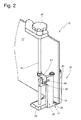
- die Darstellung gemäß
Fig. 1 mit Kantenschutzmittel unter Weglassen der den Ausförderspalt bildenden Walzen; - Fig. 3:
- die Darstellung gemäß
Fig. 1 ohne Kantenschutzmittel mit Steuereinrichtung in Neutralstellung; - Fig. 4:
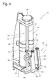
- die Darstellung gemäß
Fig. 1 mit Steuereinrichtung in einer ersten Steuerstellung; - Fig. 5:
- die Darstellung gemäß
Fig. 3 mit Steuereinrichtung in einer zweiten Steuerstellung. - In den Figuren ist ein erfindungsgemäßer Vortrieb insgesamt mit der Bezugsziffer 10 versehen und als Teilansicht auf den Ausförderspalt dargestellt.
- Der Vortrieb 10 umfasst eine Basis 11, die Teil eines nicht dargestellten Magazins ist und auf welcher zwei einen Ausförderspalt 12 bildende Walzen 13 und 14 angeordnet sind. Die ersten Walze 13 ist mit einem Treibriemen 15 gekoppelt und wird durch diesen Treibriemen 15 in Drehung versetzt. Die zweite Walze 14 ist im vorliegenden Ausführungsbeispiel antriebslos ausgeführt. Reibungserhöhende Mittel in Form von Gummiringen 16 sind auf den Walzen 13, 14 angeordnet.
- Der Treibriemen 15 dient darüber hinaus als Fördermittel, auf welchem das insgesamt mit der Bezugsziffer 17 versehene Kantenschutzmittel mit einer Schmalseite aufliegt und in Förderrichtung zu den Walzen 13 und 14 bewegt wird. Bei Erreichen des Ausförderspaltes 12 greifen die Walzen 13 und 14 das Kantenschutzmittel 17 an und übernehmen die zielgerichtete Ausförderung zu einer nicht dargestellten Anordnungseinrichtung.
- Zur Beeinflussung der Bewegungsbahn des Kantenschutzmittels 17 bzw. der Ausförderrichtung ist dem Ausförderspalt 12 eine Steuereinrichtung in Ausförderbewegung nachgeordnet. Diese trägt die Bezugsziffer 18. Sie umfasst zunächst zwei einen Führungsspalt 19 bildende Spaltbauteile 20, die in einem konstanten Abstand zueinander über einen Verbindungsschenkel 21 angeordnet sind. Die über den Verbindungsschenkel 21 miteinander verbundenen Spaltbauteile 20 sind über einen Schraubbolzen 22 oder ein vergleichbar wirkendes Befestigungsmittel an einer Montageplatte 23 schwenkbeweglich befestigt, wobei der Schraubbolzen 22 die Schwenkachse in geometrischer Hinsicht wie auch in gegenständlicher Hinsicht bildet.
- Ein Spindelantrieb in Form einer Steuerspindel 24 umfasst eine Spindelachse 25 mit einem Spindelrad 26 an ihrem freien Ende und ist drehbar in der Montageplatte 23 verankert.
- An der Spindelachse 25 ist ein Steuerglied 27 vertikal durch Rotation der Spindelachse 25 verfahrbar angeordnet. Das Steuerglied 27 greift in ein im Wesentlichen vertikal gerichtetes Langloch 28 eines Steuerschenkels eines Spaltbauteils 20 ein. Durch Drehen der Spindelachse 25 mittels des Spindelrades 26 und der dadurch induzierten Vertikalbewegung des Steuergliedes 27 drückt letzteres den Steuerschenkel 29 nach oben oder nach unten. Hierbei werden die Spaltbauteile 20 in Richtung einer ersten Maximalauslenkung (siehe
Fig. 4 ) bzw. in Richtung einer zweiten Maximalauslenkung (sieheFig. 5 ) verschwenkt. Durch die Lageänderung der den Führungsspalt 19 bildenden Spaltbauteile relativ zum Ausförderspalt 12 wird das Kantenschutzmittel 17 bei seiner Bewegung durch den Ausförderspalt 12 und den Führungsspalt 19 hindurch umgelenkt. - Wird ein Kantenschutzmittel 17 ausgefördert, welches eine Wölbung mit einer Wölbungsachse aufweist, die vertikal zur Ausförderrichtung und parallel zum Ausförderspalt 12 gerichtet ist, so induziert diese Wölbung eine gekrümmte Bewegungsbahn des Kantenschutzmittels 17 bei Verlassen des Ausförderspaltes 12. Eine zu starke Abweichung von der Idealbewegungsbahn, die für die Übergabe an die Anordnungseinrichtung vorgesehen ist, hat zur Folge, dass die Übergabe an die Anordnungseinrichtung misslingt.
- Die Steuereinrichtung 18 ermöglicht es über eine Relativverlagerung des Führungsspaltes 19 gegenüber dem Ausförderspalt 12 eine Gegenbewegung zu induzieren. Diese Gegenbewegung führt dazu, dass das Kantenschutzmittel 17 bei Erreichen der Anordnungseinrichtung eine für die Übergabe korrekte Lage erreicht.
- Stellt man sich die Ideal-Bewegungsbahn als Gerade zwischen Ausförderspalt 12 und Anordnungseinrichtung vor und weicht die von der Wölbung des Kantenschutzmittels 17 aufgezwungene Bewegungsbahn beispielsweise nach rechts von der Ideal-Bewegungsbahn ab, so kann über die Steuereinrichtung 18 eine Gegenbewegung nach links induziert werden, die das Abweichen von der Ideal-Bewegungsbahn kompensiert.
- Abweichungen in der Ausführungsart der Erfindung sind denkbar. Insbesondere ist es möglich, dass die Steuereinrichtung 18 nicht um eine Achse verschwenkt, sondern linear bewegt wird. Auch kann die durch die Steuerspindel 24 induzierte Bewegung der Steuereinrichtung 18 über einen Eingriff von Zahnrad und Zahnstange und einen Schneckenantrieb bewerkstelligt werden.
- Ein händisches Bewegen wie ein motorisches Bewegen der Steuerspindel 24 ist denkbar, wobei das händische Bewegen bevorzugt ist.
-
- 10
- Vortrieb
- 11
- Basis
- 12
- Ausförderspalt
- 13
- erste Walze
- 14
- zweite Walze
- 15
- Treibriemen
- 16
- Gummiring
- 17
- Kantenschutzmittel
- 18
- Steuereinrichtung
- 19
- Führungsspalt
- 20
- Spaltbauteile
- 21
- Verbindungsschenkel
- 22
- Schraubbolzen
- 23
- Montageplatte
- 24
- Steuerspindel
- 25
- Spindelachse
- 26
- Spindelrad
- 27
- Steuerglied
- 28
- Langloch
- 29
- Steuerschenkel
Claims (8)
- Vortrieb 10 für ein Kantenschutzmittel 17 in einer Umreifungsvorrichtung für Packstücke, in welcher eine Anordnungseinrichtung das Kantenschutzmittel 17 vor dem Umreifungsvorgang am Packstück anordnet und das Kantenschutzmittel 17 nach dem Umreifungsvorgang von einem Umreifungsmittel am Packstück gehalten ist, wobei das Kantenschutzmittel 17 von einem Fördermittel 15 durch einen Ausförderspalt 12 an die Anordnungseinrichtung übergeben ist, dadurch gekennzeichnet, dass dem Ausförderspalt 12 in Ausförderbewegung eine Steuereinrichtung 18 nachgeordnet ist, mittels derer die Ausförderrichtung des Kantenschutzmittels 17 beeinflussbar ist.
- Vortrieb nach Anspruch 1, dadurch gekennzeichnet, dass der Ausförderspalt 12 von zwei Rollen und/oder Walzen 13/14 gebildet ist, zwischen denen das Kantenschutzmittel 17 zur Übergabe an die Anordnungseinrichtung hindurchgeführt ist.
- Vortrieb nach Anspruch 1 oder 2, dadurch gekennzeichnet, dass die Steuereinrichtung 18 einen Führungsspalt 19 aufweist, durch welchen das Kantenschutzmittel 17 zur Übergabe an die Anordnungseinrichtung hindurchgeführt ist.
- Vortrieb nach Anspruch 3, dadurch gekennzeichnet, dass der Führungsspalt 19 von zwei in einem insbesondere konstanten Abstand voneinander angeordneten Spaltbauteilen 20 gebildet ist.
- Vortrieb nach Anspruch 3 oder 4, dadurch gekennzeichnet, dass die spaltbildenden Spaltbauteile 20 quer zur Ausförderbewegung beweglich sind.
- Vortrieb nach Anspruch 5, dadurch gekennzeichnet, dass die Spaltbauteile 20 quer zur Förderrichtung schwenkbar sind.
- Vortrieb nach Anspruch 5 oder 6, dadurch gekennzeichnet, dass die Querbewegung der Spaltbauteile 20 durch eine Steuerspindel 24 induziert ist.
- Vortrieb nach einem der Ansprüche 3 bis 7, dadurch gekennzeichnet, dass im Führungsspalt 19 der Spaltbauteile 20 Führungsräder, Führungsrollen und/oder Führungswalzen angeordnet sind.
Applications Claiming Priority (1)
| Application Number | Priority Date | Filing Date | Title |
|---|---|---|---|
| DE102013019891.7A DE102013019891A1 (de) | 2013-11-28 | 2013-11-28 | Vortrieb für ein Kantenschutzmittel in einer Umreifungsvorrichtung |
Publications (2)
| Publication Number | Publication Date |
|---|---|
| EP2878541A1 true EP2878541A1 (de) | 2015-06-03 |
| EP2878541B1 EP2878541B1 (de) | 2016-04-13 |
Family
ID=52016417
Family Applications (1)
| Application Number | Title | Priority Date | Filing Date |
|---|---|---|---|
| EP14194727.5A Not-in-force EP2878541B1 (de) | 2013-11-28 | 2014-11-25 | Vortrieb für ein Kantenschutzmittel in einer Umreifungsvorrichtung |
Country Status (3)
| Country | Link |
|---|---|
| EP (1) | EP2878541B1 (de) |
| DE (1) | DE102013019891A1 (de) |
| ES (1) | ES2582571T3 (de) |
Families Citing this family (5)
| Publication number | Priority date | Publication date | Assignee | Title |
|---|---|---|---|---|
| DE102015113350A1 (de) | 2015-08-13 | 2017-02-16 | Signode Industrial Group Llc | Umreifungsvorrichtung für Packstücke und Verfahren zum Umreifen |
| CN108720062B (zh) * | 2018-06-13 | 2020-12-15 | 黑龙江省农业机械工程科学研究院 | 一种拉伸膜供膜装置 |
| DE102019107702B3 (de) | 2019-03-26 | 2020-05-28 | Signode Industrial Group Llc | Verfahren zur Anordnung eines Kantenschutzmittels an einem Packstück in einer Vorrichtung zum Umreifen von Packstücken sowie Vorrichtung zum Umreifen von Packstücken |
| DE102019117949B4 (de) | 2019-07-03 | 2021-05-20 | Signode Industrial Group Llc | Umreifungsvorrichtung |
| US11801954B2 (en) | 2019-08-14 | 2023-10-31 | Signode Industrial Group Llc | Strapping machine with improved edge-protector-positioner |
Citations (4)
| Publication number | Priority date | Publication date | Assignee | Title |
|---|---|---|---|---|
| WO1996023610A1 (en) * | 1995-01-30 | 1996-08-08 | SSAB Tunnplåt AB | A machine and a method for applying edge protectors on coils |
| US5899046A (en) * | 1997-09-17 | 1999-05-04 | Hughes; Barry T. | Edge protector for masonry products and a system for its application |
| DE202012008064U1 (de) * | 2012-08-24 | 2013-11-25 | Itw Packaging Systems Group Gmbh | Vortrieb für ein Kantenschutzmittel in einer Umreifungsvorrichtung |
| DE102012016659A1 (de) | 2012-08-24 | 2014-02-27 | Itw Packaging Systems Group Gmbh | Vortrieb für ein Kantenschutzmittel in einer Umreifungsvorrichtung |
Family Cites Families (5)
| Publication number | Priority date | Publication date | Assignee | Title |
|---|---|---|---|---|
| US4587791A (en) * | 1984-12-24 | 1986-05-13 | United States Steel Corporation | Edge protector positioning apparatus |
| JPH05338899A (ja) * | 1992-06-08 | 1993-12-21 | Ricoh Co Ltd | 排紙装置 |
| JP2578504Y2 (ja) | 1992-10-20 | 1998-08-13 | アンリツ株式会社 | 紙葉搬送装置 |
| JP2002193525A (ja) * | 2000-12-26 | 2002-07-10 | Fuji Photo Film Co Ltd | カラー感熱プリンタ |
| JP5287182B2 (ja) * | 2008-11-28 | 2013-09-11 | 株式会社リコー | 用紙後処理装置及び画像形成装置 |
-
2013
- 2013-11-28 DE DE102013019891.7A patent/DE102013019891A1/de not_active Withdrawn
-
2014
- 2014-11-25 EP EP14194727.5A patent/EP2878541B1/de not_active Not-in-force
- 2014-11-25 ES ES14194727.5T patent/ES2582571T3/es active Active
Patent Citations (4)
| Publication number | Priority date | Publication date | Assignee | Title |
|---|---|---|---|---|
| WO1996023610A1 (en) * | 1995-01-30 | 1996-08-08 | SSAB Tunnplåt AB | A machine and a method for applying edge protectors on coils |
| US5899046A (en) * | 1997-09-17 | 1999-05-04 | Hughes; Barry T. | Edge protector for masonry products and a system for its application |
| DE202012008064U1 (de) * | 2012-08-24 | 2013-11-25 | Itw Packaging Systems Group Gmbh | Vortrieb für ein Kantenschutzmittel in einer Umreifungsvorrichtung |
| DE102012016659A1 (de) | 2012-08-24 | 2014-02-27 | Itw Packaging Systems Group Gmbh | Vortrieb für ein Kantenschutzmittel in einer Umreifungsvorrichtung |
Also Published As
| Publication number | Publication date |
|---|---|
| ES2582571T3 (es) | 2016-09-13 |
| EP2878541B1 (de) | 2016-04-13 |
| DE102013019891A1 (de) | 2015-05-28 |
Similar Documents
| Publication | Publication Date | Title |
|---|---|---|
| EP2700578B1 (de) | Umreifungsvorrichtung für Packstücke | |
| EP2878541B1 (de) | Vortrieb für ein Kantenschutzmittel in einer Umreifungsvorrichtung | |
| DE69207837T2 (de) | Spannvorrichtung zur Halterung von Rollen durch Druckbefestigung bei Schneidmaschinen zur Herstellung von Toilettenpapier und dergleichen | |
| DE202018100599U1 (de) | Bandförderer, insbesondere Wägebandförderer | |
| DE112015003768B4 (de) | Gekrümmte Bandförder-Vorrichtung | |
| DE1611838B2 (de) | Vorrichtung zum Herstellen einer Packung aus einer Gruppe von Artikeln, wie Flaschen u.dgl | |
| EP3433193A1 (de) | Anschlagmodul zum positionsgenauen anhalten eines gegenstands | |
| DE3506947A1 (de) | Schlauch-bandfoerderer | |
| DE10301178A1 (de) | Vorrichtung zum Ausrichten und Verteilen | |
| DE102012009897B4 (de) | Transportsystem | |
| EP3081517B1 (de) | Vorrichtung zum führen und fördern von draht- oder strangförmigen produkten | |
| EP1541470A1 (de) | Vorrichtung zum Längsumreifen eines Packstücks wie insbesondere eines Stapels von Zeitungen, Magazinen od.dgl. | |
| EP3336019B1 (de) | Justiereinrichtung | |
| DE69904892T2 (de) | Maschine zum Verpacken von Artikeln in Schachteln | |
| EP3033217B1 (de) | Umlenkvorrichtung für eine kette aus spannkluppen mit laufrollen zum transport einer bewegten materialbahn | |
| EP1050471A2 (de) | Faltschachtelförderer für eine Verpackungsmaschine | |
| DE202013010665U1 (de) | Vortrieb für ein Kantenschutzmittel in einer Umreifungsvorrichtung | |
| DE2644892C3 (de) | Maschine zum Verpacken von Kaugummistreifen | |
| DE1635893C3 (de) | Zwangsläufiger Garnzubnnger fur Strickmaschinen | |
| DE202012008064U1 (de) | Vortrieb für ein Kantenschutzmittel in einer Umreifungsvorrichtung | |
| EP3456668B1 (de) | Transporteinrichtung für faltschachtelzuschnitte | |
| DE3109427C2 (de) | ||
| DE69422626T2 (de) | Zuführvorrichtung für schneidvorrichtung | |
| DE19829176A1 (de) | Einrichtung an einer Verpackungsmaschine | |
| DE102013019400A1 (de) | Taschenfalzstation mit Abstützelement für Falztasche |
Legal Events
| Date | Code | Title | Description |
|---|---|---|---|
| PUAI | Public reference made under article 153(3) epc to a published international application that has entered the european phase |
Free format text: ORIGINAL CODE: 0009012 |
|
| 17P | Request for examination filed |
Effective date: 20141125 |
|
| AK | Designated contracting states |
Kind code of ref document: A1 Designated state(s): AL AT BE BG CH CY CZ DE DK EE ES FI FR GB GR HR HU IE IS IT LI LT LU LV MC MK MT NL NO PL PT RO RS SE SI SK SM TR |
|
| AX | Request for extension of the european patent |
Extension state: BA ME |
|
| R17P | Request for examination filed (corrected) |
Effective date: 20150825 |
|
| RBV | Designated contracting states (corrected) |
Designated state(s): AL AT BE BG CH CY CZ DE DK EE ES FI FR GB GR HR HU IE IS IT LI LT LU LV MC MK MT NL NO PL PT RO RS SE SI SK SM TR |
|
| GRAP | Despatch of communication of intention to grant a patent |
Free format text: ORIGINAL CODE: EPIDOSNIGR1 |
|
| INTG | Intention to grant announced |
Effective date: 20151221 |
|
| GRAS | Grant fee paid |
Free format text: ORIGINAL CODE: EPIDOSNIGR3 |
|
| GRAA | (expected) grant |
Free format text: ORIGINAL CODE: 0009210 |
|
| AK | Designated contracting states |
Kind code of ref document: B1 Designated state(s): AL AT BE BG CH CY CZ DE DK EE ES FI FR GB GR HR HU IE IS IT LI LT LU LV MC MK MT NL NO PL PT RO RS SE SI SK SM TR |
|
| REG | Reference to a national code |
Ref country code: GB Ref legal event code: FG4D Free format text: NOT ENGLISH |
|
| REG | Reference to a national code |
Ref country code: AT Ref legal event code: REF Ref document number: 789829 Country of ref document: AT Kind code of ref document: T Effective date: 20160415 Ref country code: CH Ref legal event code: EP |
|
| REG | Reference to a national code |
Ref country code: IE Ref legal event code: FG4D Free format text: LANGUAGE OF EP DOCUMENT: GERMAN |
|
| REG | Reference to a national code |
Ref country code: DE Ref legal event code: R096 Ref document number: 502014000614 Country of ref document: DE |
|
| REG | Reference to a national code |
Ref country code: LT Ref legal event code: MG4D |
|
| REG | Reference to a national code |
Ref country code: ES Ref legal event code: FG2A Ref document number: 2582571 Country of ref document: ES Kind code of ref document: T3 Effective date: 20160913 |
|
| REG | Reference to a national code |
Ref country code: NL Ref legal event code: MP Effective date: 20160413 |
|
| PG25 | Lapsed in a contracting state [announced via postgrant information from national office to epo] |
Ref country code: FI Free format text: LAPSE BECAUSE OF FAILURE TO SUBMIT A TRANSLATION OF THE DESCRIPTION OR TO PAY THE FEE WITHIN THE PRESCRIBED TIME-LIMIT Effective date: 20160413 Ref country code: NL Free format text: LAPSE BECAUSE OF FAILURE TO SUBMIT A TRANSLATION OF THE DESCRIPTION OR TO PAY THE FEE WITHIN THE PRESCRIBED TIME-LIMIT Effective date: 20160413 Ref country code: PL Free format text: LAPSE BECAUSE OF FAILURE TO SUBMIT A TRANSLATION OF THE DESCRIPTION OR TO PAY THE FEE WITHIN THE PRESCRIBED TIME-LIMIT Effective date: 20160413 Ref country code: NO Free format text: LAPSE BECAUSE OF FAILURE TO SUBMIT A TRANSLATION OF THE DESCRIPTION OR TO PAY THE FEE WITHIN THE PRESCRIBED TIME-LIMIT Effective date: 20160713 Ref country code: LT Free format text: LAPSE BECAUSE OF FAILURE TO SUBMIT A TRANSLATION OF THE DESCRIPTION OR TO PAY THE FEE WITHIN THE PRESCRIBED TIME-LIMIT Effective date: 20160413 |
|
| REG | Reference to a national code |
Ref country code: FR Ref legal event code: PLFP Year of fee payment: 3 |
|
| PG25 | Lapsed in a contracting state [announced via postgrant information from national office to epo] |
Ref country code: RS Free format text: LAPSE BECAUSE OF FAILURE TO SUBMIT A TRANSLATION OF THE DESCRIPTION OR TO PAY THE FEE WITHIN THE PRESCRIBED TIME-LIMIT Effective date: 20160413 Ref country code: GR Free format text: LAPSE BECAUSE OF FAILURE TO SUBMIT A TRANSLATION OF THE DESCRIPTION OR TO PAY THE FEE WITHIN THE PRESCRIBED TIME-LIMIT Effective date: 20160714 Ref country code: SE Free format text: LAPSE BECAUSE OF FAILURE TO SUBMIT A TRANSLATION OF THE DESCRIPTION OR TO PAY THE FEE WITHIN THE PRESCRIBED TIME-LIMIT Effective date: 20160413 Ref country code: HR Free format text: LAPSE BECAUSE OF FAILURE TO SUBMIT A TRANSLATION OF THE DESCRIPTION OR TO PAY THE FEE WITHIN THE PRESCRIBED TIME-LIMIT Effective date: 20160413 Ref country code: LV Free format text: LAPSE BECAUSE OF FAILURE TO SUBMIT A TRANSLATION OF THE DESCRIPTION OR TO PAY THE FEE WITHIN THE PRESCRIBED TIME-LIMIT Effective date: 20160413 Ref country code: PT Free format text: LAPSE BECAUSE OF FAILURE TO SUBMIT A TRANSLATION OF THE DESCRIPTION OR TO PAY THE FEE WITHIN THE PRESCRIBED TIME-LIMIT Effective date: 20160816 |
|
| REG | Reference to a national code |
Ref country code: DE Ref legal event code: R097 Ref document number: 502014000614 Country of ref document: DE |
|
| PG25 | Lapsed in a contracting state [announced via postgrant information from national office to epo] |
Ref country code: EE Free format text: LAPSE BECAUSE OF FAILURE TO SUBMIT A TRANSLATION OF THE DESCRIPTION OR TO PAY THE FEE WITHIN THE PRESCRIBED TIME-LIMIT Effective date: 20160413 Ref country code: SK Free format text: LAPSE BECAUSE OF FAILURE TO SUBMIT A TRANSLATION OF THE DESCRIPTION OR TO PAY THE FEE WITHIN THE PRESCRIBED TIME-LIMIT Effective date: 20160413 Ref country code: RO Free format text: LAPSE BECAUSE OF FAILURE TO SUBMIT A TRANSLATION OF THE DESCRIPTION OR TO PAY THE FEE WITHIN THE PRESCRIBED TIME-LIMIT Effective date: 20160413 Ref country code: DK Free format text: LAPSE BECAUSE OF FAILURE TO SUBMIT A TRANSLATION OF THE DESCRIPTION OR TO PAY THE FEE WITHIN THE PRESCRIBED TIME-LIMIT Effective date: 20160413 Ref country code: CZ Free format text: LAPSE BECAUSE OF FAILURE TO SUBMIT A TRANSLATION OF THE DESCRIPTION OR TO PAY THE FEE WITHIN THE PRESCRIBED TIME-LIMIT Effective date: 20160413 |
|
| PLBE | No opposition filed within time limit |
Free format text: ORIGINAL CODE: 0009261 |
|
| STAA | Information on the status of an ep patent application or granted ep patent |
Free format text: STATUS: NO OPPOSITION FILED WITHIN TIME LIMIT |
|
| PG25 | Lapsed in a contracting state [announced via postgrant information from national office to epo] |
Ref country code: BE Free format text: LAPSE BECAUSE OF NON-PAYMENT OF DUE FEES Effective date: 20161130 Ref country code: SM Free format text: LAPSE BECAUSE OF FAILURE TO SUBMIT A TRANSLATION OF THE DESCRIPTION OR TO PAY THE FEE WITHIN THE PRESCRIBED TIME-LIMIT Effective date: 20160413 |
|
| 26N | No opposition filed |
Effective date: 20170116 |
|
| PG25 | Lapsed in a contracting state [announced via postgrant information from national office to epo] |
Ref country code: SI Free format text: LAPSE BECAUSE OF FAILURE TO SUBMIT A TRANSLATION OF THE DESCRIPTION OR TO PAY THE FEE WITHIN THE PRESCRIBED TIME-LIMIT Effective date: 20160413 |
|
| REG | Reference to a national code |
Ref country code: IE Ref legal event code: MM4A |
|
| PG25 | Lapsed in a contracting state [announced via postgrant information from national office to epo] |
Ref country code: LU Free format text: LAPSE BECAUSE OF NON-PAYMENT OF DUE FEES Effective date: 20161130 |
|
| REG | Reference to a national code |
Ref country code: FR Ref legal event code: PLFP Year of fee payment: 4 |
|
| PG25 | Lapsed in a contracting state [announced via postgrant information from national office to epo] |
Ref country code: IE Free format text: LAPSE BECAUSE OF NON-PAYMENT OF DUE FEES Effective date: 20161125 |
|
| REG | Reference to a national code |
Ref country code: BE Ref legal event code: MM Effective date: 20161130 |
|
| PG25 | Lapsed in a contracting state [announced via postgrant information from national office to epo] |
Ref country code: HU Free format text: LAPSE BECAUSE OF FAILURE TO SUBMIT A TRANSLATION OF THE DESCRIPTION OR TO PAY THE FEE WITHIN THE PRESCRIBED TIME-LIMIT; INVALID AB INITIO Effective date: 20141125 |
|
| PG25 | Lapsed in a contracting state [announced via postgrant information from national office to epo] |
Ref country code: MC Free format text: LAPSE BECAUSE OF FAILURE TO SUBMIT A TRANSLATION OF THE DESCRIPTION OR TO PAY THE FEE WITHIN THE PRESCRIBED TIME-LIMIT Effective date: 20160413 Ref country code: IS Free format text: LAPSE BECAUSE OF FAILURE TO SUBMIT A TRANSLATION OF THE DESCRIPTION OR TO PAY THE FEE WITHIN THE PRESCRIBED TIME-LIMIT Effective date: 20160413 Ref country code: CY Free format text: LAPSE BECAUSE OF FAILURE TO SUBMIT A TRANSLATION OF THE DESCRIPTION OR TO PAY THE FEE WITHIN THE PRESCRIBED TIME-LIMIT Effective date: 20160413 Ref country code: MK Free format text: LAPSE BECAUSE OF FAILURE TO SUBMIT A TRANSLATION OF THE DESCRIPTION OR TO PAY THE FEE WITHIN THE PRESCRIBED TIME-LIMIT Effective date: 20160413 |
|
| PG25 | Lapsed in a contracting state [announced via postgrant information from national office to epo] |
Ref country code: CH Free format text: LAPSE BECAUSE OF NON-PAYMENT OF DUE FEES Effective date: 20171130 Ref country code: LI Free format text: LAPSE BECAUSE OF NON-PAYMENT OF DUE FEES Effective date: 20171130 Ref country code: BG Free format text: LAPSE BECAUSE OF FAILURE TO SUBMIT A TRANSLATION OF THE DESCRIPTION OR TO PAY THE FEE WITHIN THE PRESCRIBED TIME-LIMIT Effective date: 20160413 |
|
| PG25 | Lapsed in a contracting state [announced via postgrant information from national office to epo] |
Ref country code: MT Free format text: LAPSE BECAUSE OF FAILURE TO SUBMIT A TRANSLATION OF THE DESCRIPTION OR TO PAY THE FEE WITHIN THE PRESCRIBED TIME-LIMIT Effective date: 20160413 |
|
| PG25 | Lapsed in a contracting state [announced via postgrant information from national office to epo] |
Ref country code: AL Free format text: LAPSE BECAUSE OF FAILURE TO SUBMIT A TRANSLATION OF THE DESCRIPTION OR TO PAY THE FEE WITHIN THE PRESCRIBED TIME-LIMIT Effective date: 20160413 Ref country code: TR Free format text: LAPSE BECAUSE OF FAILURE TO SUBMIT A TRANSLATION OF THE DESCRIPTION OR TO PAY THE FEE WITHIN THE PRESCRIBED TIME-LIMIT Effective date: 20160413 |
|
| REG | Reference to a national code |
Ref country code: AT Ref legal event code: MM01 Ref document number: 789829 Country of ref document: AT Kind code of ref document: T Effective date: 20191125 |
|
| PG25 | Lapsed in a contracting state [announced via postgrant information from national office to epo] |
Ref country code: AT Free format text: LAPSE BECAUSE OF NON-PAYMENT OF DUE FEES Effective date: 20191125 |
|
| PGFP | Annual fee paid to national office [announced via postgrant information from national office to epo] |
Ref country code: ES Payment date: 20201201 Year of fee payment: 7 Ref country code: GB Payment date: 20201127 Year of fee payment: 7 Ref country code: FR Payment date: 20201125 Year of fee payment: 7 Ref country code: IT Payment date: 20201123 Year of fee payment: 7 |
|
| GBPC | Gb: european patent ceased through non-payment of renewal fee |
Effective date: 20211125 |
|
| PG25 | Lapsed in a contracting state [announced via postgrant information from national office to epo] |
Ref country code: GB Free format text: LAPSE BECAUSE OF NON-PAYMENT OF DUE FEES Effective date: 20211125 |
|
| PG25 | Lapsed in a contracting state [announced via postgrant information from national office to epo] |
Ref country code: FR Free format text: LAPSE BECAUSE OF NON-PAYMENT OF DUE FEES Effective date: 20211130 |
|
| PG25 | Lapsed in a contracting state [announced via postgrant information from national office to epo] |
Ref country code: IT Free format text: LAPSE BECAUSE OF NON-PAYMENT OF DUE FEES Effective date: 20211125 |
|
| REG | Reference to a national code |
Ref country code: ES Ref legal event code: FD2A Effective date: 20230220 |
|
| PG25 | Lapsed in a contracting state [announced via postgrant information from national office to epo] |
Ref country code: ES Free format text: LAPSE BECAUSE OF NON-PAYMENT OF DUE FEES Effective date: 20211126 |
|
| PGFP | Annual fee paid to national office [announced via postgrant information from national office to epo] |
Ref country code: DE Payment date: 20231129 Year of fee payment: 10 |
|
| REG | Reference to a national code |
Ref country code: DE Ref legal event code: R119 Ref document number: 502014000614 Country of ref document: DE |
|
| PG25 | Lapsed in a contracting state [announced via postgrant information from national office to epo] |
Ref country code: DE Free format text: LAPSE BECAUSE OF NON-PAYMENT OF DUE FEES Effective date: 20250603 |