EP2878544A1 - Procédé et dispositif de contrôle des collages entre des articles d'une gerbe - Google Patents
Procédé et dispositif de contrôle des collages entre des articles d'une gerbe Download PDFInfo
- Publication number
- EP2878544A1 EP2878544A1 EP13195347.3A EP13195347A EP2878544A1 EP 2878544 A1 EP2878544 A1 EP 2878544A1 EP 13195347 A EP13195347 A EP 13195347A EP 2878544 A1 EP2878544 A1 EP 2878544A1
- Authority
- EP
- European Patent Office
- Prior art keywords
- articles
- container
- article
- bonds
- individual
- Prior art date
- Legal status (The legal status is an assumption and is not a legal conclusion. Google has not performed a legal analysis and makes no representation as to the accuracy of the status listed.)
- Granted
Links
Images




Classifications
-
- B—PERFORMING OPERATIONS; TRANSPORTING
- B65—CONVEYING; PACKING; STORING; HANDLING THIN OR FILAMENTARY MATERIAL
- B65D—CONTAINERS FOR STORAGE OR TRANSPORT OF ARTICLES OR MATERIALS, e.g. BAGS, BARRELS, BOTTLES, BOXES, CANS, CARTONS, CRATES, DRUMS, JARS, TANKS, HOPPERS, FORWARDING CONTAINERS; ACCESSORIES, CLOSURES, OR FITTINGS THEREFOR; PACKAGING ELEMENTS; PACKAGES
- B65D21/00—Nestable, stackable or joinable containers; Containers of variable capacity
- B65D21/02—Containers specially shaped, or provided with fittings or attachments, to facilitate nesting, stacking, or joining together
- B65D21/0201—Containers specially shaped, or provided with fittings or attachments, to facilitate nesting, stacking, or joining together stackable or joined together side-by-side
- B65D21/0205—Containers specially shaped, or provided with fittings or attachments, to facilitate nesting, stacking, or joining together stackable or joined together side-by-side joined together by bonding, adhesive or the like
-
- B—PERFORMING OPERATIONS; TRANSPORTING
- B65—CONVEYING; PACKING; STORING; HANDLING THIN OR FILAMENTARY MATERIAL
- B65B—MACHINES, APPARATUS OR DEVICES FOR, OR METHODS OF, PACKAGING ARTICLES OR MATERIALS; UNPACKING
- B65B17/00—Other machines, apparatus, or methods for packaging articles or materials
- B65B17/02—Joining articles, e.g. cans, directly to each other for convenience of storage, transport, or handling
-
- B—PERFORMING OPERATIONS; TRANSPORTING
- B65—CONVEYING; PACKING; STORING; HANDLING THIN OR FILAMENTARY MATERIAL
- B65B—MACHINES, APPARATUS OR DEVICES FOR, OR METHODS OF, PACKAGING ARTICLES OR MATERIALS; UNPACKING
- B65B57/00—Automatic control, checking, warning, or safety devices
Definitions
- the present invention relates to a method for testing the adhesions between the articles of a container made of adhesively bonded articles directly according to the features of the preamble of claim 1, as well as a device for its implementation according to the features of the preamble of claim 9.
- Containers are an effective way to handle multiple items simultaneously, for example, to facilitate the transport of multiple items at the same time.
- containers are usually unavoidable, since such containers form the most common variant of sales units for various items, such as beverage containers and bottles made of PET plastic.
- container size a number of items to be summarized in the container, also referred to as container size, first according to a desired arrangement within the container.
- beverage containers can be combined into containers of four, six or more containers. Subsequently, the article group thus produced is held together according to the design of the container.
- the articles of a container for example, can be arranged in a row in a row one behind the other, or the articles of a container can be arranged regularly in rows and rows running at right angles to each other.
- honeycomb or ball bond which is also referred to as a nested arrangement.
- the articles arranged in adjacent rows in the container are each offset from one another in such a way that the gaps formed between the containers are as small as possible.
- the lines do not run at right angles to the rows, but diagonally.
- the lines can be straight or V-shaped angled, or zigzag angled run diagonally to the rows.
- Such a honeycomb or ball assembly represents a composite of a given number of articles with the least possible footprint.
- a first possibility is the use of an enclosure which surrounds the articles of the container at the periphery of the article group.
- the articles of a package may, for example, be held together by means of an enclosure in the form of a strapping, an overwrapping such as a wrapping, a shrink tube or carton, a cardboard box or a carrying rack, to name just a few conceivable embodiments.
- the packaging can also be packaged by means of enclosing.
- beverage containers can not only be held together by means of shrink film wrappings, wraps or a box to form containers, but at the same time they can also be packed.
- a carrying handle or one or more intervention options may be provided to make it easier to grasp the finished container with one hand.
- containers are known that manage without an enclosure.
- the articles themselves are directly connected to each other, for example by releasable latching connections, predetermined breaking points, such as perforations, or by means of adhesive joints of the articles with each other.
- DE 23 31 193 is a container of arranged at right angles to each other rows and rows arranged articles whose articles are directly connected by gluing.
- the container is formed free of an enclosure.
- the bonds are formed by adhering to the cladding surfaces of the article colliding in the container assembly adhesive dots.
- DE 10 20011 106 759 B3 describes a method for the production of containers from directly interconnected by bonding adhesives.
- the containers can be provided with a carrying handle.
- a disadvantage of, for example, free of enclosing executed containers whose articles are directly connected by bonds, is that only one or a few poorly executed bonds within a container to unintentional falling apart of the container in a subsequent to its production habitual handling of the Can lead containers that would otherwise follow without consequences for a container with immaculately produced bonds. Such a fall apart is particularly painful if it also affects properly manufactured container. If the containers produced are palletized for their further handling, for example, a collapse of a container during palletizing, for example during stacking into a stack or during a wrapping of a finished stack, may result in a total loss of all collectively palletized containers.
- An object of the invention is to provide a method and a device for testing the bonds between the articles of a container, which package is executed free of an enclosure, and whose articles are directly connected by gluing.
- the container preferably has an arrangement of its articles in at least two rows and at least three rows or in at least three rows and at least two rows.
- the package may have an arrangement of its articles in at least three or more rows and three or more rows.
- the finished container is executed free of an enclosure.
- An adhesive bond between two articles of the container can be produced by one, two or more adhesive dots of an adhesive applied to the lateral surfaces of the articles which collide in the container arrangement.
- the lateral surfaces do not actually collide in the bundle arrangement; it suffices in this case that they come so close together that any gap remaining between them when joining two articles to form the bundle arrangement is bridged by the adhesive.
- not every article with all its in the finished container adjacent articles must be connected by gluing.
- an article in the interior of the container for example, four, five or six in the finished container around it arranged articles with which it collides with its lateral surface, be connected by a bond, but it can only with example two or three of his adjacent article to be connected by a bond.
- An adhesive in the sense of the invention is preferably one or more materials or compounds with which an adhesive bond between articles is possible, in particular composite, heterogeneous composites or homogeneous materials or compounds which form a self-adhesive coating applied in the liquid or viscous state and / or by applying pressure and / or by energy input and / or after curing or crosslinking, for example after or under an energy input, effect an adhesive bond.
- Adhesives according to the invention include, inter alia, multi-layer materials, for example those of at least one carrier material, which is coated with a material with which a bond between articles is possible, so at least two-sided adhesive and / or adhesive active. Such adhesives or adhesives may be referred to as pads.
- the adhesive is preferably selected such that the articles connected directly to each other by adhesions produced using the adhesive are detachable from or separable from the container by hand and non-destructively. It is conceivable that the adhesive is initially liquid or pasty. It is conceivable, for example, a low-viscosity, UV-curing adhesive when applied. Also suitable is a hot glue, which only cools, and thus reaches its adhesive properties when the articles of the container are brought together and pressed against each other at their example provided with adhesive dots, colliding in the container assembly lateral surfaces of the articles and held until the adhesive has cured sufficiently. A UV-curing adhesive is also advantageous in terms of particularly easy adjustment of its desired properties.
- a corresponding curing station or a curing section is arranged in a meaningful way in a transport or conveying direction of the finished container seen upstream of a section along which takes place the examination of the bonds on their proper production.
- a curing station may be, for example, irradiation with electromagnetic waves of suitable, for example, infrared (IR) or ultraviolet (UV) wavelength.
- the adhesions can preferably be produced by an adhesive which initially hardens one after the other, for example accelerated under the action of electromagnetic radiation, such as, for example, long-wave thermal radiation or short-wave radiation (UV radiation, UV light).
- electromagnetic radiation such as, for example, long-wave thermal radiation or short-wave radiation (UV radiation, UV light).
- the curing of the adhesive of the adhesive dots at selected connection points can be specifically controlled by appropriate action of electromagnetic radiation, whereas the adhesive is produced by adhesive points at connection points at which a connection or bonding with another article is made only at a later point in the current production process. initially free of any impact and thus does not harden.
- the adhesive of the adhesive points at the connection points at which a connection or bonding with another article is produced at a later point in the current production process preferably only experiences an effect of the electromagnetic radiation as soon as the adhesive has hardened to produce a bond the relevant liaison office in the current proceedings.
- This procedure makes it possible, in principle, the adhesive to produce the adhesive dots at all joints simultaneously to apply and to carry out a timing of its curing targeted for each joint by the action of electromagnetic radiation.
- the curing of the adhesive in the context of the invention means that the adhesive changes from a state when it is applied to the adhesive dots after being pressed against one another into a state in which it is capable of releasing and holding, to endure the stresses and strains acting on the further handling of the intermediate container or the finished container by forces and moments acting between the articles joined together by bonding. Depending on the adhesive used, this condition may already occur before, for example, the adhesive is actually completely through-hardened.
- a glue point in the sense of the invention is by no means to be understood in the mathematical-geometric sense, but this is a conceptual aid construct which is intended to illustrate that the application of the adhesive preferably without contact and especially preferably pulsed, or at least within a short period of time.
- the term adhesive point thus comprises at least on the finished container both a punctiform, as well as linear or strip-like, as well as also flat adhesive application and even a resulting three-dimensional adhesive body or adhesive bonding body to the adhesive by a one- or two-sided application made joints between the articles.
- the method provides that all bonds between the articles undergo at least one tensile load and / or one shear load, for example in the form of a tensile load component and / or a shear stress component, and / or are subjected to a moment load as a result of the force and / or torque action.
- the method also provides to monitor the reactions of the articles of the container to the force and / or moment action.
- the method can provide that the forces occurring during handling of the container are determined experimentally or by calculation, for example a corresponding force and / or moment effect during the test causing individual forces and / or individual moments the amount and preferably also the direction according to the experimental or computational determination are given.
- the method provides that if it is determined during the monitoring that all articles of the container behave the same, for example, within the elasticity of the bonds and the force and / or momentary action of proportional limits, conclusions are drawn about properly produced bonds between the articles of the package becomes.
- the method provides that if it is determined during the monitoring that at least two articles of the container behave differently, for example by exceeding the elasticity of the bonds and the force and / or momentary action proportional limits, on a poorly produced bond is concluded.
- the elasticity of the bonds and the force and / or moment proportional limits are given by the fact that in properly prepared bonds they are intact or not damaged when a deflection of the article takes place, which endure the bonds within their Dehngrenzen reversible and non-destructive .
- the term yield strength can be set equal to the elastic limit and the yield strength, and the material characteristic value of the adhesive used for the adhesions can be the stress up to which the adhesive does not show any significant permanent plastic deformation. The yield strength can thus be equated to a maximum yield value.
- the monitoring by means of one or more contact switches and / or at least one video camera and at least one image recognition algorithm exporting image acquisition means can also be performed directly.
- at least one data processing device connected to a video camera and / or at least one microprocessor connected to at least one video camera can be provided, which or the Performs image recognition algorithm.
- the image recognition algorithm With the image recognition algorithm, the individual articles of the container in the captured video image are identifiable. As a result, their reactions to the force and / or moment action can be monitored in real time.
- the methods of direct monitoring is a recording of movements or position changes of the individual articles of the container on the force and / or torque action in common.
- the reactions of the articles of the container can be monitored indirectly, for example by generating the individual forces and / or moments by means of at least one electrical or electromagnetic drive and / or actuator per article.
- the tensile force and / or pressure force and / or torque curve of their power consumption is proportional, the current consumption of the actuators can be monitored to infer the force curve and thus the reaction of each article.
- a sudden drop in power consumption of one or more actuators would indicate a failure of at least one bond.
- An alternative or additional method for indirect monitoring of the reaction of the articles of the container to the force and / or moment action may provide for monitoring the travel ranges of the individual forces and / or moments on the individual articles of the pack of performing drives or actuators.
- incremental encoders such as rotary encoders, which are already installed in most actuators anyway, can be queried for determining the position of the drives or actuators anyway, in order to determine the position of a drive or actuator acting on an article.
- the indirect methods is in common that a to handle the container or for applying the testable force as force and / or moment effect on the article of the container additional or preferably already existing device shows a behavior which the reaction of the article of the container is at least proportional to the force and / or moment action.
- the one or more moments are preferably normal to one on a bottom or bottom, which typically corresponds to the bottoms of the articles Aufstell vom the article of a container enclosing level applied upstanding vertical axis acting.
- An advantageous embodiment of the method provides that the sum of the individual forces acting on the articles of the container and / or moments is equal to zero and, accordingly, a balance of moments and forces is established.
- the test is carried out after the completion of the container and prior to its stacking to a stack of similar containers at a stacking place.
- the test is carried out with the properly prepared adhesives for stacking to a stack of similar containers provided at a stacking gripping the container, wherein the container is gripped by all articles of the container are taken in the range of their tops, for example by means of each item individually grasping gripper tulips, suction cups, clamping grippers or the like.
- the container is gripped by all articles of the container are taken in the range of their tops, for example by means of each item individually grasping gripper tulips, suction cups, clamping grippers or the like.
- they are handled here especially at their mouth areas.
- this can be done via a designated as palletizing stacking to a stack of similar containers at a stacking already existing gripper head of the palletizer by the individual packing tulips of the gripper head are individually controlled and thus can muster a test force on each item of a container.
- all packing tulips of the gripper head for this purpose have their own electric drive with which they are connected, but it can for example be equipped only every second or third or even only one with such a drive.
- Certain drives can also be locked in scholarkraftaufbringides for a short time - at least at the moment of educakraftaufbringung.
- the method provides that a container in which at least one bond between its articles has been identified as deficient, is excluded from further handling, for example by being sorted out, or provided by means of an identification and by means of the identification possible identification is excluded as being inadequate by the treatments taking place in the further course of treatment.
- the method can provide that the individual forces acting on in each case one article of the container and / or individual moments specifically the one or multiple adhesions of the respective article with its or its adjacent articles a Switzerlandbelastungskomponente and / or a shear stress component and / or a moment load suspend, for example by the individual forces and / or individual moments act in one direction on an article in which at least one bond with an adjacent Article can absorb the individual force and / or the individual moment.
- one or more correspondingly compensating individual forces and / or individual moments act on the one or more adjacent articles connected to the respective article by one or more adhesions.
- the single force acting on the article and / or the individual moment acting on the article preferably acts so that the bond is subjected to a tensile load by the individual force.
- the individual force acting on the article acts on the side of the article facing away from the adhesive in the direction away from the bond.
- An optionally additionally applied single moment can provide an additional shear load component.
- the single force acting on the article on the side of the article facing away from the bonds can be directed away from the bisecting line between the two Bonding be applied.
- the regulation can also be made for good measurements.
- control and its variants can also be an independent invention if, for example, a test is carried out in which no forces are applied to the articles.
- the individual containers of a container are transported continuously during the entire process.
- Advantages over the prior art result from a safe handling of the finished container after testing their bonding, as this can ensure that executed with one or more defective adhesive packs from further handling at least so can be excluded that through them no danger impairment or involvement of properly exported containers.
- the invention allows safe palletization of tested as executed with proper bonds containers.
- a second subject of the invention relates to a device suitable for carrying out a method described above and making use of the advantages of such a method.
- the test means preferably comprise force acting means which individually grasp all the articles of a container and expose them to a force from individual forces acting on each article of the container at the same time and / or a moment effect from individual moments acting simultaneously on each article of the container.
- the checking means comprise a gripping device as a force acting means with a number of gripping tulips corresponding at least to the number of articles in the container, which are capable of gripping the articles of a container of articles joined together by adhesive bonding, for example from their upper sides.
- the gripping tulips are arranged to be movable relative to one another in a plane extending parallel to the erected by the undersides of the article setup or footprint in two linearly independent directions.
- the gripping tulips may also be arranged to be movable out of the plane in a third linearly independent direction.
- the Gripping tulips alternatively or additionally arranged to be rotatable about normal to the plane upstanding vertical axes.
- Each direction in which a gripping tulip is movably arranged, and also the rotatable arrangement represent a direction of movement of the gripping tulips which can also be designated as a degree of freedom.
- the gripping tulips are arranged to be movably driven in particular in all their directions of movement.
- the gripping device can be designed as a gripping tulip designed to be stacked with properly produced adhesive bonds and designed as a stack at a stacking station with a number of gripping tulips arranged independently of one another in at least one direction of movement of the articles between the articles be at least equal to the number of articles of the package.
- the gripping device as a through EP 2 183 162 B1 be known, executed as a so-called packer or packer head rapier executed. As a result, the test takes place after the completion of the container and before its stacking to a stack of similar containers at a stacking place.
- the container can be gripped here by all articles of the container in the range of their tops by means of each article individually grasping gripper tulips, suction cups or the like are taken.
- the inspection means may further comprise monitoring means, which monitoring means, for example, at least one of the number of articles in the zu inspecting container corresponding number of output signals.
- Each output signal of the monitoring means is proportional to a reaction of an article of the container formed by a movement and / or a change in position on the force effect and / or moment action from individual forces and / or individual moments acting on the corresponding article.
- the monitoring means may produce an output signal which is proportional either to a similar reaction of all articles of the package to the force and / or moment action or to a different reaction of at least one article to the remaining articles of the package.
- the monitoring means may include, for example, sensors or devices which detect by contact with the articles of the container to be tested or non-contact their reaction to the force and / or moment by acting on the individual articles of the container individual forces and / or individual moments.
- the monitoring means may comprise one or more contact switches and / or at least one video camera together with at least one image recognition algorithm of performing image acquisition means.
- the latter can be provided at least one connected to a video camera data processing device and / or at least one connected to at least one video camera microprocessor, which performs the image recognition algorithm.
- the image recognition algorithm With the image recognition algorithm, the individual articles of the container in the captured video image are identifiable. As a result, their reactions to the individual forces and / or individual moments can be monitored in real time.
- the monitoring means may also Include devices that provide an indirect detection of the reactions of the articles of the container to be tested on the individual forces acting and / or individual moments.
- Such indirect monitoring can take place, for example, by means of devices for detecting the current consumption of the individual forces and / or individual moments in each case on an article of the powders to be tested and / or actuators of the force acting means. This corresponds to a monitoring of the forces and / or moment characteristic of the individual forces acting on the individual articles of the container to be tested and / or individual moments.
- a sudden drop in the current consumption of a drive and / or actuator before completion of the test means that for a further increasing individual force and / or a further increasing single moment equivalent further deflection of an article compared to the remaining articles of the container no or suddenly reduced single force and / or no or a sudden reduced single moment is required, which suggests a failure of at least one bond of the article in question with one of its adjacent articles.
- a minimum current consumption may be predetermined in order to be able to infer from the outset on a defective bond in the event of failure to reach the minimum current consumption.
- Another possibility for indirect detection results from the query of encoders for example, incremental encoders, which are installed in most actuators anyway for detecting their current state.
- the monitoring means may comprise incremental encoders installed in each case for at least one individual force acting on an article of the pack to be tested and / or an individual moment generating actuators and / or actuators of the force acting means acting on an article of the pack to be tested.
- the apparatus may further comprise exterminating means exempting a container in which at least one bond between its articles has been identified as deficient from further handling, ie, sorting out the excreting means a corresponding container, or by means of a label and by means of the label possible identification as inadequate from treatments taking place in the further course of treatment.
- the device may have a control device which performs the above-mentioned regulation of the adhesive applicators or article orientation.
- the separating means can be realized for example by a stacking also referred to as palletizing to a stack of similar containers at a stacking already necessary gripper head of a palletizer, which container with identified as properly executed bonds feeds a pile resulting in stacking and identified containers with executed as deficient Adhesive supplies a designated off the stacking place collection point for bad products and / or bad container supplies.
- the individual gripping tulips also referred to as packing tulips, may be individually controllable in the directions of movement provided for testing the bonds between the articles of the container and thus be able to apply a testing force to each individual article of a container.
- the separating means may be included in the force agents.
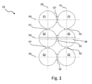
- the container 01 shown in whole or in part consists of a number A of articles 03 joined directly to one another by means of bonds 02.
- the articles 03 of the container 01 are arranged in a row 04 or in a line 05, or they are arranged in two or more parallel rows 04 and / or in two or more parallel lines 05 to two or more articles 03 regularly arranged at right angles or nested offset to each other.
- the articles 03 of the container 01 are therefore arranged in R rows 04 and Z rows 05, wherein the number of articles 03 per row 04 corresponds, for example, to the number Z of rows 05 in the container 01.
- a container 01 with mutually perpendicular rows 04 and lines 05 is in Fig. 1 shown.
- a container 01 with nested arranged articles 03 is in Fig. 2 shown.
- the rows 04 and lines 05 run obliquely or diagonally to each other, wherein the obliquely to the rows 04 extending lines in a plan view as in Fig. 2 a) may be V-shaped angled, or as in Fig. 2 b) can run straight shown.
- three of the connections of the centers of three articles 03 within an orthogonal arrangement form an isosceles and right triangle, in particular if the articles are substantially cylindrical.
- three of the connections of the centers of three articles 03 within a nested arrangement form an equilateral triangle, especially if the articles are substantially cylindrical.
- the bonds 02 are formed by one, two or more adhesive dots 20 of an adhesive applied to the shell surfaces of the articles 03 that collide in the bundle arrangement.
- An adhesion 02 between two articles 03 can accordingly as in Fig. 3 a) represented one, or as in Fig. 3 b) represented two or as in Fig. 3c) represented three or more, for example, along a distributed on a bottom 07 of the article 03 enclosing plane vertical axis arranged adhesive dots 20 include. It is sufficient if the articles 03 are brought together for the production of the finished container 01 and thereby approximated to each other so that the at least one applied at least on the outer surface of an article glue point another article at least touched.
- not all articles 03 within the package 01 with all its neighboring articles 03 must be directly connected.
- an article 03 inside the container 01 can be directly connected only to one, two or three articles 03 of all its neighboring articles 03.
- the finished container 01 may be provided with a carrying handle 06.
- the carrying handle 06 is applied directly to the surfaces of an article or preferably two articles.
- the invention provides an examination of the bonds 02 on the finished container 01 before.
- a method provided therefor for testing the bonds 02 between the articles 03 of a package 01 from articles 03 in at least one row 04 and / or at least one line 05 to at least two articles 03 directly connected to each other by bonds 02 is characterized by the fact that according to Completion of the container 01 the bonds 02 between at least two articles of the container are checked simultaneously and / or in quick succession.
- the bonds 02 between the articles 03 along the periphery of the container 01 are simultaneously and / or checked in quick succession.
- the method provides that the bonds 02 between all articles 03 of the container 01 are checked simultaneously and / or in quick succession.
- the method also provides to monitor and evaluate the reactions of the article 03 of the container 01 on the force and / or moment action.
- the evaluation provides that if it is determined during the monitoring that all articles 03 of the container 01 behave the same, for example, within the elasticity of the bonds 02 and the force and / or momentary action of proportional limits, on properly produced bonds 02 between the articles 03 of the container 01 is concluded.
- the evaluation further provides that if it is determined during the monitoring that at least two articles 03 of the container 01 behave differently, for example by exceeding the elasticity of the bonds 02 and the force and / or momentary action proportional limits to a deficient produced bond 02 is closed.
- the sum of the individual forces and / or moments acting on the articles 03 of the pack 01 subjected to the test of its bonds 02 is equal to zero. Accordingly, a moment and force compensation of the sum of the single forces acting on the individual articles 03 the container 01 individual forces and / or individual moments is advantageous.
- the method can provide that the forces occurring during the handling of the container 01 are determined experimentally and / or arithmetically prior to the testing of the bonds 02 between the articles 03 of the container 01 and as individual forces effecting a corresponding force and / or moment effect during the test and / or individual moments are given to the amount and preferably also in the direction according to the experimental and / or computational determination. This ensures that the force and / or moment action occurring during the test is within the limits to be borne by the bonds 02, for example during normal handling of the container 01.
- the direct monitoring by means of one or more contact switches and / or at least one video camera and at least one image recognition algorithm exporting image acquisition means can also be performed directly.
- at least one data processing device connected to a video camera and / or at least one microprocessor connected to at least one video camera can be provided, which executes the image recognition algorithm.
- the image recognition algorithm With the image recognition algorithm, the individual articles 03 of the container 01 in the captured video image are identifiable. As a result, their reactions to the force and / or moment action can be monitored in real time.
- the monitoring of the reactions of the article 03 of the container 01 on the force and / or moment action can alternatively or additionally be indirect, for example by the individual forces and / or moments are generated by each at least one electric or electromagnetic drive and / or actuator per article 03 , If, for example, electromagnetic actuators are used whose traction and / or compressive force and / or torque curve is proportional to their current consumption, then the current consumption of the actuators can be monitored in order to infer the force curve and thus the reaction of the respective article 03. A sudden drop in the current consumption of one or more actuators would indicate a failure of at least one bond 02 infer.
- the individual forces acting on the container 01 at least within one of the typically the lower sides 07 of the article 03 corresponding floor or floor surfaces of Article 03 of a container 01 enclosing plane parallel plane indicated by arrows Fx and arrows Fy individual force components, which the Article 03 of the container seen from an origin 10, for example, starting from a geometric center 09 of the container 01, apart or pull apart, so that the bonds 02 between the articles 03 experience at least one tensile component.
- the acting on in the container 01 adjacent Article 03 individual forces as in Fig. 4 indicated by arrows Fz at least in pairs in the amount and / or direction, so that, for example, in a row 04 or in a row 05 adjacent articles 03, a first article 03 a single force or a resultant single force component in a first direction and the first Article 03 of adjacent second article 03 learns a single force or a resultant single force component in a direction opposite to the first direction.
- These are preferably individual forces or individual force components resulting therefrom, which drive the adjacent articles 03 out of the container 01 in opposite directions normal to a plane running parallel to the bottom surfaces or contact surfaces of the articles 03 of a container 01 running parallel to the undersides 07 of the article 03 to attempt.
- the individual moments acting on the container 01 adjacent to the article 03 may differ in their magnitude and / or direction, so that, for example, in a row 04 or in a row 05 adjacent articles 03, a first article 03 a single moment in a first direction and a second article 03 adjacent to the first article 03 experiences a single moment in a direction opposite to the first direction.
- an equalization of moments is thus created in the amount of the same individual moments, since the sum of the torques acting on the articles 03 is equal to zero.
- at least two individual moments acting in opposite directions must additionally differ in magnitude in order to generate an instantaneous compensation.
- An article 03 located in the origin 10 formed, for example, by the geometric center 09 of a container 01, seen from which origin 10, for example, the container 01 acting on the individual articles 03 of the container 01 subjected to testing of the bonds 02 between its articles 03 apart or pull apart, as in Fig. 4 shown advantageous to be exposed to an indicated by an arrow M single moment.
- This single moment may be due to the vectorial sum of the acting on the remaining article 03 of the container 01, in Fig. 4 indicated by the arrows F and Fx and Fy individual forces and / or individual moments are compensated.
- Article 03 at least one shear stress component.
- Individual forces the pack 01 apart or pull apart are advantageously exposed to a single force, which is the origin 03 located in the normal Article 10 to a typical of the bottom or footprint of Article 03 of the container 01 forming bottoms 07 of the Article 03 enclosing plane from the Tried to drive out container 01.
- Fig. 4 indicated by the arrows Fz.
- Article 03 individual force can by the vectorial sum of acting on the remaining article 03 of the container 01 and in Fig. 4 indicated by arrows F individual forces are compensated so that at least the bonds 02 of the article 03 located in the origin 03 with its in the container 01 adjacent and by bonding 02 directly related to him articles 03 experience at least one shear stress component.
- the testing of the bonds 02 between the articles 03 of a package 01 as in Fig. 7 shown after the completion of the container 01 and prior to its stacking to a stack of similar containers 01 done at a stacking station 122.
- the test is carried out with the properly prepared bonds 02 for stacking to a stack of similar containers 01 provided at a stacking gripping the container 01.
- the container 01 is gripped here by taking all the articles 03 of the container 01 in the top 08 be, for example, by means of each article 03 individually grasping gripper tulips, suction cups or the like.
- the generation of the force required from individual forces and / or momentary action from individual moments required for the test takes place by pressing and / or pulling and / or rotating the articles 03 of the container 01 gripped in the area of their upper sides 08 and thereby exposing them to individual forces and / or individual moments.
- this can be done via a designated as palletizing stacking to a stack of similar containers 01 at a stacking already existing gripper head of the palletizer by the individual packing tulips of the gripper head are individually controlled and thus apply a test force on each article 03 of a container 01 can.
- the method may also provide that a container 01, in which at least one bond 02 between its articles 03 has been identified as deficient, is excluded from further handling, for example by using it as in Fig. 6 indicated by means of a container 01 with properly and poorly produced bonds 02 indicating evaluation 140 controllable switch 141, sorted out.
- a previously described method can be implemented, for example, by means of a method described in US Pat Fig. 6 or in Fig. 7 illustrated device 100 for testing the bonds 02 between the articles 03 of a container 01 in at least one row 04 and / or at least one line 05 to at least two articles 03 directly to each other by bonds 02 connected articles 03 are performed.
- the device 100 is characterized by test means 101, which at least two articles 03 of the container 01 at the same time and / or shortly after a force from Fig. 4 indicated by arrows F individual forces and / or a moment effect from in Fig. 4 Suspend indicated by arrows M single moments.
- the test means 101 set at least the article 03 along the periphery of the container 01 at the same time and / or shortly after one another from a force effect Fig. 4 indicated by arrows F individual forces and / or a moment effect from in Fig. 4 indicated by arrows M individual moments.
- test means 101 all the articles 03 of the container 01 at the same time and / or shortly after a force from Fig. 4 indicated by arrows F individual forces and / or a moment effect from in Fig. 4 indicated by arrows M individual moments.
- all bonds 02 between the articles 03 experience at least one tensile load and / or one shear stress, for example in the form of a tensile load component and / or a shear stress component and / or they are subjected to a moment load.
- the testing means 101 monitor directly or indirectly the reactions of the articles 03 of the container 01 on the force and / or moment action and evaluate these reactions to determine whether all bonds 02 between the articles 03 of the container 01 are made properly, or if one or several bonds 02 between the articles 03 of the container 01 are deficient.
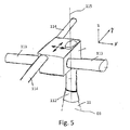
- each gripping tulip 112 of a gripping device 111 can be arranged movably driven along a first axis 113 and / or along an axis 114 perpendicular thereto.
- each gripping tulip 112 of a gripping device 111 may be movably driven along an axis 115 resting normally on a plane enclosing the axis 113 and the axis 114.
- each gripping tulip 112 of a gripping device 111 may be movably driven about an axis 115 resting normally on a plane enclosing the axis 113 and the axis 114 ( Fig. 5 ).
- the gripping device 111 with its gripping tulips 112 arranged independently of one another in each case in at least one direction of movement of the packings 02 between the articles 03 of a pack 01, is designed as a stack of similar packings designed to stack up adhesively bonded couplings 02 01 to a stack provided at a stacking position gripper head 118, which is designed with a number of gripping tulips 112, which corresponds at least to the number A of Article 03 of the container 01.
- the container 01 can be grasped here by taking all articles 03 of the container 01 in the area of their tops 08 by means of each article 03 of individually gripping gripping tulips 112.
- the checking means 101 also preferably comprise monitoring means 130, which generate at least one of the number A of articles 03 in the container 01 to be tested corresponding number of output signals, each of which formed by a movement and / or position change reaction of an article 03 of the container 01 on the force effect and / or moment action is proportional to individual forces and / or individual moments acting on the corresponding article 03.
- the monitoring means 130 may include sensors or devices that detect directly or indirectly by contact with the articles 03 or non-contact their reaction to the force and / or moment action.
- the monitoring means 130 may comprise one or more contact switches and / or at least one video camera together with at least one image recognition algorithm of performing image acquisition means.
- at least one data processing device connected to a video camera and / or at least one microprocessor connected to at least one video camera can be provided, which executes the image recognition algorithm.
- the image recognition algorithm With the image recognition algorithm, the individual articles of the container in the captured video image are identifiable. As a result, their reactions to the individual forces and / or individual moments can be monitored in real time.
- the monitoring means 130 may comprise devices which provide for an indirect detection of the reactions of the articles 03 of the container 01 to be tested on the acting individual forces and / or individual moments.
- Such indirect monitoring can take place, for example, by means of devices for detecting the power consumption of the individual forces and / or individual moments on one article 03 of the actuators 01 to be tested actuators and / or actuators of the force acting means 110. This corresponds to a monitoring of the forces and / or moment characteristic of the individual forces acting on the individual articles 03 of the container 01 to be tested 01 and / or individual moments.
- a sudden drop in power consumption of an actuator and / or actuator before completion of the test means that for a further increasing individual force and / or a further increasing single moment equivalent further deflection of an article compared to the remaining articles 03 of the container 01 no or suddenly reduced individual force and / or no or a sudden reduced individual moment is required, which suggests a failure of at least one bond 02 or at least one adhesive point 20 at least one of a plurality of adhesive dots 20 bond 02 of the respective article 03 with one of its adjacent article 03.
- a minimum current consumption may be predetermined in order to be able to infer from the outset on a defective bond 02 when the minimum current consumption is not reached.
- the monitoring means 130 in the respective at least one acting on an article 03 of the container to be tested 01 single force and / or on an article 03 of the container to be tested 01st acting single moment generating actuators and / or actuators of the force acting means 110 built incremental encoders include.
- the device 100 may further comprise separating means 144, which exclude a container 01, in which at least one bond 02 between its articles 03 has been identified as deficient, from further handling. This can be done by the separating means 144, for example, sort out a corresponding container 01, or provided by means of a label and by exclude identification by means of the identification as defective from the treatments taking place in the course of further handling.
- the separating means 144 may, as in Fig. 6 represented by a switchable by means of the evaluation means 140 switch 141 may be formed, which for example, directly to a collection point 145 in the form of a collection container or a leading to a collection point 145 in the form of a collection container Abtransportband 146 supplies with not properly prepared bonds 02 executed.
- test means could tear apart all articles 03 of the container 01 with a force greater than the test force at a recognized as defective bonding 02 of two articles 03 of a container 01 to return the article 03 a repeated gluing. In between can be provided, for example, by means of a cleaning device to separate old adhesive from the articles 03.
- the separating means 144 may alternatively as in Fig. 7 represented by a also referred to as palletizing stacking to a stack of similar containers 01 at a stacking 122 anyway necessary gripper head 118 of a palletizer 119 be realized, which container 01 with identified as properly executed bonds 02 feeds to a stacking station 122 resulting stack, and container 01 identified as poorly executed Verklebitch 02 to a provided away from the stacking space 122 collection point for bad products and supplies, for example, by the palletizer 119 containers 01 identified as poorly executed Verklebitch 02 directly to a collection point 145 in the form of, for example, a collection container or via a a collection point 145 in the form of, for example, a collecting container leading removal conveyor 146 indirectly feeds.
- the individual gripping tulips 112 also referred to as packing tulips, may be individually controllable in the directions of movement provided for testing the bonds 02 between the articles 03 of the package 01 and thus be able to apply a test force to each individual article 03 of a package 01 applied.
- the separating means 144 may be included by the force acting means 110.
- the invention can be realized by each of a test force on the bonds 02 between the articles 03 of a directly from each other by bonding 02 connected articles 03 existing container 01 exerting force and / or moment effect of at least two, particularly preferred However, applied to all individual articles 03 of the container 01 acting individual forces and / or individual moments.
- a variant consists in applying a predetermined individual force directly by way of a positioning drive in the form of, for example, a linear or rotary drive, for example a servomotor, which drives the gripping tulips 112, each holding an article 03. If a certain travel, which can be determined by a sensor seated in the actuator exceeded, so the bond 02 is torn and the container 01, or - if several containers 01 are taken simultaneously by the gripper head 118 and tested by applying test forces - the packaged layer is not deposited as a top stack layer on a pile stacked up to date on a pallet 122, for example, on a pallet, but instead on a collection point 145 serving as a collection point for bad articles and / or bad containers or a removal belt 146 leading there.
- a positioning drive in the form of, for example, a linear or rotary drive, for example a servomotor, which drives the gripping tulips 112, each holding an article 03. If a certain travel, which can be determined by a sensor
- the invention is not limited to a stacking 122 at a stacking gripper head 118, but may also take place in a separate module, which is upstream of a palletizer 119, for example, and on which the test forces, for example via turntable via the bottom sides 07 of the article 03 to one testing container 01 in so-called basehandling, or while gripping with Clamps, especially immediately after curing of the adhesive but still on the same Aushärteumble applied.
- the device 100 may, as in Fig. 6 and in Fig. 7 illustrated manufacturing means 150 for producing a container 01 from each other directly by bonding 02 together interconnected articles 03 include, or be arranged in the wake of such manufacturing means 150.
- the manufacturing means 150 include, for example, providing means 160 for a number R of rows 04 in the finished container 01 corresponding number of article strands 30 each one of the number of articles 03 in each row 04 or in the single row 04 in the finished container corresponding number of articles 03, as in Fig. 6 and in Fig. 7 shown.
- the provisioning means 160 may comprise an inflow of a number of article streams 31 each of directly consecutive articles 03 corresponding to the number R of the rows 04 in the finished package 01.
- the provisioning means 160 may also include per article stream 30 separating means 161, which separating means 161 an article strand 30 with a number of articles 03 per row 04 in the finished container 01 from the respective article flow 30 corresponding number of articles 03 separated from the respective article stream 31.
- the separating means 161 can, for example, operate on the principle that the article strand 30 is separated from the article stream 31 by an acceleration of the article 03 of an article strand 30 to be separated from an article stream 31 to a higher speed than that of the article stream 31.
- the manufacturing means 160 also comprise attachment means 162 for individual, selected or all articles 03 of the article strands 30 at least on their in the packaging arrangement of the finished container 01 with at least one lateral surface of another article 03 colliding lateral surfaces or at lots of their in the container assembly of the finished container 01 with at least one lateral surface of another article 03 colliding lateral surfaces with adhesive dots 20 to provide.
- the attachment means 162 can be realized by one or more nozzles 163, by means of which those serving for the production of bonds 02 serving Adhesive dots 20 can be applied to the outer surfaces of at least selected items 03, applied or can be applied.
- the one or more nozzles 163 may be realized by one or more, in particular V-shaped double nozzles, with which a simultaneous order of two or more adhesive dots 20 on an article 03 or a maximum of a simultaneous application of one adhesive dot 20 to one of the number the nozzle outlet openings of the double nozzle corresponding number of articles 03 is possible.
- a nozzle 163 realized by a double nozzle can be laterally connected to an article strand 30 which is not yet joined to another article strand 30 or laterally to its transport path from the separation of the article strand 30, for example, from its original article stream 31 until its merging with one or more other article strands 30 a finished container 01 or a intermediate container to be arranged, where they arranged an article 03 of the article strand 30 with two, for example, along which normal to a parallel to the rows 04 and lines 05 in the finished container 01 extending plane extending vertical axis arranged adhesive dots 20, or two in one and the same article strand 30 successive article 03 can each be provided with a glue dot 20.
- a double nozzle is also replaceable by two simple nozzles 163.
- nozzles 163 significantly reduces the number of nozzle elements required and thereby contributes to simplifying and reducing the space requirement of manufacturing means 150 suitable for producing a container 01 described. This allows cost savings in the design, construction, assembly and operation of corresponding manufacturing means 150, the latter also because of the reduction in space required for the establishment of the manufacturing means 150 by shortening.
- the manufacturing means 150 may moreover comprise at least one joining means 170 in order to merge the articles 03 provided with and / or without adhesive dots 20 in accordance with their arrangement in the finished package 01 such that they are directly joined together by the at least one bond 02 in the finished package 01 Articles 03 a corresponding bond 02 is made.
- the merging means 170 then provides that the articles 03 are pressed or held together for a certain time until the adhesive on the bond 02 thus produced has hardened between the articles 03 at least according to the introductory definition.
- the manufacturing means 150 may include first and second and optionally further joining means 170, first by means of first merging 170 a first row 04 in the finished container 01 forming the first article strand 30 and a second row 04 in the finished container 01 forming the second article strand 30, the Article 03 are at least partially provided with adhesive dots 20, according to the arrangement of the articles 03 of the first and second series 04 in the finished container 01 first merge into a tundish, then press against the adhesive dots 20 against each other and then at least until the curing of the adhesive to keep.
- second joining means 170 may be provided to form an intermediate container and at least one further series 04 in the finished container 01 forming further article strand 30, the article 03 - ie the article 03 of the intermediate package and / or the at least one further article strand 30. at least partially provided with adhesive dots 20, according to the arrangement of the article 03 of the intermediate container and the at least one further row 04 in the finished container 01 first to another intermediate container or the finished container 01st merge, then press against the adhesive dots 20 against each other and then to hold at least until the curing of the adhesive. If a further row 04 of articles 03 is still fed to an intermediate container, the production means 150 can also comprise third, fourth and so forth joining means 170, in order to add corresponding further rows 04 to the ever growing intermediate containers.
- the merging means 170 may be designed to be movable in whole or in part along a transport direction F in order to transport an intermediate container and / or a finished container 01 during the curing of the adhesive in the transport direction F.
- the joining means 170 may comprise, for example, at least one pressing unit 171 which presses the article 03 previously provided with adhesive dots 20 of the article strands 30 to be joined to a finished container 01 or to an intermediate container or of an intermediate container to be joined to a finished container 01 and of at least one further article strand 30 and at least until the curing of the adhesive holds against each other.
- a pressing unit 171 may, for example, comprise circumferential clamping units 172, which are individually and independently controllable and thus can also be seen during pressing and holding at different positions in the transport direction T seen.
- the manufacturing means 150 can also have an application unit for applying a carrying handle 06 to the finished container 01.
- a possible application unit for applying a carrying handle 06 may, for example, be arranged so as to be movable centrally above and, if appropriate, in the transport direction T above the joining means 170.
- the handle 06 is glued in particular directly on the lateral surface of two located in the container 01 Article 03.
- the manufacturing means 150 may also comprise alignment means which align at least the articles 03 provided with adhesive dots 20 according to their orientation required for the production of direct bonds of the articles 03 formed by bonds 02 in the finished package 01.
- the finished container 01 from each other by bonds 02 directly connected articles 03 are as in Fig. 6 and Fig. 7 shown preferably transported by means of, for example, designed as a belt conveyor 121 transport device 120 from the manufacturing means 150 to the testing means 101 of the device 100.
Landscapes
- Engineering & Computer Science (AREA)
- Mechanical Engineering (AREA)
- Packages (AREA)
- Investigating Strength Of Materials By Application Of Mechanical Stress (AREA)
Priority Applications (1)
| Application Number | Priority Date | Filing Date | Title |
|---|---|---|---|
| EP13195347.3A EP2878544B2 (fr) | 2013-12-02 | 2013-12-02 | Procédé et dispositif de contrôle des collages entre des articles d'une gerbe |
Applications Claiming Priority (1)
| Application Number | Priority Date | Filing Date | Title |
|---|---|---|---|
| EP13195347.3A EP2878544B2 (fr) | 2013-12-02 | 2013-12-02 | Procédé et dispositif de contrôle des collages entre des articles d'une gerbe |
Publications (3)
| Publication Number | Publication Date |
|---|---|
| EP2878544A1 true EP2878544A1 (fr) | 2015-06-03 |
| EP2878544B1 EP2878544B1 (fr) | 2016-02-24 |
| EP2878544B2 EP2878544B2 (fr) | 2023-01-11 |
Family
ID=49712977
Family Applications (1)
| Application Number | Title | Priority Date | Filing Date |
|---|---|---|---|
| EP13195347.3A Active EP2878544B2 (fr) | 2013-12-02 | 2013-12-02 | Procédé et dispositif de contrôle des collages entre des articles d'une gerbe |
Country Status (1)
| Country | Link |
|---|---|
| EP (1) | EP2878544B2 (fr) |
Cited By (1)
| Publication number | Priority date | Publication date | Assignee | Title |
|---|---|---|---|---|
| DE102019119101A1 (de) * | 2019-07-15 | 2021-01-21 | Krones Ag | Verfahren und Vorrichtung zum Herstellen von Gebinden mit mehreren unterschiedlichen Getränkebehältern |
Citations (9)
| Publication number | Priority date | Publication date | Assignee | Title |
|---|---|---|---|---|
| DE2331193A1 (de) | 1973-06-19 | 1975-01-16 | Coors Co Adolph | Grifflose, tragbare einheit aus einer anzahl von behaeltern |
| DE20310721U1 (de) | 2003-04-16 | 2003-09-18 | Pohl, Heinrich Robert, 50769 Köln | Behälter für Lebensmittel, insbesondere für Getränke und Anordnung von Behältern |
| DE102009044271A1 (de) | 2009-10-16 | 2011-04-28 | Krones Ag | Gebinde aus mehreren Behältern und Verfahren zur Herstellung eines solchen Gebindes |
| EP2183162B1 (fr) | 2007-08-23 | 2011-05-11 | KHS GmbH | Tête de robot d'emballage |
| US20120213956A1 (en) * | 2011-02-23 | 2012-08-23 | Adherent Laboratories, Inc. | Fugitive adhesive and method |
| DE102011106759B3 (de) | 2011-07-05 | 2012-09-13 | Khs Gmbh | Verfahren zur Herstellung von Gebinden |
| DE102011119966B3 (de) * | 2011-12-02 | 2012-11-22 | Khs Gmbh | Vorrichtung zur Bildung von Verpackungseinheiten |
| DE102011107265A1 (de) * | 2011-07-06 | 2013-01-10 | Khs Gmbh | Verfahren zur Herstellung von Gebinden |
| DE102011119964B3 (de) * | 2011-12-02 | 2013-01-17 | Khs Gmbh | Vorrichtung und Verfahren zur Bildung von Verpackungseinheiten |
Family Cites Families (4)
| Publication number | Priority date | Publication date | Assignee | Title |
|---|---|---|---|---|
| DE3816856A1 (de) | 1988-05-18 | 1989-11-30 | Focke & Co | Verfahren und vorrichtung zum pruefen von karton-packungen |
| AUPR003000A0 (en) | 2000-09-11 | 2000-10-05 | Tna Australia Pty Limited | A bag testing machine |
| US7048817B1 (en) | 2003-09-12 | 2006-05-23 | Hammond Ronald J | Method of making a composite carton |
| DE202010009972U1 (de) | 2010-07-02 | 2010-10-14 | Fifl Gmbh | Kolliprüfeinrichtung KPE |
-
2013
- 2013-12-02 EP EP13195347.3A patent/EP2878544B2/fr active Active
Patent Citations (9)
| Publication number | Priority date | Publication date | Assignee | Title |
|---|---|---|---|---|
| DE2331193A1 (de) | 1973-06-19 | 1975-01-16 | Coors Co Adolph | Grifflose, tragbare einheit aus einer anzahl von behaeltern |
| DE20310721U1 (de) | 2003-04-16 | 2003-09-18 | Pohl, Heinrich Robert, 50769 Köln | Behälter für Lebensmittel, insbesondere für Getränke und Anordnung von Behältern |
| EP2183162B1 (fr) | 2007-08-23 | 2011-05-11 | KHS GmbH | Tête de robot d'emballage |
| DE102009044271A1 (de) | 2009-10-16 | 2011-04-28 | Krones Ag | Gebinde aus mehreren Behältern und Verfahren zur Herstellung eines solchen Gebindes |
| US20120213956A1 (en) * | 2011-02-23 | 2012-08-23 | Adherent Laboratories, Inc. | Fugitive adhesive and method |
| DE102011106759B3 (de) | 2011-07-05 | 2012-09-13 | Khs Gmbh | Verfahren zur Herstellung von Gebinden |
| DE102011107265A1 (de) * | 2011-07-06 | 2013-01-10 | Khs Gmbh | Verfahren zur Herstellung von Gebinden |
| DE102011119966B3 (de) * | 2011-12-02 | 2012-11-22 | Khs Gmbh | Vorrichtung zur Bildung von Verpackungseinheiten |
| DE102011119964B3 (de) * | 2011-12-02 | 2013-01-17 | Khs Gmbh | Vorrichtung und Verfahren zur Bildung von Verpackungseinheiten |
Cited By (1)
| Publication number | Priority date | Publication date | Assignee | Title |
|---|---|---|---|---|
| DE102019119101A1 (de) * | 2019-07-15 | 2021-01-21 | Krones Ag | Verfahren und Vorrichtung zum Herstellen von Gebinden mit mehreren unterschiedlichen Getränkebehältern |
Also Published As
| Publication number | Publication date |
|---|---|
| EP2878544B2 (fr) | 2023-01-11 |
| EP2878544B1 (fr) | 2016-02-24 |
Similar Documents
| Publication | Publication Date | Title |
|---|---|---|
| AT522556B1 (de) | Vorrichtung und Verfahren zum Depalettieren von stapelbaren Stückgutgebinden | |
| DE102013204095A1 (de) | Verfahren und Vorrichtung zum Positionieren, Ausrichten und/oder Gruppieren von Artikeln, Stückgütern oder Gebinden | |
| WO2017182217A1 (fr) | Procédé et dispositif permettant la manutention de marchandises de détail déplacées sur au moins deux rangées parallèles | |
| EP2729377A1 (fr) | Emballage multiple et son procédé de réalisation | |
| DE102017205001A1 (de) | Vorrichtung und Verfahren zum Umgang mit bewegten Stückgütern sowie Förder-, Verarbeitungs- und/oder Verpackungsanlage für Stückgüter | |
| DE102013113325A1 (de) | Verfahren und Vorrichtung zur Prüfung von Verklebungen zwischen Artikeln eines Gebindes | |
| EP2803588B1 (fr) | Procédé et dispositif de fabrication de gerbe de cerclage et procédé de mesure destiné à détecter une tension de bande d'une telle gerbe de cerclage | |
| WO2013004339A1 (fr) | Emballage multiple et procédé de réalisation d'un tel emballage multiple | |
| DE102018212254A1 (de) | Handhabungs- und/oder Verpackungsvorrichtung und Verfahren zum Verpacken von Artikeln | |
| DE102019105834B4 (de) | Greifvorrichtung, Vereinzelungsvorrichtung sowie Verfahren zum Greifen von Körpern und Verwendung einer Greifvorrichtung | |
| DE102016212141A1 (de) | Einrichtung zur Begrenzung von Kollisionsschäden, Verfahren zu deren Herstellung sowie mit einer solchen ausgestatteten Vorrichtung zum Umgang mit Artikeln | |
| DE102013113321A1 (de) | Verfahren und Vorrichtung zur Prüfung von Verklebungen zwischen Artikeln eines Gebindes | |
| EP2878544B1 (fr) | Procédé et dispositif de contrôle des collages entre des articles d'une gerbe | |
| DE102019128197B4 (de) | Depalettieranordnung mit einer Vorrichtung zum Depalettieren von stapelbaren Stückgutgebinden und Verfahren zum Depalettieren von stapelbaren Stückgutgebinden | |
| DE102014104644A1 (de) | Verfahren zur Herstellung eines Gebindes aus untereinander durch ein Haftmittel verbundenen Artikeln | |
| EP2792625B2 (fr) | Procédé et dispositif de transport et de manipulation de lots comprenant au moins deux articles | |
| EP2878941B1 (fr) | Procédé et dispositif de contrôle des collages entre des articles d'un conteneur | |
| WO2015193136A1 (fr) | Procédé et dispositif permettant de relier des zones d'extrémité de bandes de cerclage constituées de matière plastique | |
| EP2930117B1 (fr) | Dispositif et procédé de fabrication de gerbes d'articles collées les uns aux autres à l'aide d'un adhésif | |
| EP3738896B1 (fr) | Dispositif d'emballage pour groupes d'articles et procédé d'application d'un flan de carton sur un groupe d'articles | |
| DE102021131120A1 (de) | Greifvorrichtung und Verfahren zur Handhabung von Stückgütern | |
| EP3445684A1 (fr) | Dispositif et procédé de manutention de marchandises de détail déplacées les unes derrière les autres sur au moins une rangée | |
| DE102016123770A1 (de) | System und Verfahren zum Umgang mit im Massenstrom bewegten Artikeln wie Getränkebehältnissen oder dergleichen | |
| WO2018095581A1 (fr) | Procédé et système pour le transport et la manipulation de récipients à boissons rassemblés en unités d'emballage ainsi que pour l'initialisation d'au moins un procédé déterminé dans le cas d'une dégradation d'une unité résultant d'une manipulation | |
| EP4245670B1 (fr) | Procédé de fabrication d'emballages et système d'emballage pour la mise en oeuvre du procédé |
Legal Events
| Date | Code | Title | Description |
|---|---|---|---|
| PUAI | Public reference made under article 153(3) epc to a published international application that has entered the european phase |
Free format text: ORIGINAL CODE: 0009012 |
|
| 17P | Request for examination filed |
Effective date: 20150306 |
|
| AK | Designated contracting states |
Kind code of ref document: A1 Designated state(s): AL AT BE BG CH CY CZ DE DK EE ES FI FR GB GR HR HU IE IS IT LI LT LU LV MC MK MT NL NO PL PT RO RS SE SI SK SM TR |
|
| AX | Request for extension of the european patent |
Extension state: BA ME |
|
| GRAP | Despatch of communication of intention to grant a patent |
Free format text: ORIGINAL CODE: EPIDOSNIGR1 |
|
| RIC1 | Information provided on ipc code assigned before grant |
Ipc: B65B 17/02 20060101AFI20150619BHEP Ipc: B65D 21/02 20060101ALI20150619BHEP Ipc: B65B 57/00 20060101ALI20150619BHEP |
|
| INTG | Intention to grant announced |
Effective date: 20150708 |
|
| GRAS | Grant fee paid |
Free format text: ORIGINAL CODE: EPIDOSNIGR3 |
|
| GRAR | Information related to intention to grant a patent recorded |
Free format text: ORIGINAL CODE: EPIDOSNIGR71 |
|
| INTG | Intention to grant announced |
Effective date: 20151104 |
|
| GRAA | (expected) grant |
Free format text: ORIGINAL CODE: 0009210 |
|
| AK | Designated contracting states |
Kind code of ref document: B1 Designated state(s): AL AT BE BG CH CY CZ DE DK EE ES FI FR GB GR HR HU IE IS IT LI LT LU LV MC MK MT NL NO PL PT RO RS SE SI SK SM TR |
|
| REG | Reference to a national code |
Ref country code: GB Ref legal event code: FG4D Free format text: NOT ENGLISH |
|
| REG | Reference to a national code |
Ref country code: CH Ref legal event code: EP |
|
| REG | Reference to a national code |
Ref country code: AT Ref legal event code: REF Ref document number: 776542 Country of ref document: AT Kind code of ref document: T Effective date: 20160315 |
|
| REG | Reference to a national code |
Ref country code: IE Ref legal event code: FG4D Free format text: LANGUAGE OF EP DOCUMENT: GERMAN |
|
| REG | Reference to a national code |
Ref country code: DE Ref legal event code: R096 Ref document number: 502013001992 Country of ref document: DE |
|
| REG | Reference to a national code |
Ref country code: LT Ref legal event code: MG4D |
|
| REG | Reference to a national code |
Ref country code: NL Ref legal event code: MP Effective date: 20160224 |
|
| PG25 | Lapsed in a contracting state [announced via postgrant information from national office to epo] |
Ref country code: ES Free format text: LAPSE BECAUSE OF FAILURE TO SUBMIT A TRANSLATION OF THE DESCRIPTION OR TO PAY THE FEE WITHIN THE PRESCRIBED TIME-LIMIT Effective date: 20160224 Ref country code: GR Free format text: LAPSE BECAUSE OF FAILURE TO SUBMIT A TRANSLATION OF THE DESCRIPTION OR TO PAY THE FEE WITHIN THE PRESCRIBED TIME-LIMIT Effective date: 20160525 Ref country code: FI Free format text: LAPSE BECAUSE OF FAILURE TO SUBMIT A TRANSLATION OF THE DESCRIPTION OR TO PAY THE FEE WITHIN THE PRESCRIBED TIME-LIMIT Effective date: 20160224 Ref country code: NO Free format text: LAPSE BECAUSE OF FAILURE TO SUBMIT A TRANSLATION OF THE DESCRIPTION OR TO PAY THE FEE WITHIN THE PRESCRIBED TIME-LIMIT Effective date: 20160524 Ref country code: HR Free format text: LAPSE BECAUSE OF FAILURE TO SUBMIT A TRANSLATION OF THE DESCRIPTION OR TO PAY THE FEE WITHIN THE PRESCRIBED TIME-LIMIT Effective date: 20160224 |
|
| PG25 | Lapsed in a contracting state [announced via postgrant information from national office to epo] |
Ref country code: LV Free format text: LAPSE BECAUSE OF FAILURE TO SUBMIT A TRANSLATION OF THE DESCRIPTION OR TO PAY THE FEE WITHIN THE PRESCRIBED TIME-LIMIT Effective date: 20160224 Ref country code: NL Free format text: LAPSE BECAUSE OF FAILURE TO SUBMIT A TRANSLATION OF THE DESCRIPTION OR TO PAY THE FEE WITHIN THE PRESCRIBED TIME-LIMIT Effective date: 20160224 Ref country code: RS Free format text: LAPSE BECAUSE OF FAILURE TO SUBMIT A TRANSLATION OF THE DESCRIPTION OR TO PAY THE FEE WITHIN THE PRESCRIBED TIME-LIMIT Effective date: 20160224 Ref country code: LT Free format text: LAPSE BECAUSE OF FAILURE TO SUBMIT A TRANSLATION OF THE DESCRIPTION OR TO PAY THE FEE WITHIN THE PRESCRIBED TIME-LIMIT Effective date: 20160224 Ref country code: PT Free format text: LAPSE BECAUSE OF FAILURE TO SUBMIT A TRANSLATION OF THE DESCRIPTION OR TO PAY THE FEE WITHIN THE PRESCRIBED TIME-LIMIT Effective date: 20160624 Ref country code: PL Free format text: LAPSE BECAUSE OF FAILURE TO SUBMIT A TRANSLATION OF THE DESCRIPTION OR TO PAY THE FEE WITHIN THE PRESCRIBED TIME-LIMIT Effective date: 20160224 Ref country code: SE Free format text: LAPSE BECAUSE OF FAILURE TO SUBMIT A TRANSLATION OF THE DESCRIPTION OR TO PAY THE FEE WITHIN THE PRESCRIBED TIME-LIMIT Effective date: 20160224 |
|
| PG25 | Lapsed in a contracting state [announced via postgrant information from national office to epo] |
Ref country code: EE Free format text: LAPSE BECAUSE OF FAILURE TO SUBMIT A TRANSLATION OF THE DESCRIPTION OR TO PAY THE FEE WITHIN THE PRESCRIBED TIME-LIMIT Effective date: 20160224 Ref country code: DK Free format text: LAPSE BECAUSE OF FAILURE TO SUBMIT A TRANSLATION OF THE DESCRIPTION OR TO PAY THE FEE WITHIN THE PRESCRIBED TIME-LIMIT Effective date: 20160224 |
|
| REG | Reference to a national code |
Ref country code: FR Ref legal event code: PLFP Year of fee payment: 4 |
|
| REG | Reference to a national code |
Ref country code: DE Ref legal event code: R026 Ref document number: 502013001992 Country of ref document: DE |
|
| PG25 | Lapsed in a contracting state [announced via postgrant information from national office to epo] |
Ref country code: RO Free format text: LAPSE BECAUSE OF FAILURE TO SUBMIT A TRANSLATION OF THE DESCRIPTION OR TO PAY THE FEE WITHIN THE PRESCRIBED TIME-LIMIT Effective date: 20160224 Ref country code: SK Free format text: LAPSE BECAUSE OF FAILURE TO SUBMIT A TRANSLATION OF THE DESCRIPTION OR TO PAY THE FEE WITHIN THE PRESCRIBED TIME-LIMIT Effective date: 20160224 Ref country code: SM Free format text: LAPSE BECAUSE OF FAILURE TO SUBMIT A TRANSLATION OF THE DESCRIPTION OR TO PAY THE FEE WITHIN THE PRESCRIBED TIME-LIMIT Effective date: 20160224 Ref country code: CZ Free format text: LAPSE BECAUSE OF FAILURE TO SUBMIT A TRANSLATION OF THE DESCRIPTION OR TO PAY THE FEE WITHIN THE PRESCRIBED TIME-LIMIT Effective date: 20160224 |
|
| PLBI | Opposition filed |
Free format text: ORIGINAL CODE: 0009260 |
|
| 26 | Opposition filed |
Opponent name: KHS GMBH Effective date: 20161124 |
|
| PLAX | Notice of opposition and request to file observation + time limit sent |
Free format text: ORIGINAL CODE: EPIDOSNOBS2 |
|
| PG25 | Lapsed in a contracting state [announced via postgrant information from national office to epo] |
Ref country code: BG Free format text: LAPSE BECAUSE OF FAILURE TO SUBMIT A TRANSLATION OF THE DESCRIPTION OR TO PAY THE FEE WITHIN THE PRESCRIBED TIME-LIMIT Effective date: 20160524 Ref country code: SI Free format text: LAPSE BECAUSE OF FAILURE TO SUBMIT A TRANSLATION OF THE DESCRIPTION OR TO PAY THE FEE WITHIN THE PRESCRIBED TIME-LIMIT Effective date: 20160224 |
|
| PLBB | Reply of patent proprietor to notice(s) of opposition received |
Free format text: ORIGINAL CODE: EPIDOSNOBS3 |
|
| PG25 | Lapsed in a contracting state [announced via postgrant information from national office to epo] |
Ref country code: BE Free format text: LAPSE BECAUSE OF NON-PAYMENT OF DUE FEES Effective date: 20161231 |
|
| REG | Reference to a national code |
Ref country code: CH Ref legal event code: PL |
|
| PG25 | Lapsed in a contracting state [announced via postgrant information from national office to epo] |
Ref country code: MC Free format text: LAPSE BECAUSE OF FAILURE TO SUBMIT A TRANSLATION OF THE DESCRIPTION OR TO PAY THE FEE WITHIN THE PRESCRIBED TIME-LIMIT Effective date: 20160224 |
|
| REG | Reference to a national code |
Ref country code: IE Ref legal event code: MM4A |
|
| PG25 | Lapsed in a contracting state [announced via postgrant information from national office to epo] |
Ref country code: CH Free format text: LAPSE BECAUSE OF NON-PAYMENT OF DUE FEES Effective date: 20161231 Ref country code: LU Free format text: LAPSE BECAUSE OF NON-PAYMENT OF DUE FEES Effective date: 20161202 Ref country code: LI Free format text: LAPSE BECAUSE OF NON-PAYMENT OF DUE FEES Effective date: 20161231 |
|
| REG | Reference to a national code |
Ref country code: FR Ref legal event code: PLFP Year of fee payment: 5 |
|
| PG25 | Lapsed in a contracting state [announced via postgrant information from national office to epo] |
Ref country code: IE Free format text: LAPSE BECAUSE OF NON-PAYMENT OF DUE FEES Effective date: 20161202 |
|
| REG | Reference to a national code |
Ref country code: BE Ref legal event code: MM Effective date: 20161231 |
|
| PG25 | Lapsed in a contracting state [announced via postgrant information from national office to epo] |
Ref country code: HU Free format text: LAPSE BECAUSE OF FAILURE TO SUBMIT A TRANSLATION OF THE DESCRIPTION OR TO PAY THE FEE WITHIN THE PRESCRIBED TIME-LIMIT; INVALID AB INITIO Effective date: 20131202 |
|
| PG25 | Lapsed in a contracting state [announced via postgrant information from national office to epo] |
Ref country code: CY Free format text: LAPSE BECAUSE OF FAILURE TO SUBMIT A TRANSLATION OF THE DESCRIPTION OR TO PAY THE FEE WITHIN THE PRESCRIBED TIME-LIMIT Effective date: 20160224 Ref country code: IS Free format text: LAPSE BECAUSE OF FAILURE TO SUBMIT A TRANSLATION OF THE DESCRIPTION OR TO PAY THE FEE WITHIN THE PRESCRIBED TIME-LIMIT Effective date: 20160224 Ref country code: MK Free format text: LAPSE BECAUSE OF FAILURE TO SUBMIT A TRANSLATION OF THE DESCRIPTION OR TO PAY THE FEE WITHIN THE PRESCRIBED TIME-LIMIT Effective date: 20160224 |
|
| GBPC | Gb: european patent ceased through non-payment of renewal fee |
Effective date: 20171202 |
|
| PG25 | Lapsed in a contracting state [announced via postgrant information from national office to epo] |
Ref country code: MT Free format text: LAPSE BECAUSE OF FAILURE TO SUBMIT A TRANSLATION OF THE DESCRIPTION OR TO PAY THE FEE WITHIN THE PRESCRIBED TIME-LIMIT Effective date: 20160224 |
|
| PG25 | Lapsed in a contracting state [announced via postgrant information from national office to epo] |
Ref country code: AL Free format text: LAPSE BECAUSE OF FAILURE TO SUBMIT A TRANSLATION OF THE DESCRIPTION OR TO PAY THE FEE WITHIN THE PRESCRIBED TIME-LIMIT Effective date: 20160224 Ref country code: TR Free format text: LAPSE BECAUSE OF FAILURE TO SUBMIT A TRANSLATION OF THE DESCRIPTION OR TO PAY THE FEE WITHIN THE PRESCRIBED TIME-LIMIT Effective date: 20160224 |
|
| PG25 | Lapsed in a contracting state [announced via postgrant information from national office to epo] |
Ref country code: GB Free format text: LAPSE BECAUSE OF NON-PAYMENT OF DUE FEES Effective date: 20171202 |
|
| APAH | Appeal reference modified |
Free format text: ORIGINAL CODE: EPIDOSCREFNO |
|
| APBM | Appeal reference recorded |
Free format text: ORIGINAL CODE: EPIDOSNREFNO |
|
| APBP | Date of receipt of notice of appeal recorded |
Free format text: ORIGINAL CODE: EPIDOSNNOA2O |
|
| APBQ | Date of receipt of statement of grounds of appeal recorded |
Free format text: ORIGINAL CODE: EPIDOSNNOA3O |
|
| REG | Reference to a national code |
Ref country code: AT Ref legal event code: MM01 Ref document number: 776542 Country of ref document: AT Kind code of ref document: T Effective date: 20181202 |
|
| PG25 | Lapsed in a contracting state [announced via postgrant information from national office to epo] |
Ref country code: AT Free format text: LAPSE BECAUSE OF NON-PAYMENT OF DUE FEES Effective date: 20181202 |
|
| APBU | Appeal procedure closed |
Free format text: ORIGINAL CODE: EPIDOSNNOA9O |
|
| PUAH | Patent maintained in amended form |
Free format text: ORIGINAL CODE: 0009272 |
|
| STAA | Information on the status of an ep patent application or granted ep patent |
Free format text: STATUS: PATENT MAINTAINED AS AMENDED |
|
| 27A | Patent maintained in amended form |
Effective date: 20230111 |
|
| AK | Designated contracting states |
Kind code of ref document: B2 Designated state(s): AL AT BE BG CH CY CZ DE DK EE ES FI FR GB GR HR HU IE IS IT LI LT LU LV MC MK MT NL NO PL PT RO RS SE SI SK SM TR |
|
| REG | Reference to a national code |
Ref country code: DE Ref legal event code: R102 Ref document number: 502013001992 Country of ref document: DE |
|
| P01 | Opt-out of the competence of the unified patent court (upc) registered |
Effective date: 20230523 |
|
| REG | Reference to a national code |
Ref country code: DE Ref legal event code: R082 Ref document number: 502013001992 Country of ref document: DE Representative=s name: BENNINGER, JOHANNES, DIPL.-ING., DE |
|
| PGFP | Annual fee paid to national office [announced via postgrant information from national office to epo] |
Ref country code: DE Payment date: 20251104 Year of fee payment: 13 |
|
| PGFP | Annual fee paid to national office [announced via postgrant information from national office to epo] |
Ref country code: IT Payment date: 20251121 Year of fee payment: 13 |
|
| PGFP | Annual fee paid to national office [announced via postgrant information from national office to epo] |
Ref country code: FR Payment date: 20251110 Year of fee payment: 13 |