EP2879472A1 - Boîtier pour un appareil de commande - Google Patents
Boîtier pour un appareil de commande Download PDFInfo
- Publication number
- EP2879472A1 EP2879472A1 EP14003597.3A EP14003597A EP2879472A1 EP 2879472 A1 EP2879472 A1 EP 2879472A1 EP 14003597 A EP14003597 A EP 14003597A EP 2879472 A1 EP2879472 A1 EP 2879472A1
- Authority
- EP
- European Patent Office
- Prior art keywords
- cover
- housing base
- housing
- front wall
- wall
- Prior art date
- Legal status (The legal status is an assumption and is not a legal conclusion. Google has not performed a legal analysis and makes no representation as to the accuracy of the status listed.)
- Granted
Links
Images


Classifications
-
- H—ELECTRICITY
- H05—ELECTRIC TECHNIQUES NOT OTHERWISE PROVIDED FOR
- H05K—PRINTED CIRCUITS; CASINGS OR CONSTRUCTIONAL DETAILS OF ELECTRIC APPARATUS; MANUFACTURE OF ASSEMBLAGES OF ELECTRICAL COMPONENTS
- H05K5/00—Casings, cabinets or drawers for electric apparatus
- H05K5/10—Casings, cabinets or drawers for electric apparatus comprising several parts forming a closed casing
- H05K5/15—Casings, cabinets or drawers for electric apparatus comprising several parts forming a closed casing assembled by resilient members
-
- B—PERFORMING OPERATIONS; TRANSPORTING
- B60—VEHICLES IN GENERAL
- B60T—VEHICLE BRAKE CONTROL SYSTEMS OR PARTS THEREOF; BRAKE CONTROL SYSTEMS OR PARTS THEREOF, IN GENERAL; ARRANGEMENT OF BRAKING ELEMENTS ON VEHICLES IN GENERAL; PORTABLE DEVICES FOR PREVENTING UNWANTED MOVEMENT OF VEHICLES; VEHICLE MODIFICATIONS TO FACILITATE COOLING OF BRAKES
- B60T8/00—Arrangements for adjusting wheel-braking force to meet varying vehicular or ground-surface conditions, e.g. limiting or varying distribution of braking force
- B60T8/32—Arrangements for adjusting wheel-braking force to meet varying vehicular or ground-surface conditions, e.g. limiting or varying distribution of braking force responsive to a speed condition, e.g. acceleration or deceleration
- B60T8/34—Arrangements for adjusting wheel-braking force to meet varying vehicular or ground-surface conditions, e.g. limiting or varying distribution of braking force responsive to a speed condition, e.g. acceleration or deceleration having a fluid pressure regulator responsive to a speed condition
- B60T8/36—Arrangements for adjusting wheel-braking force to meet varying vehicular or ground-surface conditions, e.g. limiting or varying distribution of braking force responsive to a speed condition, e.g. acceleration or deceleration having a fluid pressure regulator responsive to a speed condition including a pilot valve responding to an electromagnetic force
- B60T8/3615—Electromagnetic valves specially adapted for anti-lock brake and traction control systems
- B60T8/3675—Electromagnetic valves specially adapted for anti-lock brake and traction control systems integrated in modulator units
Definitions
- the invention relates to a housing for a control unit, comprising a housing base, are mounted on the cable via external assemblies connectable control components, a hood-like cover with an upper top wall, a rear wall, two side walls and a front wall, at the lower edge of which cable penetrations forming recesses are formed , And with on the housing base on the one hand and the cover on the other hand arranged latching means which engage in the sliding of the cover on the housing base.
- Electrical or electronic control devices usually contain sensitive electrical, mechanical or pressure medium control components that must be protected from environmental influences.
- control units are often located at locations where they are exposed to pollution, moisture and mechanical stress.
- the housings for such control devices must therefore be such that they ensure adequate protection against such environmental influences. Because of the generally limited installation space, it is also important that for maintenance and repair purposes, the control components are made as easy as possible, so that a cover of the controller is easy and removable with a small release stroke.
- a hood-like cover is pushed for mounting on a housing block consisting of a housing block and a housing cover housing base, wherein the sliding of the cover on the housing base on the one hand and the cover on the other arranged locking means interlock.
- a folded edge strip snaps elastically behind a housing cover edge.
- the folded edge strip In order to disassemble the cover, the folded edge strip must be moved elastically from its securing position and then the cover to be moved in the dismounting direction.
- the cover is therefore relatively light and flexible, so that it at least does not provide sufficient protection against mechanical stress, in particular, for example, no tread resistance.
- the invention has the object to provide a housing for a control device referred to in the preamble of claim 1, which provides a sufficient protection against sprayed and sprayed water, dust and dirt and mechanical loads when installed, the cover should be removable with the lowest possible release stroke.
- the invention relates to a control unit comprising a housing base on which control components connectable via cables to external units are mounted, a hood-like cover having an upper cover wall, a rear wall, two side walls and a front wall, at the lower edge of which cable ducts forming recesses are formed, and with on the housing base on the one hand and the cover on the other hand arranged latching means which engage in the sliding of the cover on the housing base.
- top, bottom, rear and front refer to a normal position of the control unit, in which the cover is pushed in a horizontal plane from back to front on the housing base becomes.
- the cover For mounting the cover on the housing base, the cover is thus pushed over the housing base, that the tab extension of the cover engages in the channel of the housing base, wherein the cover is pressed in its rear region due to the described configuration of the channel down to the housing base.
- the Laschenfortsatz the cover may be formed beaded thickened according to a favorable embodiment of the invention to its end edge and thus forms with the groove bottom joint pan-like rounded gutter a kind of pivot joint, which allows lifting only the front portion of the cover upwards.
- a related embodiment of the invention provides that against a displacement of the cover back locking locking means have at least one arranged on a side wall, downwardly projecting projection, which in the assembled state, ie at lowered front end of the cover, in an associated recess the housing base engages.
- the relevant latching means have at least one locking tab arranged on the front wall of the cover, which can be latched in the assembled state of the cover with a detent formed on the housing base, or vice versa, that is Latching tab may be disposed on the housing base and the latching lug on the cover.
- a second embodiment of the present invention relates to the same housing for a control unit, comprising a housing base on which control components connectable via cables to external units, a hood-like cover having an upper top wall, a rear wall, two side walls and a front wall at the lower edge thereof Cable recesses forming recesses are formed, and arranged on the housing base on the one hand and the cover on the other hand latching means which engage in the sliding of the cover on the housing base.
- the securing against a displacement to the rear latching means comprise according to a further embodiment of the invention at least one arranged on a side wall of the cover latching tab which is latched in the assembled state of the cover with a formed on the housing base locking lug, or vice versa, that is, the at least one Latching tab and the at least one locking lug can also be arranged reversed.
- the front wall of the cover each extends down to the level of standing on the housing base front wall, wherein at the upper edge of the front wall of the housing base approximately part-circular recesses are formed, which with part-circular recesses at the lower edge of the front wall Add cover to substantially circular cable glands.
- the cable feedthrough openings have a slightly smaller diameter than the cable passing therethrough, so that the cables are clamped in the assembly of the cover in the sense of a strain relief something.
- the latching lugs or latching tabs described above, formed on the housing base are each formed or arranged according to a further embodiment of the invention on the above-described front wall of the housing base, as will be explained with reference to embodiments.
- extending grooves for collecting and discharging water running off the cover are formed on the upper side of the housing base along the side walls of the mounted cover.
- the rear lower edge of the cover is beveled so that it forms a drip edge for running water splashing.
- a guide nose is arranged, which engages when closing the cover in an associated, formed on the front wall of the housing base recess.
- FIG. 1 illustrated control unit 2 has a housing base 4, are mounted on the not shown here in detail control components and sockets, and a hood-like cover 6, which can be placed on the housing base 4 and removed from this.
- the housing base 4 has fastening eyes 8, which can receive fastening screws for fastening the control unit to a machine to be controlled, for example in a motor vehicle.
- a vertical front wall 10 is arranged on the upper edge of which four part-circular recesses 12 are used for guiding and holding cables, not shown, which are connectable with arranged on the housing base sockets.
- the cover 6 consists essentially of a top wall 14, one in Fig.1 invisible, because the viewer facing away from the rear wall 16, two side walls 18, of which in the perspective view again only one can be seen, and a front side of the cover 6 only partially final front wall 20.
- This front wall 20 is aligned in the mounted and closed position of Cover 6 substantially with the front wall 10 of the housing base 4.
- part-circular recesses 22 are formed, which complement with the recesses 12 on the front wall 10 of the housing base 4 to substantially circular cable passage openings.
- FIGS. 2 and 3 let recognize when accessing the cover 6 from the in Fig. 1 shown position on the lower edge of the rear wall 16th arranged Laschenfortsatz 28 in a formed on the housing base 4 channel 30, which has a forward substantially wedge-shaped tapered cross-section.
- the trailing edge of the cover 6 is pressed down when pushed in the direction of the arrow 26 down to the housing base 4.
- latchable and releasable locking means are provided in the front region of the cover 6 on the one hand and the housing base 4 on the other hand, which secure the cover against lifting and sliding backwards, as will be described below.
- Fig. 3 shows, at least on a side wall 18 of the cover 6, a downwardly projecting projection 34 is formed, which engages in the assembled, ie downwardly pivoted state of the cover 6 in an associated recess 36 on the housing base 4. In this way, a displacement of the cover 6 is prevented to the rear.
- the Fig. 3 also shows one opposite Fig. 2 slightly modified embodiment of a tab extension 38, which is bead-like thickened toward its end edge and forms a kind of pivot joint with the approximately joint cup-like rounded bottom of the associated channel 40.
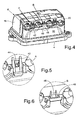
- FIG. 4 To secure the cover 6 against being lifted out of the closed position, as shown in FIG Fig. 4 is shown, on the front wall 20 of the cover 6 elastic locking tabs 42 which are latched with formed on the front wall 10 of the housing base 4, each associated locking lugs 44.
- Fig. 5 shows this detail in section A in an enlarged view. The locking tabs 42 can be easily removed manually, so without tools to remove the cover.
- Fig. 6 shows this detail in a section B in an enlarged view.
- the rear lower edge of the cover 6 formed by the respective tab extension 28, 38 forms a chamfer and thus serves as a drip edge for running spray water.
- the housing base 4 and the cover 6 are preferably designed so that the cover 6 remains when moving within the base surface of the housing base 4.
- FIGS. 7 and 8 show a controller 50 with a housing base 52 and a cover 54.
- the cover 54 is similar in construction as the cover 6 in the FIGS. 1 and 4 that is, it has a top wall 56, a rear wall 58 and two side walls 60 and an oblique front wall 62 in the present case, which rests against a front wall 64 of the housing base 52 in the closed state of the cover.
- each circular cable bushing openings 66th again on the lower edge of the front wall 62 of the cover 54 on the one hand and on the upper edge of the front wall 64 of the housing base 52 on the other hand formed recesses each circular cable bushing openings 66th
- two locking cams 68, 69 are formed in each case at a distance, when the cover 54 is pushed into associated side walls 70 of the housing base 52, which are open towards the rear, inclined obliquely downwards and forwards and narrowing Locking slots 72, 73 engage. Because of the oblique configuration of the latching slots 72, 73, the cover 56 is pushed down on the housing base 52 when advancing in the direction of the arrow 74.
- the rear lower edge 78 of the cover 54 is in turn bevelled and forms a drip edge for spray water.
- grooves 80 are formed for collecting and discharging water spray.
Landscapes
- Physics & Mathematics (AREA)
- Engineering & Computer Science (AREA)
- Electromagnetism (AREA)
- Fluid Mechanics (AREA)
- Transportation (AREA)
- Mechanical Engineering (AREA)
- Microelectronics & Electronic Packaging (AREA)
- Casings For Electric Apparatus (AREA)
Applications Claiming Priority (1)
| Application Number | Priority Date | Filing Date | Title |
|---|---|---|---|
| DE102013020255.8A DE102013020255A1 (de) | 2013-11-29 | 2013-11-29 | Gehäuse für ein Steuergerät |
Publications (2)
| Publication Number | Publication Date |
|---|---|
| EP2879472A1 true EP2879472A1 (fr) | 2015-06-03 |
| EP2879472B1 EP2879472B1 (fr) | 2018-01-17 |
Family
ID=51795478
Family Applications (1)
| Application Number | Title | Priority Date | Filing Date |
|---|---|---|---|
| EP14003597.3A Active EP2879472B1 (fr) | 2013-11-29 | 2014-10-22 | Boîtier pour un appareil de commande |
Country Status (2)
| Country | Link |
|---|---|
| EP (1) | EP2879472B1 (fr) |
| DE (1) | DE102013020255A1 (fr) |
Cited By (1)
| Publication number | Priority date | Publication date | Assignee | Title |
|---|---|---|---|---|
| CN114727897A (zh) * | 2019-11-15 | 2022-07-08 | 利纳克有限公司 | 控制单元 |
Families Citing this family (1)
| Publication number | Priority date | Publication date | Assignee | Title |
|---|---|---|---|---|
| JP6137737B2 (ja) * | 2015-09-11 | 2017-05-31 | 株式会社安川電機 | 電気機器筐体及び電力変換装置 |
Citations (6)
| Publication number | Priority date | Publication date | Assignee | Title |
|---|---|---|---|---|
| US4126224A (en) * | 1977-11-03 | 1978-11-21 | Laauwe Robert H | Moisture-proof and child-resistant pill box |
| CH659164A5 (en) * | 1983-05-16 | 1986-12-31 | Gfeller Ag | Housing to receive an electronic device |
| US5497036A (en) * | 1994-10-21 | 1996-03-05 | Harley-Davidson | Motorcycle terminal box assembly |
| DE19545011A1 (de) * | 1995-10-05 | 1997-04-10 | Teves Gmbh Alfred | Ventilblockaggregat für eine Steuer- und/oder Regelvorrichtung, insbesondere für hyraulische und/oder pneumatische Kraftfahrzeugbremsanlagen |
| US5762224A (en) * | 1995-03-10 | 1998-06-09 | Ericsson Raynet | Environmental enclosure and method of sealing same |
| DE19528252B4 (de) | 1995-08-01 | 2009-06-25 | Knorr-Bremse Systeme für Nutzfahrzeuge GmbH | Aggregat für eine Fahrzeugbremsanlage |
-
2013
- 2013-11-29 DE DE102013020255.8A patent/DE102013020255A1/de not_active Withdrawn
-
2014
- 2014-10-22 EP EP14003597.3A patent/EP2879472B1/fr active Active
Patent Citations (6)
| Publication number | Priority date | Publication date | Assignee | Title |
|---|---|---|---|---|
| US4126224A (en) * | 1977-11-03 | 1978-11-21 | Laauwe Robert H | Moisture-proof and child-resistant pill box |
| CH659164A5 (en) * | 1983-05-16 | 1986-12-31 | Gfeller Ag | Housing to receive an electronic device |
| US5497036A (en) * | 1994-10-21 | 1996-03-05 | Harley-Davidson | Motorcycle terminal box assembly |
| US5762224A (en) * | 1995-03-10 | 1998-06-09 | Ericsson Raynet | Environmental enclosure and method of sealing same |
| DE19528252B4 (de) | 1995-08-01 | 2009-06-25 | Knorr-Bremse Systeme für Nutzfahrzeuge GmbH | Aggregat für eine Fahrzeugbremsanlage |
| DE19545011A1 (de) * | 1995-10-05 | 1997-04-10 | Teves Gmbh Alfred | Ventilblockaggregat für eine Steuer- und/oder Regelvorrichtung, insbesondere für hyraulische und/oder pneumatische Kraftfahrzeugbremsanlagen |
Cited By (2)
| Publication number | Priority date | Publication date | Assignee | Title |
|---|---|---|---|---|
| CN114727897A (zh) * | 2019-11-15 | 2022-07-08 | 利纳克有限公司 | 控制单元 |
| CN114727897B (zh) * | 2019-11-15 | 2023-12-26 | 利纳克有限公司 | 控制单元 |
Also Published As
| Publication number | Publication date |
|---|---|
| EP2879472B1 (fr) | 2018-01-17 |
| DE102013020255A1 (de) | 2015-06-03 |
Similar Documents
| Publication | Publication Date | Title |
|---|---|---|
| DE102014101405B4 (de) | Bodenbaugruppe für das Rahmengestell eines Schaltschranks | |
| EP2084339B1 (fr) | Grille de recouvrement | |
| EP2339701B1 (fr) | Connecteur à fiche de plaquettes doté d'un dispositif de verrouillage | |
| DE102011056494A1 (de) | Set aus Paneelen mit Clip | |
| DE102015222561A1 (de) | Halterahmen zur Halterung von Steckverbindermodulen | |
| DE202017107144U1 (de) | Set aus Steckverbinder und Halteelement sowie Steckverbinder und Halteelement hierzu | |
| EP2879472B1 (fr) | Boîtier pour un appareil de commande | |
| EP2114200B1 (fr) | Pupitre de commande | |
| DE102010017424A1 (de) | Vorrichtung zum Verriegeln einer Abdeckung | |
| DE102016201425A1 (de) | Befestigungsvorrichtung | |
| DE102018221627A1 (de) | Kabeldurchführung für einen Durchbruch in einer Platte | |
| DE69510627T2 (de) | Geräteträgereinrichtung Einzubringen auf einen Kabelkanalkörper | |
| DE202016101089U1 (de) | Installationsbox | |
| DE69204265T2 (de) | Rastverbindungssystem für das losbare Verbinden von Teilen einer Einheit, insbesondere für elektrische Installationsdosen. | |
| EP2418746A2 (fr) | Boîtier d'appareillage pour appareils dýinstallation | |
| DE3206526A1 (de) | Befestigungseinrichtung fuer einen spiegel | |
| DE69738519T2 (de) | Befestigungsvorrichtung für Elektrohaushaltsgeräte, für Befestigung von einem elektrischen Bauelement | |
| DE102008013640B4 (de) | Eckverbinder zum Verbinden von Hohlprofil-Rahmenteilen zur Abstandshalterung von Isolierglasscheiben sowie Isolierglasfenster | |
| DE69804703T2 (de) | Kanalverbindung | |
| EP0606850A2 (fr) | Accumulateur avec panneau de recouvrement détachable couvrant les bornes | |
| EP3931924B1 (fr) | Assemblage avec une armoire électrique et au moins une barre multiprise | |
| EP0430271B1 (fr) | Grille de plafond suspendu | |
| DE29514740U1 (de) | Elektrischer Steckverbinder | |
| DE202026100174U1 (de) | Verdrahtungskanal | |
| DE102025106848A1 (de) | Dachfenster mit einer externen Abschirmvorrichtung und Verfahren zur Montage einer solchen Abschirmvorrichtung |
Legal Events
| Date | Code | Title | Description |
|---|---|---|---|
| PUAI | Public reference made under article 153(3) epc to a published international application that has entered the european phase |
Free format text: ORIGINAL CODE: 0009012 |
|
| 17P | Request for examination filed |
Effective date: 20141022 |
|
| AK | Designated contracting states |
Kind code of ref document: A1 Designated state(s): AL AT BE BG CH CY CZ DE DK EE ES FI FR GB GR HR HU IE IS IT LI LT LU LV MC MK MT NL NO PL PT RO RS SE SI SK SM TR |
|
| AX | Request for extension of the european patent |
Extension state: BA ME |
|
| R17P | Request for examination filed (corrected) |
Effective date: 20151203 |
|
| RBV | Designated contracting states (corrected) |
Designated state(s): AL AT BE BG CH CY CZ DE DK EE ES FI FR GB GR HR HU IE IS IT LI LT LU LV MC MK MT NL NO PL PT RO RS SE SI SK SM TR |
|
| GRAP | Despatch of communication of intention to grant a patent |
Free format text: ORIGINAL CODE: EPIDOSNIGR1 |
|
| INTG | Intention to grant announced |
Effective date: 20170925 |
|
| GRAS | Grant fee paid |
Free format text: ORIGINAL CODE: EPIDOSNIGR3 |
|
| GRAA | (expected) grant |
Free format text: ORIGINAL CODE: 0009210 |
|
| AK | Designated contracting states |
Kind code of ref document: B1 Designated state(s): AL AT BE BG CH CY CZ DE DK EE ES FI FR GB GR HR HU IE IS IT LI LT LU LV MC MK MT NL NO PL PT RO RS SE SI SK SM TR |
|
| REG | Reference to a national code |
Ref country code: GB Ref legal event code: FG4D Free format text: NOT ENGLISH |
|
| REG | Reference to a national code |
Ref country code: CH Ref legal event code: EP |
|
| REG | Reference to a national code |
Ref country code: IE Ref legal event code: FG4D Free format text: LANGUAGE OF EP DOCUMENT: GERMAN |
|
| REG | Reference to a national code |
Ref country code: AT Ref legal event code: REF Ref document number: 965238 Country of ref document: AT Kind code of ref document: T Effective date: 20180215 |
|
| REG | Reference to a national code |
Ref country code: DE Ref legal event code: R096 Ref document number: 502014006967 Country of ref document: DE |
|
| REG | Reference to a national code |
Ref country code: SE Ref legal event code: TRGR |
|
| REG | Reference to a national code |
Ref country code: NL Ref legal event code: MP Effective date: 20180117 |
|
| REG | Reference to a national code |
Ref country code: LT Ref legal event code: MG4D |
|
| PG25 | Lapsed in a contracting state [announced via postgrant information from national office to epo] |
Ref country code: NL Free format text: LAPSE BECAUSE OF FAILURE TO SUBMIT A TRANSLATION OF THE DESCRIPTION OR TO PAY THE FEE WITHIN THE PRESCRIBED TIME-LIMIT Effective date: 20180117 |
|
| PG25 | Lapsed in a contracting state [announced via postgrant information from national office to epo] |
Ref country code: LT Free format text: LAPSE BECAUSE OF FAILURE TO SUBMIT A TRANSLATION OF THE DESCRIPTION OR TO PAY THE FEE WITHIN THE PRESCRIBED TIME-LIMIT Effective date: 20180117 Ref country code: CY Free format text: LAPSE BECAUSE OF FAILURE TO SUBMIT A TRANSLATION OF THE DESCRIPTION OR TO PAY THE FEE WITHIN THE PRESCRIBED TIME-LIMIT Effective date: 20180117 Ref country code: FI Free format text: LAPSE BECAUSE OF FAILURE TO SUBMIT A TRANSLATION OF THE DESCRIPTION OR TO PAY THE FEE WITHIN THE PRESCRIBED TIME-LIMIT Effective date: 20180117 Ref country code: NO Free format text: LAPSE BECAUSE OF FAILURE TO SUBMIT A TRANSLATION OF THE DESCRIPTION OR TO PAY THE FEE WITHIN THE PRESCRIBED TIME-LIMIT Effective date: 20180417 Ref country code: ES Free format text: LAPSE BECAUSE OF FAILURE TO SUBMIT A TRANSLATION OF THE DESCRIPTION OR TO PAY THE FEE WITHIN THE PRESCRIBED TIME-LIMIT Effective date: 20180117 Ref country code: HR Free format text: LAPSE BECAUSE OF FAILURE TO SUBMIT A TRANSLATION OF THE DESCRIPTION OR TO PAY THE FEE WITHIN THE PRESCRIBED TIME-LIMIT Effective date: 20180117 |
|
| PG25 | Lapsed in a contracting state [announced via postgrant information from national office to epo] |
Ref country code: RS Free format text: LAPSE BECAUSE OF FAILURE TO SUBMIT A TRANSLATION OF THE DESCRIPTION OR TO PAY THE FEE WITHIN THE PRESCRIBED TIME-LIMIT Effective date: 20180117 Ref country code: LV Free format text: LAPSE BECAUSE OF FAILURE TO SUBMIT A TRANSLATION OF THE DESCRIPTION OR TO PAY THE FEE WITHIN THE PRESCRIBED TIME-LIMIT Effective date: 20180117 Ref country code: GR Free format text: LAPSE BECAUSE OF FAILURE TO SUBMIT A TRANSLATION OF THE DESCRIPTION OR TO PAY THE FEE WITHIN THE PRESCRIBED TIME-LIMIT Effective date: 20180418 Ref country code: PL Free format text: LAPSE BECAUSE OF FAILURE TO SUBMIT A TRANSLATION OF THE DESCRIPTION OR TO PAY THE FEE WITHIN THE PRESCRIBED TIME-LIMIT Effective date: 20180117 Ref country code: IS Free format text: LAPSE BECAUSE OF FAILURE TO SUBMIT A TRANSLATION OF THE DESCRIPTION OR TO PAY THE FEE WITHIN THE PRESCRIBED TIME-LIMIT Effective date: 20180517 Ref country code: BG Free format text: LAPSE BECAUSE OF FAILURE TO SUBMIT A TRANSLATION OF THE DESCRIPTION OR TO PAY THE FEE WITHIN THE PRESCRIBED TIME-LIMIT Effective date: 20180417 |
|
| PG25 | Lapsed in a contracting state [announced via postgrant information from national office to epo] |
Ref country code: MT Free format text: LAPSE BECAUSE OF FAILURE TO SUBMIT A TRANSLATION OF THE DESCRIPTION OR TO PAY THE FEE WITHIN THE PRESCRIBED TIME-LIMIT Effective date: 20180117 |
|
| REG | Reference to a national code |
Ref country code: DE Ref legal event code: R097 Ref document number: 502014006967 Country of ref document: DE |
|
| PG25 | Lapsed in a contracting state [announced via postgrant information from national office to epo] |
Ref country code: AL Free format text: LAPSE BECAUSE OF FAILURE TO SUBMIT A TRANSLATION OF THE DESCRIPTION OR TO PAY THE FEE WITHIN THE PRESCRIBED TIME-LIMIT Effective date: 20180117 Ref country code: IT Free format text: LAPSE BECAUSE OF FAILURE TO SUBMIT A TRANSLATION OF THE DESCRIPTION OR TO PAY THE FEE WITHIN THE PRESCRIBED TIME-LIMIT Effective date: 20180117 Ref country code: EE Free format text: LAPSE BECAUSE OF FAILURE TO SUBMIT A TRANSLATION OF THE DESCRIPTION OR TO PAY THE FEE WITHIN THE PRESCRIBED TIME-LIMIT Effective date: 20180117 Ref country code: RO Free format text: LAPSE BECAUSE OF FAILURE TO SUBMIT A TRANSLATION OF THE DESCRIPTION OR TO PAY THE FEE WITHIN THE PRESCRIBED TIME-LIMIT Effective date: 20180117 |
|
| PLBE | No opposition filed within time limit |
Free format text: ORIGINAL CODE: 0009261 |
|
| STAA | Information on the status of an ep patent application or granted ep patent |
Free format text: STATUS: NO OPPOSITION FILED WITHIN TIME LIMIT |
|
| PG25 | Lapsed in a contracting state [announced via postgrant information from national office to epo] |
Ref country code: SK Free format text: LAPSE BECAUSE OF FAILURE TO SUBMIT A TRANSLATION OF THE DESCRIPTION OR TO PAY THE FEE WITHIN THE PRESCRIBED TIME-LIMIT Effective date: 20180117 Ref country code: CZ Free format text: LAPSE BECAUSE OF FAILURE TO SUBMIT A TRANSLATION OF THE DESCRIPTION OR TO PAY THE FEE WITHIN THE PRESCRIBED TIME-LIMIT Effective date: 20180117 Ref country code: DK Free format text: LAPSE BECAUSE OF FAILURE TO SUBMIT A TRANSLATION OF THE DESCRIPTION OR TO PAY THE FEE WITHIN THE PRESCRIBED TIME-LIMIT Effective date: 20180117 Ref country code: SM Free format text: LAPSE BECAUSE OF FAILURE TO SUBMIT A TRANSLATION OF THE DESCRIPTION OR TO PAY THE FEE WITHIN THE PRESCRIBED TIME-LIMIT Effective date: 20180117 |
|
| 26N | No opposition filed |
Effective date: 20181018 |
|
| PG25 | Lapsed in a contracting state [announced via postgrant information from national office to epo] |
Ref country code: SI Free format text: LAPSE BECAUSE OF FAILURE TO SUBMIT A TRANSLATION OF THE DESCRIPTION OR TO PAY THE FEE WITHIN THE PRESCRIBED TIME-LIMIT Effective date: 20180117 |
|
| REG | Reference to a national code |
Ref country code: CH Ref legal event code: PL |
|
| GBPC | Gb: european patent ceased through non-payment of renewal fee |
Effective date: 20181022 |
|
| REG | Reference to a national code |
Ref country code: BE Ref legal event code: MM Effective date: 20181031 |
|
| PG25 | Lapsed in a contracting state [announced via postgrant information from national office to epo] |
Ref country code: MC Free format text: LAPSE BECAUSE OF FAILURE TO SUBMIT A TRANSLATION OF THE DESCRIPTION OR TO PAY THE FEE WITHIN THE PRESCRIBED TIME-LIMIT Effective date: 20180117 Ref country code: LU Free format text: LAPSE BECAUSE OF NON-PAYMENT OF DUE FEES Effective date: 20181022 |
|
| REG | Reference to a national code |
Ref country code: IE Ref legal event code: MM4A |
|
| PG25 | Lapsed in a contracting state [announced via postgrant information from national office to epo] |
Ref country code: FR Free format text: LAPSE BECAUSE OF NON-PAYMENT OF DUE FEES Effective date: 20181031 Ref country code: CH Free format text: LAPSE BECAUSE OF NON-PAYMENT OF DUE FEES Effective date: 20181031 Ref country code: LI Free format text: LAPSE BECAUSE OF NON-PAYMENT OF DUE FEES Effective date: 20181031 Ref country code: BE Free format text: LAPSE BECAUSE OF NON-PAYMENT OF DUE FEES Effective date: 20181031 |
|
| PG25 | Lapsed in a contracting state [announced via postgrant information from national office to epo] |
Ref country code: IE Free format text: LAPSE BECAUSE OF NON-PAYMENT OF DUE FEES Effective date: 20181022 Ref country code: GB Free format text: LAPSE BECAUSE OF NON-PAYMENT OF DUE FEES Effective date: 20181022 |
|
| PG25 | Lapsed in a contracting state [announced via postgrant information from national office to epo] |
Ref country code: PT Free format text: LAPSE BECAUSE OF FAILURE TO SUBMIT A TRANSLATION OF THE DESCRIPTION OR TO PAY THE FEE WITHIN THE PRESCRIBED TIME-LIMIT Effective date: 20180117 |
|
| PG25 | Lapsed in a contracting state [announced via postgrant information from national office to epo] |
Ref country code: MK Free format text: LAPSE BECAUSE OF NON-PAYMENT OF DUE FEES Effective date: 20180117 Ref country code: HU Free format text: LAPSE BECAUSE OF FAILURE TO SUBMIT A TRANSLATION OF THE DESCRIPTION OR TO PAY THE FEE WITHIN THE PRESCRIBED TIME-LIMIT; INVALID AB INITIO Effective date: 20141022 |
|
| REG | Reference to a national code |
Ref country code: AT Ref legal event code: MM01 Ref document number: 965238 Country of ref document: AT Kind code of ref document: T Effective date: 20191022 |
|
| PG25 | Lapsed in a contracting state [announced via postgrant information from national office to epo] |
Ref country code: AT Free format text: LAPSE BECAUSE OF NON-PAYMENT OF DUE FEES Effective date: 20191022 |
|
| REG | Reference to a national code |
Ref country code: DE Ref legal event code: R081 Ref document number: 502014006967 Country of ref document: DE Owner name: ZF CV SYSTEMS EUROPE BV, BE Free format text: FORMER OWNER: WABCO GMBH, 30453 HANNOVER, DE Ref country code: DE Ref legal event code: R081 Ref document number: 502014006967 Country of ref document: DE Owner name: ZF CV SYSTEMS HANNOVER GMBH, DE Free format text: FORMER OWNER: WABCO GMBH, 30453 HANNOVER, DE |
|
| REG | Reference to a national code |
Ref country code: DE Ref legal event code: R081 Ref document number: 502014006967 Country of ref document: DE Owner name: ZF CV SYSTEMS EUROPE BV, BE Free format text: FORMER OWNER: ZF CV SYSTEMS HANNOVER GMBH, 30453 HANNOVER, DE |
|
| P01 | Opt-out of the competence of the unified patent court (upc) registered |
Effective date: 20230528 |
|
| PGFP | Annual fee paid to national office [announced via postgrant information from national office to epo] |
Ref country code: TR Payment date: 20241002 Year of fee payment: 11 |
|
| PGFP | Annual fee paid to national office [announced via postgrant information from national office to epo] |
Ref country code: SE Payment date: 20250910 Year of fee payment: 12 |
|
| PGFP | Annual fee paid to national office [announced via postgrant information from national office to epo] |
Ref country code: DE Payment date: 20250902 Year of fee payment: 12 |