EP2882020A1 - Brennstoffzelle - Google Patents
Brennstoffzelle Download PDFInfo
- Publication number
- EP2882020A1 EP2882020A1 EP13826285.2A EP13826285A EP2882020A1 EP 2882020 A1 EP2882020 A1 EP 2882020A1 EP 13826285 A EP13826285 A EP 13826285A EP 2882020 A1 EP2882020 A1 EP 2882020A1
- Authority
- EP
- European Patent Office
- Prior art keywords
- air electrode
- fuel cell
- separator body
- middle layer
- separator
- Prior art date
- Legal status (The legal status is an assumption and is not a legal conclusion. Google has not performed a legal analysis and makes no representation as to the accuracy of the status listed.)
- Withdrawn
Links
Images



Classifications
-
- H—ELECTRICITY
- H01—ELECTRIC ELEMENTS
- H01M—PROCESSES OR MEANS, e.g. BATTERIES, FOR THE DIRECT CONVERSION OF CHEMICAL ENERGY INTO ELECTRICAL ENERGY
- H01M8/00—Fuel cells; Manufacture thereof
- H01M8/24—Grouping of fuel cells, e.g. stacking of fuel cells
- H01M8/241—Grouping of fuel cells, e.g. stacking of fuel cells with solid or matrix-supported electrolytes
- H01M8/2425—High-temperature cells with solid electrolytes
- H01M8/2435—High-temperature cells with solid electrolytes with monolithic core structure, e.g. honeycombs
-
- H—ELECTRICITY
- H01—ELECTRIC ELEMENTS
- H01M—PROCESSES OR MEANS, e.g. BATTERIES, FOR THE DIRECT CONVERSION OF CHEMICAL ENERGY INTO ELECTRICAL ENERGY
- H01M8/00—Fuel cells; Manufacture thereof
- H01M8/02—Details
- H01M8/0202—Collectors; Separators, e.g. bipolar separators; Interconnectors
- H01M8/0204—Non-porous and characterised by the material
- H01M8/0223—Composites
- H01M8/0228—Composites in the form of layered or coated products
-
- H—ELECTRICITY
- H01—ELECTRIC ELEMENTS
- H01M—PROCESSES OR MEANS, e.g. BATTERIES, FOR THE DIRECT CONVERSION OF CHEMICAL ENERGY INTO ELECTRICAL ENERGY
- H01M8/00—Fuel cells; Manufacture thereof
- H01M8/10—Fuel cells with solid electrolytes
- H01M8/12—Fuel cells with solid electrolytes operating at high temperature, e.g. with stabilised ZrO2 electrolyte
- H01M8/1213—Fuel cells with solid electrolytes operating at high temperature, e.g. with stabilised ZrO2 electrolyte characterised by the electrode/electrolyte combination or the supporting material
-
- H—ELECTRICITY
- H01—ELECTRIC ELEMENTS
- H01M—PROCESSES OR MEANS, e.g. BATTERIES, FOR THE DIRECT CONVERSION OF CHEMICAL ENERGY INTO ELECTRICAL ENERGY
- H01M8/00—Fuel cells; Manufacture thereof
- H01M8/24—Grouping of fuel cells, e.g. stacking of fuel cells
- H01M8/241—Grouping of fuel cells, e.g. stacking of fuel cells with solid or matrix-supported electrolytes
- H01M8/2425—High-temperature cells with solid electrolytes
- H01M8/2432—Grouping of unit cells of planar configuration
-
- H—ELECTRICITY
- H01—ELECTRIC ELEMENTS
- H01M—PROCESSES OR MEANS, e.g. BATTERIES, FOR THE DIRECT CONVERSION OF CHEMICAL ENERGY INTO ELECTRICAL ENERGY
- H01M8/00—Fuel cells; Manufacture thereof
- H01M8/10—Fuel cells with solid electrolytes
- H01M8/12—Fuel cells with solid electrolytes operating at high temperature, e.g. with stabilised ZrO2 electrolyte
- H01M2008/1293—Fuel cells with solid oxide electrolytes
-
- H—ELECTRICITY
- H01—ELECTRIC ELEMENTS
- H01M—PROCESSES OR MEANS, e.g. BATTERIES, FOR THE DIRECT CONVERSION OF CHEMICAL ENERGY INTO ELECTRICAL ENERGY
- H01M2300/00—Electrolytes
- H01M2300/0017—Non-aqueous electrolytes
- H01M2300/0065—Solid electrolytes
- H01M2300/0068—Solid electrolytes inorganic
- H01M2300/0071—Oxides
- H01M2300/0074—Ion conductive at high temperature
-
- H—ELECTRICITY
- H01—ELECTRIC ELEMENTS
- H01M—PROCESSES OR MEANS, e.g. BATTERIES, FOR THE DIRECT CONVERSION OF CHEMICAL ENERGY INTO ELECTRICAL ENERGY
- H01M2300/00—Electrolytes
- H01M2300/0088—Composites
- H01M2300/0094—Composites in the form of layered products, e.g. coatings
-
- H—ELECTRICITY
- H01—ELECTRIC ELEMENTS
- H01M—PROCESSES OR MEANS, e.g. BATTERIES, FOR THE DIRECT CONVERSION OF CHEMICAL ENERGY INTO ELECTRICAL ENERGY
- H01M4/00—Electrodes
- H01M4/86—Inert electrodes with catalytic activity, e.g. for fuel cells
- H01M4/90—Selection of catalytic material
- H01M4/9016—Oxides, hydroxides or oxygenated metallic salts
- H01M4/9025—Oxides specially used in fuel cell operating at high temperature, e.g. SOFC
- H01M4/9033—Complex oxides, optionally doped, of the type M1MeO3, M1 being an alkaline earth metal or a rare earth, Me being a metal, e.g. perovskites
-
- H—ELECTRICITY
- H01—ELECTRIC ELEMENTS
- H01M—PROCESSES OR MEANS, e.g. BATTERIES, FOR THE DIRECT CONVERSION OF CHEMICAL ENERGY INTO ELECTRICAL ENERGY
- H01M8/00—Fuel cells; Manufacture thereof
- H01M8/02—Details
- H01M8/0202—Collectors; Separators, e.g. bipolar separators; Interconnectors
- H01M8/0247—Collectors; Separators, e.g. bipolar separators; Interconnectors characterised by the form
- H01M8/0256—Vias, i.e. connectors passing through the separator material
-
- Y—GENERAL TAGGING OF NEW TECHNOLOGICAL DEVELOPMENTS; GENERAL TAGGING OF CROSS-SECTIONAL TECHNOLOGIES SPANNING OVER SEVERAL SECTIONS OF THE IPC; TECHNICAL SUBJECTS COVERED BY FORMER USPC CROSS-REFERENCE ART COLLECTIONS [XRACs] AND DIGESTS
- Y02—TECHNOLOGIES OR APPLICATIONS FOR MITIGATION OR ADAPTATION AGAINST CLIMATE CHANGE
- Y02E—REDUCTION OF GREENHOUSE GAS [GHG] EMISSIONS, RELATED TO ENERGY GENERATION, TRANSMISSION OR DISTRIBUTION
- Y02E60/00—Enabling technologies; Technologies with a potential or indirect contribution to GHG emissions mitigation
- Y02E60/30—Hydrogen technology
- Y02E60/50—Fuel cells
Definitions
- the present invention relates to a fuel cell.
- the present invention relates particularly to a solid oxide fuel cell.
- Fuel cells include solid oxide fuel cells (SOFC), molten carbonate fuel cells, phosphoric acid fuel cell and solid polymer fuel cells.
- SOFC solid oxide fuel cells
- molten carbonate fuel cells molten carbonate fuel cells
- phosphoric acid fuel cell molten carbonate fuel cells
- solid polymer fuel cells solid oxide fuel cells
- solid oxide fuel cells do not necessarily need to use a liquid constituent and are capable of reforming a hydrocarbon fuel in their interior when the hydrocarbon fuel is used.
- Patent Literature 1 describes one example of solid oxide fuel cells.
- Patent Literature 2 describes use of an air electrode containing a perovskite-type oxide represented by ABO 3 .
- the present invention has a major object to provide a fuel cell having improved reliability.
- the fuel cell according to the present invention has a power generating component and a separator.
- the power generating component has a solid oxide electrolyte layer, an air electrode and a fuel electrode.
- the air electrode is disposed on one principal surface of the solid oxide electrolyte layer.
- the air electrode contains a perovskite-type oxide.
- the fuel electrode is disposed on the other principal surface of the solid oxide electrolyte layer.
- the separator is disposed on the air electrode.
- the separator has flow paths facing the air electrode and demarcated and formed thereon.
- the separator has a separator body and interconnectors.
- the interconnectors are disposed in the separator body.
- the interconnectors are connected to the air electrode.
- the fuel cell according to the present invention further has a middle layer to suppress the diffusion of constitutional elements of the air electrode to the separator body.
- the middle layer is disposed between the separator body and the air electrode.
- the middle layer is formed of a ceramic.
- the separator body is formed of a ceramic.
- the middle layer preferably contains a (Ce 1-x D x )O 2 wherein D is at least one selected from the group consisting of Y, La, Pr, Nd, Sm, Eu, Gd, Tb, Dy, Ho, Er, Tm, Yb and Lu, and 0 ⁇ x ⁇ 0.5.
- x is 0.
- the power generating component further has another middle layer disposed between the solid oxide electrolyte layer and the air electrode.
- the another middle layer contains a (Ce 1-x D x )O 2 wherein D is at least one selected from the group consisting of Y, La, Pr, Nd, Sm, Eu, Gd, Tb, Dy, Ho, Er, Tm, Yb and Lu, and 0 ⁇ x ⁇ 0.5.
- the air electrode contains ABO 3 .
- A is at least one among rare earth elements and alkaline earth elements.
- B is at least one selected from the group consisting of Co, Fe and Ni.
- the air electrode contains at least one selected from the group consisting of (La,Sr)CoO 3 , (Sm,Sr)CoO 3 , (La,Sr)FeO 3 , (La, Sr) (Co,Fe)O 3 , (Ba,Sr) (Co,Fe)O 3 and La(Ni,Fe)O 3 .
- the separator body contains at least one of stabilized zirconias and partially stabilized zirconias stabilized with a stabilizing material.
- the separator body has a first part and a second part.
- the first part is disposed on the air electrode.
- the first part has flow paths demarcated and formed thereon.
- the second part is disposed in a region of the separator body where the air electrode is not provided.
- the second part is provided with flow paths through which a fuel gas to be supplied to the fuel electrode passes.
- the middle layer does not contact with the second part.
- the present invention can provide a fuel cell having improved reliability.
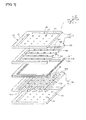
- Figure 1 is a schematic exploded perspective view of a fuel cell according to a first embodiment.
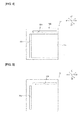
- Figure 2 is a schematic plan view of a first separator body in the first embodiment.
- Figure 3 is a schematic plan view of a first flow path forming member in the first embodiment.
- Figure 4 is a schematic plan view of an air electrode layer in the first embodiment.
- Figure 5 is a schematic plan view of a solid oxide electrolyte layer in the first embodiment.
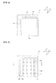
- Figure 6 is a schematic plan view of a fuel electrode layer in the first embodiment.
- Figure 7 is a schematic plan view of a second flow path forming member in the first embodiment.
- Figure 8 is a schematic plan view of a second separator body in the first embodiment.
- Figure 9 is a schematic cross-sectional view taken on line IX-IX in Figure 3 .
- Figure 10 is a schematic cross-sectional view taken on line X-X in Figure 7 .
- a solid oxide fuel cell 1 As shown in Figure 1 , Figure 9 and Figure 10 , a solid oxide fuel cell 1 according to the present embodiment has a first separator 10, a power generating component 30, and a second separator 50. In the solid oxide fuel cell 1, the first separator 10, the power generating component 30 and the second separator 50 are stacked in this order.
- the solid oxide fuel cell 1 according to the present embodiment has only one power generating component 30.
- the present invention is not limited to this constitution.
- the solid oxide fuel cell according to the present invention may have, for example, a plurality of power generating components. In this case, adjacent power generating components are separated by a separator.
- the electric connection between power generating components can be carried out by interconnectors.
- the interconnectors may be provided as separate bodies from separators, or separators may be made to have also a function as interconnectors by constituting the separators of an electroconductive material. That is, the interconnectors may be formed as unified bodies with the separators.
- the power generating component 30 is a section in which an oxidizing agent gas supplied from an oxidizing agent gas flow path (manifold for the oxidizing agent gas) 61 and a fuel gas supplied from a fuel gas flow path (manifold for the fuel gas) 62 are allowed to react to thereby generate a power.
- the oxidizing agent gas can be composed of, for example, an oxygen-containing gas or the like such as air or oxygen gas.
- the fuel gas can be a gas containing hydrogen gas or a hydrocarbon gas such as carbon monoxide gas, or the like.
- the power generating component 30 has a solid oxide electrolyte layer 31.
- the solid oxide electrolyte layer 31 preferably has a high ionic conductivity.
- the solid oxide electrolyte layer 31 can be formed of, for example, a stabilized zirconia or partially stabilized zirconia.
- the stabilized zirconia include an 8-mol% yttria-stabilized zirconia (8YSZ), a 10-mol% yttria-stabilized zirconia (10YSZ), a 10-mol% scandia 1-mol% ceria-stabilized zirconia (10Sc1CeSZ) and an 11-mol% scandia-stabilized zirconia (11ScSZ)
- the partially stabilized zirconia include a 3-mol% yttria-partially stabilized zirconia (3YSZ).
- the solid oxide electrolyte layer 31 can also be formed of, for example, a ceria-based oxide doped with Sm, Gd or the like, a perovskite-type oxide such as La 0.8 Sr 0.2 Ga 0.8 Mg 0.2 O( 3 - ⁇ ) having LaGaO 3 as a base and Sr and Mg respectively replacing part of La and Ga, or the like.
- a ceria-based oxide doped with Sm, Gd or the like a perovskite-type oxide such as La 0.8 Sr 0.2 Ga 0.8 Mg 0.2 O( 3 - ⁇ ) having LaGaO 3 as a base and Sr and Mg respectively replacing part of La and Ga, or the like.
- the solid oxide electrolyte layer 31 is interposed between an air electrode layer 32 and a fuel electrode layer 33. That is, the air electrode layer 32 is formed on one principal surface of the solid oxide electrolyte layer 31, and the fuel electrode layer 33 is formed on the other principal surface thereof.
- the air electrode layer 32 has an air electrode 32a and a peripheral part 32b.
- throughholes 32c, 32d constituting part of the flow paths 61, 62 are formed.
- the air electrode 32a is a cathode. In the air electrode 32a, oxygen takes electrons, and oxygen ions are formed.
- the air electrode 32a is preferably one which is porous and high in electron conductivity and hardly causes a solid-solid reaction with the solid oxide electrolyte layer 31 and the like at a high temperature.
- the air electrode 32a preferably contains a perovskite-type oxide represented by ABO 3 , and is more preferably constituted substantially of a perovskite-type oxide represented by ABO 3 .
- A is preferably, for example, at least one among rare earth elements and alkaline earth elements
- B is preferably, for example, at least one selected from the group consisting of Co, Fe and Ni.
- perovskite-type oxide represented by ABO 3 preferably include (La,Sr)CoO 3 (LSC), (Sm,Sr)CoO 3 (SSC), (La,Sr)FeO 3 (LSF), (La, Sr) (Co, Fe) O 3 (LSCF), (Ba,Sr)(Co,Fe)O 3 (BSCF) and La(Ni,Fe)O 3 (LNF), and mixtures thereof.
- the peripheral part 32b can be formed of, for example, the same material as first and second separator bodies 11, 51 described below.
- the fuel electrode layer 33 has a fuel electrode 33a and a peripheral part 33b.
- throughholes 33c, 33d constituting part of the flow paths 61, 62 are formed.
- the fuel electrode 33a is an anode. In the fuel electrode 33a, oxygen ions and a fuel gas react and release electrons.
- the fuel electrode 33a is preferably one which is porous and high in electron conductivity and hardly causes a solid-solid reaction with the solid oxide electrolyte layer 31 and the like at a high temperature.
- the fuel electrode 33a can be constituted of, for example, nickel oxide, a Ni-containing yttrium oxide-stabilized zirconia (yttria-stabilized zirconia (YSZ)), a Ni-containing calcium oxide-stabilized zirconia, a Ni-containing scandium oxide-stabilized zirconia (scandia-stabilized zirconia (ScSZ)), a Ni-containing cerium oxide-stabilized zirconia, a Ni-containing titanium oxide, a Ni-containing alumina, a Ni-containing magnesia, a Ni-containing yttria, a Ni-containing niobium oxide, or a Ni-containing tantalum oxide.
- the power generating component 30 further has a second middle layer 35.
- the second middle layer 35 is disposed between the solid oxide electrolyte layer 31 and the air electrode 32a.
- the second middle layer 35 needs to have ionic conductivity.
- the second middle layer 35 is not provided on the peripheral part 32b, of the air electrode layer 32, provided with the fuel gas flow path 62 through which the fuel gas passes. Therefore, the second middle layer 35 does not substantially contact with the fuel gas.
- the second middle layer 35 is a layer to suppress a reaction of the air electrode 32a and the solid oxide electrolyte layer 31 and the formation of a layer of a low ionic conductivity between the air electrode 32a and the solid oxide electrolyte layer 31.
- the second middle layer 35 can be constituted of a material capable of suppressing the reaction of the air electrode 32a and the solid oxide electrolyte layer 31 and having ionic conductivity.
- the second middle layer 35 preferably contains, for example, a (Ce 1-x D x )O 2 wherein D is at least one selected from the group consisting of Y, La, Pr, Nd, Sm, Eu, Gd, Tb, Dy, Ho, Er, Tm, Yb and Lu, and 0 ⁇ x ⁇ 0.5, and is more preferably constituted substantially of a (Ce 1-x D x )O 2 wherein D is at least one selected from the group consisting of Y, La, Pr, Nd, Sm, Eu, Gd, Tb, Dy, Ho, Er, Tm, Yb and Lu, and 0 ⁇ x ⁇ 0.5.
- x is 0.1 ⁇ x ⁇ 0.2, it is still more preferable because the ionic conductivity is made large.
- the first separator 10 is disposed on the air electrode layer 32 of the power generating component 30.
- the first separator 10 has a function of forming flow paths 12a to supply an oxidizing agent gas, supplied from the oxidizing agent gas flow path 61, to the air electrode 32a.
- the first separator simultaneously has also a function of separating the fuel gas and the oxidizing agent gas.
- the first separator 10 has a first separator body 11, interconnectors 13, and a first middle layer 15.
- the first separator body 11 has a first body part 11A and a second body part 11B.
- the second body part 11B is disposed on the air electrode 32a.
- throughholes 11a, 11b constituting part of the flow paths 61, 62 are formed.
- the first body part 11A is disposed between the second body part 11B and the air electrode layer 32.
- the first body part 11A has a peripheral part (second part) 12b and a plurality of linear projections (first part) 12c.
- the linear projections 12c are disposed on the air electrode 32a out of the air electrode layer 32.
- Each of the plurality of linear projections 12c is provided so as to protrude from the surface on the air electrode layer 32 side of the first separator body 11 toward the air electrode layer 32 side.
- Each of the plurality of linear projections 12c is provided along the x direction.
- the plurality of linear projections 12c are arranged mutually at intervals along the y direction.
- the flow paths 12a are demarcated and formed between the adjacent linear projections 12c, and between the linear projections 12c and the peripheral part 12b.
- a throughhole 12d constituting part of the fuel gas flow path 62 through which the fuel gas to the fuel electrode 33a passes is formed.
- the peripheral part 12b is disposed on the peripheral part 32b.
- a plurality of via hole electrodes 12c1 are embedded in each of the plurality of linear projections 12c.
- the plurality of via hole electrodes 12c1 are formed so as to penetrate through the plurality of linear projections 12c in the z direction.
- a plurality of via hole electrodes 11c are formed at positions corresponding to positions of the plurality of via hole electrodes 12c1.
- the plurality of via hole electrodes 11c are formed so as to penetrate through the first separator body 11.
- the plurality of via hole electrodes 11c and the plurality of via hole electrodes 12c1 constitute the plurality of interconnectors 13.
- the interconnectors 13 are electrically connected to the air electrode 32a.
- the interconnectors 13 lead from the surface on the opposite side to the first separator body 11 of the linear projections 12c to the surface on the opposite side to the linear projections 12c of the first separator body 11.
- the shape of the interconnectors 13 is not especially limited.
- the interconnectors 13 may be, for example, of a polygonal column shape such as a tetragonal column shape or a trigonal column shape, or of a circular column shape.
- the material of the first separator body 11 is not especially limited.
- the first separator body 11 can be formed of, for example, a stabilized zirconia or a partially stabilized zirconia.
- a specific example of a stabilized zirconia to be preferably used includes 8YSZ.
- a specific example of a partially stabilized zirconia to be preferably used includes 3YSZ.
- the first separator body 11 may be constituted of, for example, an electroconductive ceramic such as a rare earth metal-doped lanthanum chromite, a rare earth metal-doped strontium titanate or an aluminum-substituted lanthanum ferrate, or an insulating ceramic such as alumina, magnesia or strontium titanate.
- the interconnectors 13 can be constituted of, for example, an Ag-Pd alloy, an Ag-Pt alloy, an alkaline earth metal-added lanthanum chromite (LaCrO 3 ), lanthanum ferrate (LaFeO 3 ), or LSM.
- the first middle layer 15 is disposed between the air electrode 32a and the separator body 11. Specifically, the first middle layer 15 is disposed between the air electrode 32a and the plurality of linear projections (the first part) 12c of the separator body 11. The first middle layer 15 does not contact with the peripheral part (the second part) 12b provided with the fuel gas flow path 62 through which the fuel gas passes. Therefore, the first middle layer 15 does not substantially contact with the fuel gas.
- the first middle layer 15 contains a (Ce 1-x D x )O 2 wherein D is at least one selected from the group consisting of Y, La, Pr, Nd, Sm, Eu, Gd, Tb, Dy, Ho, Er, Tm, Yb and Lu, and 0 ⁇ x ⁇ 0.5.
- the first middle layer 15 is preferably constituted substantially of a (Ce 1-x D x )O 2 wherein D is at least one selected from the group consisting of Y, La, Pr, Nd, Sm, Eu, Gd, Tb, Dy, Ho, Er, Tm, Yb and Lu, and 0 ⁇ x ⁇ 0.5.
- the second separator 50 is arranged on the fuel electrode layer 33 of the power generating component 30.
- the second separator 50 has a function of forming flow paths 52a to supply the fuel gas, supplied from the fuel gas flow path 62, to the fuel electrode 33a. Further in a fuel cell having a plurality of power generating components, the second separator simultaneously has also a function of separating the fuel gas and the oxidizing agent gas.
- the second separator 50 has a second separator body 51 and a second flow path forming member 52.
- the second separator body 51 is disposed on the fuel electrode 33a.
- throughholes 51a, 51b (see Figure 8 ) constituting part of the flow paths 61, 62 are formed.
- the second flow path forming member 52 is disposed between the second separator body 51 and the fuel electrode layer 33.
- the second flow path forming member 52 has a peripheral part 52b and a plurality of linear projections 52c.
- a throughhole 52d constituting part of the fuel gas flow path 62 is formed.
- Each of the plurality of linear projections 52c is provided so as to protrude from the surface on the fuel electrode layer 33 side of the second separator body 51 toward the fuel electrode layer 33 side.
- Each of the plurality of linear projections 52c is provided along the y direction perpendicular to the extending direction of the linear projections 52c.
- the plurality of linear projections 52c are arranged mutually at intervals along the x direction.
- the flow paths 52a are demarcated and formed between the adjacent linear projections 52c, and between the linear projections 52c and the peripheral part 52b. Hence, the extending direction of the flow paths 52a and the extending direction of the flow paths 12a are orthogonal.
- Each of the second separator body 51 and the second flow path forming member 52 can be formed of, for example, a stabilized zirconia or a partially stabilized zirconia.
- Each of the second separator body 51 and the second flow path forming member 52 can be formed of not only an electroconductive ceramic such as a lanthanum chromite doped with a rare earth metal or the like, a strontium titanate doped with a rare earth metal or the like or an aluminum-substituted lanthanum ferrate, but also an insulating ceramic such as alumina, magnesia or strontium titanate.
- a plurality of via hole electrodes 52c1 are embedded in each of the plurality of linear projections 52c.
- a plurality of via hole electrodes 51c are formed at positions corresponding to positions of the plurality of via hole electrodes 52c1.
- the plurality of via hole electrodes 51c are electrically connected to the plurality of via hole electrodes 52c1.
- the plurality of via hole electrodes 51c are formed so as to penetrate through the second separator body 51.
- the plurality of via hole electrodes 51c and the plurality of via hole electrodes 52c1 constitute the interconnectors 14 to lead out the fuel electrode 33a to the outside.
- the interconnectors 14 have a portion containing at least one selected from the group consisting of Ag, Pd, Pt, Fe, Co, Cu, Ru, Rh, Re and Au.
- the interconnectors 14 specifically have a portion containing Ag.
- the interconnectors 14 more specifically have a portion composed of an Ag-Pd alloy.
- the entire of the interconnectors 14 is composed of an Ag-Pd alloy.
- the gas barrier property of the interconnectors 14 is high because the density thereof is easily raised.
- the air electrode and the solid oxide electrolyte layer react, a layer having low ionic conductivity is formed. Hence, if the air electrode and the solid oxide electrolyte layer react, the power generating efficiency of the solid oxide fuel cell decreases.
- the separator 10 is provided with the interconnectors 13, the ionic conductivity is not required to the separator body 11. Therefore, it is seemingly conceivable that even if the air electrode and the separator body react to thereby form a layer having low ionic conductivity between the air electrode and the separator body, the power generating efficiency of the solid oxide fuel cell 1 does not decrease.
- D is at least one selected from the group consisting of Y, La, Pr, Nd, Sm, Eu, Gd, Tb, Dy, Ho, Er, Tm, Yb and Lu, and 0 ⁇ x ⁇ 0.5.
- the first middle layer 15 may be provided on the entire of the air electrode layer 32.
- the first middle layer 15 constituted of a (Ce 1-x D x )O 2 contacts with the fuel gas. Therefore, the first middle layer 15 is liable to cause cracks.
- the first middle layer 15 is provided so as not to contact with the peripheral parts 32b, 12b. Hence, the contact of the first middle layer 15 with the fuel gas is suppressed. Therefore, the first middle layer 15 hardly causes cracks. As a result, better reliability can be achieved.
- a method for manufacturing the solid oxide fuel cell according to the present embodiment is not especially limited. However, it is desirable that a separator and a power generating component are manufactured using a ceramic-monolithic firing technology. The accuracy and the mass productivity can thereby be enhanced. Further even in the case where such monolithic firing is carried out, according to the present invention, the middle layer can effectively suppress the diffusion of constitutional elements of the air electrode into the separator body.
- Figure 11 is a schematic cross-sectional view of a fuel cell according to a second embodiment.
- a first middle layer 15 may be provided also on portions which flow paths 12a of an air electrode 32a face, in addition to between a first separator body 11 and the air electrode 32a.
- the first middle layer 15 is preferably constituted of a porous body having open pores.
- Material powders were mixed with an organic solvent (mixture of ethanol and toluene) and a polyvinylbutyral-based binder so that the composition of each constituting member became the following composition, and thereafter shaped into a sheet shape by using a doctor blade to thereby fabricate a green sheet or a paste for the each constituting member.
- an organic solvent mixture of ethanol and toluene
- a polyvinylbutyral-based binder mixture of ethanol and toluene
- a second body part 11B 3YSZ (ZrO 2 stabilized with an amount of 3% by mol of Y 2 O 3 added)
- a material powder was mixed with an organic solvent (mixture of ethanol and toluene) and an ethylcellulose resin so that the composition of the interconnectors became the following composition to thereby fabricate a paste.
- the fabricated green sheet and paste were stacked and monolithically fired to thereby fabricate substantially the same solid oxide fuel cell as the solid oxide fuel cell 1 according to the first embodiment under the following condition.
- the thickness of each layer, the firing condition and the like were as follows.
- a solid oxide fuel cell was fabricated as in Experimental Example 1, except for altering the thickness of a first middle layer to 10 ⁇ m.
- a solid oxide fuel cell was fabricated as in Experimental Example 1, except for constituting a first middle layer of Gd 0.2 Ce 0.8 O 2 .
- a solid oxide fuel cell was fabricated as in Experimental Example 3, except for altering the thickness of a first middle layer to 10 ⁇ m.
- a solid oxide fuel cell was fabricated as in Experimental Example 3, except for providing no first middle layer.
- the reactivity between the air electrode and the separator body was evaluated by subjecting the cross-section of the fabricated solid oxide fuel cell to a constitutional element analysis using an electron probe microanalyzer (FE-EPMA-WDX, model No.: JXA-8500F, made by JEOL Ltd.) and checking the diffusion of elements between the air electrode and the separator.
- Table 1 " ⁇ ” represents the case where the degree of diffusion of elements of air electrode components was large.
- ⁇ represents the case where the air electrode components did not diffuse, but the diffusion of Gd of the middle layer was observed.
- “ ⁇ ” represents the case where no diffusion was observed in either.
Landscapes
- Chemical & Material Sciences (AREA)
- Life Sciences & Earth Sciences (AREA)
- Engineering & Computer Science (AREA)
- Manufacturing & Machinery (AREA)
- Sustainable Development (AREA)
- Sustainable Energy (AREA)
- Chemical Kinetics & Catalysis (AREA)
- Electrochemistry (AREA)
- General Chemical & Material Sciences (AREA)
- Composite Materials (AREA)
- Fuel Cell (AREA)
- Inert Electrodes (AREA)
Applications Claiming Priority (2)
| Application Number | Priority Date | Filing Date | Title |
|---|---|---|---|
| JP2012173074 | 2012-08-03 | ||
| PCT/JP2013/070982 WO2014021446A1 (ja) | 2012-08-03 | 2013-08-02 | 燃料電池 |
Publications (2)
| Publication Number | Publication Date |
|---|---|
| EP2882020A1 true EP2882020A1 (de) | 2015-06-10 |
| EP2882020A4 EP2882020A4 (de) | 2016-04-13 |
Family
ID=50028109
Family Applications (1)
| Application Number | Title | Priority Date | Filing Date |
|---|---|---|---|
| EP13826285.2A Withdrawn EP2882020A4 (de) | 2012-08-03 | 2013-08-02 | Brennstoffzelle |
Country Status (5)
| Country | Link |
|---|---|
| US (1) | US10069163B2 (de) |
| EP (1) | EP2882020A4 (de) |
| JP (1) | JP5888420B2 (de) |
| IN (1) | IN2015MN00087A (de) |
| WO (1) | WO2014021446A1 (de) |
Cited By (3)
| Publication number | Priority date | Publication date | Assignee | Title |
|---|---|---|---|---|
| CN109546164A (zh) * | 2018-11-30 | 2019-03-29 | 福州大学 | 一种经修饰的固体氧化物燃料电池阴极材料及其制备方法 |
| US10483561B2 (en) | 2015-08-27 | 2019-11-19 | Lg Chem, Ltd. | Flat plate-shaped solid oxide fuel cell and cell module comprising same |
| CN113330613A (zh) * | 2019-01-30 | 2021-08-31 | 日本碍子株式会社 | 电化学电池 |
Families Citing this family (2)
| Publication number | Priority date | Publication date | Assignee | Title |
|---|---|---|---|---|
| US10115974B2 (en) * | 2015-10-28 | 2018-10-30 | Lg Fuel Cell Systems Inc. | Composition of a nickelate composite cathode for a fuel cell |
| JP7184270B2 (ja) * | 2018-05-14 | 2022-12-06 | 国立研究開発法人物質・材料研究機構 | 多孔質セラミックス焼結体の製造方法 |
Family Cites Families (18)
| Publication number | Priority date | Publication date | Assignee | Title |
|---|---|---|---|---|
| JPH01128359A (ja) * | 1987-11-11 | 1989-05-22 | Jgc Corp | 固体電解質型燃料電池 |
| JP3416209B2 (ja) * | 1993-07-30 | 2003-06-16 | 三洋電機株式会社 | 固体電解質型燃料電池 |
| US5516597A (en) | 1994-11-07 | 1996-05-14 | Westinghouse Electric Corporation | Protective interlayer for high temperature solid electrolyte electrochemical cells |
| JP3553378B2 (ja) * | 1998-02-19 | 2004-08-11 | 三菱重工業株式会社 | 円筒固体電解質型燃料電池 |
| US6949307B2 (en) | 2001-10-19 | 2005-09-27 | Sfco-Efs Holdings, Llc | High performance ceramic fuel cell interconnect with integrated flowpaths and method for making same |
| US20050227134A1 (en) * | 2004-04-13 | 2005-10-13 | Ion American Corporation | Offset interconnect for a solid oxide fuel cell and method of making same |
| US8128988B2 (en) * | 2004-08-10 | 2012-03-06 | Central Research Institute Of Electric Power Industry | Film-formed article and method for producing same |
| US20070037031A1 (en) * | 2005-07-13 | 2007-02-15 | Ion America Corporation | Cermet and ceramic interconnects for a solid oxide fuel cell |
| ES2292313B1 (es) * | 2005-09-27 | 2009-02-16 | Ikerlan, S. Coop. | Celda de combustible de oxido solido con soporte ferritico. |
| US20070184324A1 (en) * | 2006-01-26 | 2007-08-09 | The Government Of The Us, As Represented By The Secretary Of The Navy | Solid oxide fuel cell cathode comprising lanthanum nickelate |
| JP2008041469A (ja) * | 2006-08-08 | 2008-02-21 | Tokyo Electric Power Co Inc:The | 固体酸化物形燃料電池のインタコネクタ用基材、固体酸化物形燃料電池のインタコネクタ及びその製造方法、並びに固体酸化物形燃料電池。 |
| JP4678359B2 (ja) * | 2006-10-25 | 2011-04-27 | トヨタ車体株式会社 | 燃料電池 |
| JP5367941B2 (ja) * | 2006-11-07 | 2013-12-11 | 日本特殊陶業株式会社 | コネクタ及び固体酸化物形燃料電池 |
| JP4972468B2 (ja) | 2007-06-07 | 2012-07-11 | 日本電信電話株式会社 | 固体電解質型燃料電池セル |
| JP5272572B2 (ja) | 2008-05-21 | 2013-08-28 | 株式会社村田製作所 | インターコネクタ用材料、セル間分離構造体および固体電解質形燃料電池 |
| US8163434B2 (en) * | 2008-08-28 | 2012-04-24 | General Electric Company | Barrier coatings for interconnects; related devices, and methods of forming |
| US9070946B2 (en) * | 2010-01-19 | 2015-06-30 | Honda Motor Co., Ltd. | Electrolyte-electrode joined assembly and method for producing the same |
| JP4955830B1 (ja) * | 2010-12-13 | 2012-06-20 | 日本碍子株式会社 | 固体酸化物形燃料電池 |
-
2013
- 2013-08-02 EP EP13826285.2A patent/EP2882020A4/de not_active Withdrawn
- 2013-08-02 JP JP2014528234A patent/JP5888420B2/ja not_active Expired - Fee Related
- 2013-08-02 WO PCT/JP2013/070982 patent/WO2014021446A1/ja not_active Ceased
-
2015
- 2015-01-13 IN IN87MUN2015 patent/IN2015MN00087A/en unknown
- 2015-02-02 US US14/611,426 patent/US10069163B2/en active Active
Cited By (4)
| Publication number | Priority date | Publication date | Assignee | Title |
|---|---|---|---|---|
| US10483561B2 (en) | 2015-08-27 | 2019-11-19 | Lg Chem, Ltd. | Flat plate-shaped solid oxide fuel cell and cell module comprising same |
| CN109546164A (zh) * | 2018-11-30 | 2019-03-29 | 福州大学 | 一种经修饰的固体氧化物燃料电池阴极材料及其制备方法 |
| CN113330613A (zh) * | 2019-01-30 | 2021-08-31 | 日本碍子株式会社 | 电化学电池 |
| CN113330613B (zh) * | 2019-01-30 | 2024-02-02 | 日本碍子株式会社 | 电化学电池 |
Also Published As
| Publication number | Publication date |
|---|---|
| US20150147676A1 (en) | 2015-05-28 |
| IN2015MN00087A (de) | 2015-10-16 |
| WO2014021446A1 (ja) | 2014-02-06 |
| EP2882020A4 (de) | 2016-04-13 |
| US10069163B2 (en) | 2018-09-04 |
| JP5888420B2 (ja) | 2016-03-22 |
| JPWO2014021446A1 (ja) | 2016-07-21 |
Similar Documents
| Publication | Publication Date | Title |
|---|---|---|
| CN103477484B (zh) | 燃料电池 | |
| EP2637240A1 (de) | Festoxid-brennstoffzelle | |
| US10446855B2 (en) | Fuel cell system including multilayer interconnect | |
| EP2690694B1 (de) | Brennstoffzelle | |
| JP4928642B1 (ja) | 固体酸化物型燃料電池 | |
| US10069163B2 (en) | Fuel cell | |
| AU2013361262A1 (en) | Fuel cell system with interconnect | |
| US10847828B2 (en) | Electrochemical cell stack | |
| US9287575B2 (en) | Fuel cell | |
| KR101669469B1 (ko) | 연료전지용 하이브리드형 단위전지 및 이를 포함하는 연료전지 스택 | |
| KR20120085488A (ko) | 고체산화물 연료전지용 고체 전해질, 및 상기 고체전해질을 포함하는 고체산화물 연료전지 | |
| US20140017598A1 (en) | Fuel cell | |
| US20140272672A1 (en) | Composition for anode in fuel cell | |
| US20190131647A1 (en) | Electrochemical cell stack | |
| CA3161426C (en) | DUAL-LAYER HYDROGEN ELECTRODE FOR A SOLID OXIDE ELECTROCHEMICAL CELL | |
| JP7785162B2 (ja) | 電気化学セル | |
| JP7498645B2 (ja) | 電極 | |
| WO2023203875A1 (ja) | 電気化学セル | |
| WO2012132893A1 (ja) | 燃料電池 |
Legal Events
| Date | Code | Title | Description |
|---|---|---|---|
| PUAI | Public reference made under article 153(3) epc to a published international application that has entered the european phase |
Free format text: ORIGINAL CODE: 0009012 |
|
| 17P | Request for examination filed |
Effective date: 20150123 |
|
| AK | Designated contracting states |
Kind code of ref document: A1 Designated state(s): AL AT BE BG CH CY CZ DE DK EE ES FI FR GB GR HR HU IE IS IT LI LT LU LV MC MK MT NL NO PL PT RO RS SE SI SK SM TR |
|
| AX | Request for extension of the european patent |
Extension state: BA ME |
|
| DAX | Request for extension of the european patent (deleted) | ||
| RA4 | Supplementary search report drawn up and despatched (corrected) |
Effective date: 20160311 |
|
| RIC1 | Information provided on ipc code assigned before grant |
Ipc: H01M 4/86 20060101ALI20160307BHEP Ipc: H01M 8/12 20060101ALI20160307BHEP Ipc: H01M 8/0228 20160101ALI20160307BHEP Ipc: H01M 8/2432 20160101ALI20160307BHEP Ipc: H01M 8/02 20060101AFI20160307BHEP |
|
| GRAP | Despatch of communication of intention to grant a patent |
Free format text: ORIGINAL CODE: EPIDOSNIGR1 |
|
| INTG | Intention to grant announced |
Effective date: 20170622 |
|
| STAA | Information on the status of an ep patent application or granted ep patent |
Free format text: STATUS: THE APPLICATION IS DEEMED TO BE WITHDRAWN |
|
| 18D | Application deemed to be withdrawn |
Effective date: 20171103 |