EP2884152A2 - Ensemble support et récipient de gaz, telle une bouteille de gaz médical - Google Patents
Ensemble support et récipient de gaz, telle une bouteille de gaz médical Download PDFInfo
- Publication number
- EP2884152A2 EP2884152A2 EP14191094.3A EP14191094A EP2884152A2 EP 2884152 A2 EP2884152 A2 EP 2884152A2 EP 14191094 A EP14191094 A EP 14191094A EP 2884152 A2 EP2884152 A2 EP 2884152A2
- Authority
- EP
- European Patent Office
- Prior art keywords
- container
- container support
- gas
- housing
- assembly according
- Prior art date
- Legal status (The legal status is an assumption and is not a legal conclusion. Google has not performed a legal analysis and makes no representation as to the accuracy of the status listed.)
- Withdrawn
Links
- 230000001681 protective effect Effects 0.000 claims abstract description 32
- 230000002093 peripheral effect Effects 0.000 claims abstract description 9
- 238000000465 moulding Methods 0.000 claims description 3
- 239000007789 gas Substances 0.000 description 40
- 239000003570 air Substances 0.000 description 5
- 230000037431 insertion Effects 0.000 description 5
- 238000003780 insertion Methods 0.000 description 5
- QVGXLLKOCUKJST-UHFFFAOYSA-N atomic oxygen Chemical compound [O] QVGXLLKOCUKJST-UHFFFAOYSA-N 0.000 description 4
- 230000006378 damage Effects 0.000 description 4
- 239000001301 oxygen Substances 0.000 description 4
- 229910052760 oxygen Inorganic materials 0.000 description 4
- 208000027418 Wounds and injury Diseases 0.000 description 3
- 208000014674 injury Diseases 0.000 description 3
- 239000000463 material Substances 0.000 description 3
- XKRFYHLGVUSROY-UHFFFAOYSA-N Argon Chemical compound [Ar] XKRFYHLGVUSROY-UHFFFAOYSA-N 0.000 description 2
- IJGRMHOSHXDMSA-UHFFFAOYSA-N Atomic nitrogen Chemical compound N#N IJGRMHOSHXDMSA-UHFFFAOYSA-N 0.000 description 2
- 208000031968 Cadaver Diseases 0.000 description 2
- 229940003953 helium / oxygen Drugs 0.000 description 2
- 239000002184 metal Substances 0.000 description 2
- 229910052751 metal Inorganic materials 0.000 description 2
- 239000000203 mixture Substances 0.000 description 2
- 239000004033 plastic Substances 0.000 description 2
- 229920003023 plastic Polymers 0.000 description 2
- 230000035939 shock Effects 0.000 description 2
- 239000000725 suspension Substances 0.000 description 2
- 229910000831 Steel Inorganic materials 0.000 description 1
- 229910052786 argon Inorganic materials 0.000 description 1
- 238000012550 audit Methods 0.000 description 1
- 230000001276 controlling effect Effects 0.000 description 1
- 238000006073 displacement reaction Methods 0.000 description 1
- 239000000428 dust Substances 0.000 description 1
- 238000000605 extraction Methods 0.000 description 1
- 229910052757 nitrogen Inorganic materials 0.000 description 1
- 229920003229 poly(methyl methacrylate) Polymers 0.000 description 1
- 239000004926 polymethyl methacrylate Substances 0.000 description 1
- 230000001105 regulatory effect Effects 0.000 description 1
- 239000010959 steel Substances 0.000 description 1
- 238000003466 welding Methods 0.000 description 1
- 229910052724 xenon Inorganic materials 0.000 description 1
- FHNFHKCVQCLJFQ-UHFFFAOYSA-N xenon atom Chemical compound [Xe] FHNFHKCVQCLJFQ-UHFFFAOYSA-N 0.000 description 1
Images
Classifications
-
- F—MECHANICAL ENGINEERING; LIGHTING; HEATING; WEAPONS; BLASTING
- F17—STORING OR DISTRIBUTING GASES OR LIQUIDS
- F17C—VESSELS FOR CONTAINING OR STORING COMPRESSED, LIQUEFIED OR SOLIDIFIED GASES; FIXED-CAPACITY GAS-HOLDERS; FILLING VESSELS WITH, OR DISCHARGING FROM VESSELS, COMPRESSED, LIQUEFIED, OR SOLIDIFIED GASES
- F17C13/00—Details of vessels or of the filling or discharging of vessels
- F17C13/08—Mounting arrangements for vessels
- F17C13/084—Mounting arrangements for vessels for small-sized storage vessels, e.g. compressed gas cylinders or bottles, disposable gas vessels, vessels adapted for automotive use
-
- F—MECHANICAL ENGINEERING; LIGHTING; HEATING; WEAPONS; BLASTING
- F17—STORING OR DISTRIBUTING GASES OR LIQUIDS
- F17C—VESSELS FOR CONTAINING OR STORING COMPRESSED, LIQUEFIED OR SOLIDIFIED GASES; FIXED-CAPACITY GAS-HOLDERS; FILLING VESSELS WITH, OR DISCHARGING FROM VESSELS, COMPRESSED, LIQUEFIED, OR SOLIDIFIED GASES
- F17C13/00—Details of vessels or of the filling or discharging of vessels
- F17C13/06—Closures, e.g. cap, breakable member
-
- F—MECHANICAL ENGINEERING; LIGHTING; HEATING; WEAPONS; BLASTING
- F17—STORING OR DISTRIBUTING GASES OR LIQUIDS
- F17C—VESSELS FOR CONTAINING OR STORING COMPRESSED, LIQUEFIED OR SOLIDIFIED GASES; FIXED-CAPACITY GAS-HOLDERS; FILLING VESSELS WITH, OR DISCHARGING FROM VESSELS, COMPRESSED, LIQUEFIED, OR SOLIDIFIED GASES
- F17C2201/00—Vessel construction, in particular geometry, arrangement or size
- F17C2201/01—Shape
- F17C2201/0104—Shape cylindrical
- F17C2201/0109—Shape cylindrical with exteriorly curved end-piece
-
- F—MECHANICAL ENGINEERING; LIGHTING; HEATING; WEAPONS; BLASTING
- F17—STORING OR DISTRIBUTING GASES OR LIQUIDS
- F17C—VESSELS FOR CONTAINING OR STORING COMPRESSED, LIQUEFIED OR SOLIDIFIED GASES; FIXED-CAPACITY GAS-HOLDERS; FILLING VESSELS WITH, OR DISCHARGING FROM VESSELS, COMPRESSED, LIQUEFIED, OR SOLIDIFIED GASES
- F17C2201/00—Vessel construction, in particular geometry, arrangement or size
- F17C2201/03—Orientation
- F17C2201/032—Orientation with substantially vertical main axis
-
- F—MECHANICAL ENGINEERING; LIGHTING; HEATING; WEAPONS; BLASTING
- F17—STORING OR DISTRIBUTING GASES OR LIQUIDS
- F17C—VESSELS FOR CONTAINING OR STORING COMPRESSED, LIQUEFIED OR SOLIDIFIED GASES; FIXED-CAPACITY GAS-HOLDERS; FILLING VESSELS WITH, OR DISCHARGING FROM VESSELS, COMPRESSED, LIQUEFIED, OR SOLIDIFIED GASES
- F17C2201/00—Vessel construction, in particular geometry, arrangement or size
- F17C2201/05—Size
- F17C2201/058—Size portable (<30 l)
-
- F—MECHANICAL ENGINEERING; LIGHTING; HEATING; WEAPONS; BLASTING
- F17—STORING OR DISTRIBUTING GASES OR LIQUIDS
- F17C—VESSELS FOR CONTAINING OR STORING COMPRESSED, LIQUEFIED OR SOLIDIFIED GASES; FIXED-CAPACITY GAS-HOLDERS; FILLING VESSELS WITH, OR DISCHARGING FROM VESSELS, COMPRESSED, LIQUEFIED, OR SOLIDIFIED GASES
- F17C2205/00—Vessel construction, in particular mounting arrangements, attachments or identifications means
- F17C2205/01—Mounting arrangements
- F17C2205/0153—Details of mounting arrangements
- F17C2205/0188—Hanging up devices
-
- F—MECHANICAL ENGINEERING; LIGHTING; HEATING; WEAPONS; BLASTING
- F17—STORING OR DISTRIBUTING GASES OR LIQUIDS
- F17C—VESSELS FOR CONTAINING OR STORING COMPRESSED, LIQUEFIED OR SOLIDIFIED GASES; FIXED-CAPACITY GAS-HOLDERS; FILLING VESSELS WITH, OR DISCHARGING FROM VESSELS, COMPRESSED, LIQUEFIED, OR SOLIDIFIED GASES
- F17C2205/00—Vessel construction, in particular mounting arrangements, attachments or identifications means
- F17C2205/01—Mounting arrangements
- F17C2205/0153—Details of mounting arrangements
- F17C2205/0192—Details of mounting arrangements with external bearing means
-
- F—MECHANICAL ENGINEERING; LIGHTING; HEATING; WEAPONS; BLASTING
- F17—STORING OR DISTRIBUTING GASES OR LIQUIDS
- F17C—VESSELS FOR CONTAINING OR STORING COMPRESSED, LIQUEFIED OR SOLIDIFIED GASES; FIXED-CAPACITY GAS-HOLDERS; FILLING VESSELS WITH, OR DISCHARGING FROM VESSELS, COMPRESSED, LIQUEFIED, OR SOLIDIFIED GASES
- F17C2205/00—Vessel construction, in particular mounting arrangements, attachments or identifications means
- F17C2205/03—Fluid connections, filters, valves, closure means or other attachments
- F17C2205/0302—Fittings, valves, filters, or components in connection with the gas storage device
- F17C2205/0308—Protective caps
-
- F—MECHANICAL ENGINEERING; LIGHTING; HEATING; WEAPONS; BLASTING
- F17—STORING OR DISTRIBUTING GASES OR LIQUIDS
- F17C—VESSELS FOR CONTAINING OR STORING COMPRESSED, LIQUEFIED OR SOLIDIFIED GASES; FIXED-CAPACITY GAS-HOLDERS; FILLING VESSELS WITH, OR DISCHARGING FROM VESSELS, COMPRESSED, LIQUEFIED, OR SOLIDIFIED GASES
- F17C2205/00—Vessel construction, in particular mounting arrangements, attachments or identifications means
- F17C2205/03—Fluid connections, filters, valves, closure means or other attachments
- F17C2205/0302—Fittings, valves, filters, or components in connection with the gas storage device
- F17C2205/0323—Valves
-
- F—MECHANICAL ENGINEERING; LIGHTING; HEATING; WEAPONS; BLASTING
- F17—STORING OR DISTRIBUTING GASES OR LIQUIDS
- F17C—VESSELS FOR CONTAINING OR STORING COMPRESSED, LIQUEFIED OR SOLIDIFIED GASES; FIXED-CAPACITY GAS-HOLDERS; FILLING VESSELS WITH, OR DISCHARGING FROM VESSELS, COMPRESSED, LIQUEFIED, OR SOLIDIFIED GASES
- F17C2205/00—Vessel construction, in particular mounting arrangements, attachments or identifications means
- F17C2205/03—Fluid connections, filters, valves, closure means or other attachments
- F17C2205/0302—Fittings, valves, filters, or components in connection with the gas storage device
- F17C2205/0323—Valves
- F17C2205/0329—Valves manually actuated
-
- F—MECHANICAL ENGINEERING; LIGHTING; HEATING; WEAPONS; BLASTING
- F17—STORING OR DISTRIBUTING GASES OR LIQUIDS
- F17C—VESSELS FOR CONTAINING OR STORING COMPRESSED, LIQUEFIED OR SOLIDIFIED GASES; FIXED-CAPACITY GAS-HOLDERS; FILLING VESSELS WITH, OR DISCHARGING FROM VESSELS, COMPRESSED, LIQUEFIED, OR SOLIDIFIED GASES
- F17C2205/00—Vessel construction, in particular mounting arrangements, attachments or identifications means
- F17C2205/03—Fluid connections, filters, valves, closure means or other attachments
- F17C2205/0302—Fittings, valves, filters, or components in connection with the gas storage device
- F17C2205/0338—Pressure regulators
-
- F—MECHANICAL ENGINEERING; LIGHTING; HEATING; WEAPONS; BLASTING
- F17—STORING OR DISTRIBUTING GASES OR LIQUIDS
- F17C—VESSELS FOR CONTAINING OR STORING COMPRESSED, LIQUEFIED OR SOLIDIFIED GASES; FIXED-CAPACITY GAS-HOLDERS; FILLING VESSELS WITH, OR DISCHARGING FROM VESSELS, COMPRESSED, LIQUEFIED, OR SOLIDIFIED GASES
- F17C2205/00—Vessel construction, in particular mounting arrangements, attachments or identifications means
- F17C2205/03—Fluid connections, filters, valves, closure means or other attachments
- F17C2205/0388—Arrangement of valves, regulators, filters
- F17C2205/0394—Arrangement of valves, regulators, filters in direct contact with the pressure vessel
-
- F—MECHANICAL ENGINEERING; LIGHTING; HEATING; WEAPONS; BLASTING
- F17—STORING OR DISTRIBUTING GASES OR LIQUIDS
- F17C—VESSELS FOR CONTAINING OR STORING COMPRESSED, LIQUEFIED OR SOLIDIFIED GASES; FIXED-CAPACITY GAS-HOLDERS; FILLING VESSELS WITH, OR DISCHARGING FROM VESSELS, COMPRESSED, LIQUEFIED, OR SOLIDIFIED GASES
- F17C2209/00—Vessel construction, in particular methods of manufacturing
- F17C2209/21—Shaping processes
- F17C2209/2109—Moulding
-
- F—MECHANICAL ENGINEERING; LIGHTING; HEATING; WEAPONS; BLASTING
- F17—STORING OR DISTRIBUTING GASES OR LIQUIDS
- F17C—VESSELS FOR CONTAINING OR STORING COMPRESSED, LIQUEFIED OR SOLIDIFIED GASES; FIXED-CAPACITY GAS-HOLDERS; FILLING VESSELS WITH, OR DISCHARGING FROM VESSELS, COMPRESSED, LIQUEFIED, OR SOLIDIFIED GASES
- F17C2221/00—Handled fluid, in particular type of fluid
- F17C2221/01—Pure fluids
- F17C2221/011—Oxygen
-
- F—MECHANICAL ENGINEERING; LIGHTING; HEATING; WEAPONS; BLASTING
- F17—STORING OR DISTRIBUTING GASES OR LIQUIDS
- F17C—VESSELS FOR CONTAINING OR STORING COMPRESSED, LIQUEFIED OR SOLIDIFIED GASES; FIXED-CAPACITY GAS-HOLDERS; FILLING VESSELS WITH, OR DISCHARGING FROM VESSELS, COMPRESSED, LIQUEFIED, OR SOLIDIFIED GASES
- F17C2221/00—Handled fluid, in particular type of fluid
- F17C2221/01—Pure fluids
- F17C2221/016—Noble gases (Ar, Kr, Xe)
- F17C2221/017—Helium
-
- F—MECHANICAL ENGINEERING; LIGHTING; HEATING; WEAPONS; BLASTING
- F17—STORING OR DISTRIBUTING GASES OR LIQUIDS
- F17C—VESSELS FOR CONTAINING OR STORING COMPRESSED, LIQUEFIED OR SOLIDIFIED GASES; FIXED-CAPACITY GAS-HOLDERS; FILLING VESSELS WITH, OR DISCHARGING FROM VESSELS, COMPRESSED, LIQUEFIED, OR SOLIDIFIED GASES
- F17C2221/00—Handled fluid, in particular type of fluid
- F17C2221/03—Mixtures
-
- F—MECHANICAL ENGINEERING; LIGHTING; HEATING; WEAPONS; BLASTING
- F17—STORING OR DISTRIBUTING GASES OR LIQUIDS
- F17C—VESSELS FOR CONTAINING OR STORING COMPRESSED, LIQUEFIED OR SOLIDIFIED GASES; FIXED-CAPACITY GAS-HOLDERS; FILLING VESSELS WITH, OR DISCHARGING FROM VESSELS, COMPRESSED, LIQUEFIED, OR SOLIDIFIED GASES
- F17C2221/00—Handled fluid, in particular type of fluid
- F17C2221/03—Mixtures
- F17C2221/031—Air
-
- F—MECHANICAL ENGINEERING; LIGHTING; HEATING; WEAPONS; BLASTING
- F17—STORING OR DISTRIBUTING GASES OR LIQUIDS
- F17C—VESSELS FOR CONTAINING OR STORING COMPRESSED, LIQUEFIED OR SOLIDIFIED GASES; FIXED-CAPACITY GAS-HOLDERS; FILLING VESSELS WITH, OR DISCHARGING FROM VESSELS, COMPRESSED, LIQUEFIED, OR SOLIDIFIED GASES
- F17C2223/00—Handled fluid before transfer, i.e. state of fluid when stored in the vessel or before transfer from the vessel
- F17C2223/01—Handled fluid before transfer, i.e. state of fluid when stored in the vessel or before transfer from the vessel characterised by the phase
- F17C2223/0107—Single phase
- F17C2223/0123—Single phase gaseous, e.g. CNG, GNC
-
- F—MECHANICAL ENGINEERING; LIGHTING; HEATING; WEAPONS; BLASTING
- F17—STORING OR DISTRIBUTING GASES OR LIQUIDS
- F17C—VESSELS FOR CONTAINING OR STORING COMPRESSED, LIQUEFIED OR SOLIDIFIED GASES; FIXED-CAPACITY GAS-HOLDERS; FILLING VESSELS WITH, OR DISCHARGING FROM VESSELS, COMPRESSED, LIQUEFIED, OR SOLIDIFIED GASES
- F17C2223/00—Handled fluid before transfer, i.e. state of fluid when stored in the vessel or before transfer from the vessel
- F17C2223/03—Handled fluid before transfer, i.e. state of fluid when stored in the vessel or before transfer from the vessel characterised by the pressure level
- F17C2223/035—High pressure (>10 bar)
-
- F—MECHANICAL ENGINEERING; LIGHTING; HEATING; WEAPONS; BLASTING
- F17—STORING OR DISTRIBUTING GASES OR LIQUIDS
- F17C—VESSELS FOR CONTAINING OR STORING COMPRESSED, LIQUEFIED OR SOLIDIFIED GASES; FIXED-CAPACITY GAS-HOLDERS; FILLING VESSELS WITH, OR DISCHARGING FROM VESSELS, COMPRESSED, LIQUEFIED, OR SOLIDIFIED GASES
- F17C2250/00—Accessories; Control means; Indicating, measuring or monitoring of parameters
- F17C2250/04—Indicating or measuring of parameters as input values
- F17C2250/0404—Parameters indicated or measured
- F17C2250/043—Pressure
-
- F—MECHANICAL ENGINEERING; LIGHTING; HEATING; WEAPONS; BLASTING
- F17—STORING OR DISTRIBUTING GASES OR LIQUIDS
- F17C—VESSELS FOR CONTAINING OR STORING COMPRESSED, LIQUEFIED OR SOLIDIFIED GASES; FIXED-CAPACITY GAS-HOLDERS; FILLING VESSELS WITH, OR DISCHARGING FROM VESSELS, COMPRESSED, LIQUEFIED, OR SOLIDIFIED GASES
- F17C2250/00—Accessories; Control means; Indicating, measuring or monitoring of parameters
- F17C2250/04—Indicating or measuring of parameters as input values
- F17C2250/0404—Parameters indicated or measured
- F17C2250/0443—Flow or movement of content
-
- F—MECHANICAL ENGINEERING; LIGHTING; HEATING; WEAPONS; BLASTING
- F17—STORING OR DISTRIBUTING GASES OR LIQUIDS
- F17C—VESSELS FOR CONTAINING OR STORING COMPRESSED, LIQUEFIED OR SOLIDIFIED GASES; FIXED-CAPACITY GAS-HOLDERS; FILLING VESSELS WITH, OR DISCHARGING FROM VESSELS, COMPRESSED, LIQUEFIED, OR SOLIDIFIED GASES
- F17C2250/00—Accessories; Control means; Indicating, measuring or monitoring of parameters
- F17C2250/04—Indicating or measuring of parameters as input values
- F17C2250/0486—Indicating or measuring characterised by the location
- F17C2250/0491—Parameters measured at or inside the vessel
-
- F—MECHANICAL ENGINEERING; LIGHTING; HEATING; WEAPONS; BLASTING
- F17—STORING OR DISTRIBUTING GASES OR LIQUIDS
- F17C—VESSELS FOR CONTAINING OR STORING COMPRESSED, LIQUEFIED OR SOLIDIFIED GASES; FIXED-CAPACITY GAS-HOLDERS; FILLING VESSELS WITH, OR DISCHARGING FROM VESSELS, COMPRESSED, LIQUEFIED, OR SOLIDIFIED GASES
- F17C2260/00—Purposes of gas storage and gas handling
- F17C2260/01—Improving mechanical properties or manufacturing
- F17C2260/015—Facilitating maintenance
-
- F—MECHANICAL ENGINEERING; LIGHTING; HEATING; WEAPONS; BLASTING
- F17—STORING OR DISTRIBUTING GASES OR LIQUIDS
- F17C—VESSELS FOR CONTAINING OR STORING COMPRESSED, LIQUEFIED OR SOLIDIFIED GASES; FIXED-CAPACITY GAS-HOLDERS; FILLING VESSELS WITH, OR DISCHARGING FROM VESSELS, COMPRESSED, LIQUEFIED, OR SOLIDIFIED GASES
- F17C2270/00—Applications
- F17C2270/02—Applications for medical applications
-
- F—MECHANICAL ENGINEERING; LIGHTING; HEATING; WEAPONS; BLASTING
- F17—STORING OR DISTRIBUTING GASES OR LIQUIDS
- F17C—VESSELS FOR CONTAINING OR STORING COMPRESSED, LIQUEFIED OR SOLIDIFIED GASES; FIXED-CAPACITY GAS-HOLDERS; FILLING VESSELS WITH, OR DISCHARGING FROM VESSELS, COMPRESSED, LIQUEFIED, OR SOLIDIFIED GASES
- F17C2270/00—Applications
- F17C2270/05—Applications for industrial use
-
- F—MECHANICAL ENGINEERING; LIGHTING; HEATING; WEAPONS; BLASTING
- F17—STORING OR DISTRIBUTING GASES OR LIQUIDS
- F17C—VESSELS FOR CONTAINING OR STORING COMPRESSED, LIQUEFIED OR SOLIDIFIED GASES; FIXED-CAPACITY GAS-HOLDERS; FILLING VESSELS WITH, OR DISCHARGING FROM VESSELS, COMPRESSED, LIQUEFIED, OR SOLIDIFIED GASES
- F17C2270/00—Applications
- F17C2270/05—Applications for industrial use
- F17C2270/0545—Tools
Definitions
- the present invention relates to a container / container support assembly comprising a gas container, in particular a medical gas cylinder, comprising a protective shroud and a container holder for receiving and carrying the gas container, said holder comprising a fixation to allow its attachment to a carrier structure, such as a wall, a wall, a hospital bed, a stretcher or an armchair ...
- a carrier structure such as a wall, a wall, a hospital bed, a stretcher or an armchair ...
- Containers in particular medical gas cylinders, used in hospitals, homes, emergency services or vehicles, must be capable of being fixed to various supports, such as a wall, wall, hospital bed, stretcher or armchair. ...
- the document EP-A-629812 proposes to arrange a notch directed downwards in the lower part of the protective cover, also called "hat”, fitted to a gas cylinder and used to protect the tap or pressure-reducing valve of the bottle against shocks.
- This notch makes it possible to suspend the bottle with various supports, in particular with the bars of beds.
- the document EP-A-2586481 proposes to equip the protective cowling of a gas cylinder with a pivoting attachment structure comprising two hooks for the suspension of the bottle including the bars of hospital beds.
- wall systems intended to be fixed to a vertical support, for example a wall or a wall, in the form of baskets or the like in which the bodies of the bottles are inserted by being held there by straps or the like.
- the problem to be solved is therefore to propose an attachment system for a gas container, in particular for a gas cylinder, in particular an improved medical gas, that is to say not having all or some of the aforementioned disadvantages. , so as to minimize any instability situation and to limit the risks of falling from the container, in particular from a gas cylinder, and injury to the user.
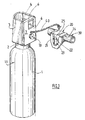
- the Figure 1 represents an embodiment of a support / container assembly, in particular for a medical gas bottle, according to the invention.
- the assembly formed of the gas container 11 and its support 20 schematized in Figure 1 comprises, on the one hand, a gas container 11, namely here a medical gas bottle, and, on the other hand, a container support 20 adapted to and adapted to receive said gas container 11 and support it.
- the gas bottle 11 is formed of a hollow body 1 of cylindrical shape in which is stored a medical gas, in gaseous or liquefied form, for example oxygen, medical grade air, a helium / oxygen, xenon, argon, CO, a NO / nitrogen mixture or any other gas.
- a medical gas in gaseous or liquefied form, for example oxygen, medical grade air, a helium / oxygen, xenon, argon, CO, a NO / nitrogen mixture or any other gas.
- the body 1 of the bottle has, at its upper end, a narrowing forming a neck 2 on which, in a conventional manner, is fixed, for example by screwing, a valve or an integrated pressure regulator valve for controlling the outlet of the gas. the bottle, in particular its flow and possibly its pressure.
- the integrated pressure regulating valve or tap is equipped with one or more control devices, such as a pivoting lever or rotary wheel, and / or one or more indicator devices, such as pressure gauge or flowmeter.
- a protective cover 3 commonly called “cap” comprising a peripheral wall 3 forming a protective enclosure around said tap or tap- regulator.
- the protective cowl 3 is generally attached to the neck 2 of the body 1 of the bottle 11.
- a protective cowl 3 is formed of a rigid metal or plastic material.
- the cowling 3 further comprises an upper recess 4 giving access to the tap or expansion valve and other control members located in the enclosure of the cowling 3.
- a portion of the cowl wall also forms a carrying handle 5 to allow a user to carry and carry the bottle 11.
- Such a protective rollover bottle architecture is notably described by the document EP-A-629812 or EP-A-2586481 ..
- the protective shroud 3 of the gas container 11 comprises a fastener 10 projecting from the surface of the peripheral wall 3, i.e. the fastener 10 projects towards the the outside away from the outer surface of the peripheral wall 6 of the cowling 3, preferably the rear surface 7 of the cowling 3.
- the fastening element 10 here comprises a body 12, of elongated shape, integral with the wall 7 of the protective casing 3 and comprising, at its free end, an enlarged head 13.
- the body 12 of the fixing element 10 is connected to the wall 6 of the cowling 3 by one of its ends and comprises at its opposite end, that is to say its free end , the enlarged head 13 which has a first dimension, in particular a first diameter D1, greater than the second dimension, in particular a second diameter D2, of the body 12 (ie D1> D2).
- the body 12 of the fastening element 10 is cylindrical in shape of second diameter D2, and the enlarged head 12 has the shape of a disk of first diameter D1.
- the enlarged head 13 and the body 12 of the fastening element 10 are coaxial.
- the fastening element 10 is formed in one piece with the rear surface 7 of the wall 6 of the protective casing 3, preferably by molding or the like.
- the fastening element 10 and the protective covering 3 are made of plastic, such as PVC, PE, PET, PP, PMMA, PU ...
- the assembly according to the present invention also comprises a container support 20, illustrated on the Figures 1 , 3 and 4 , which comprises, on the one hand, an attachment system 24 for fixing the container support 20 to a carrier structure 30, such as a wall or a wall, or a rail or a bed of a hospital bed , stretcher, chair or other, and secondly, a housing 22 for receiving the fastening element 10 so as to maintain the bottle 11 secured, that is to say, attached to said support 20.
- a carrier structure 30 such as a wall or a wall, or a rail or a bed of a hospital bed , stretcher, chair or other
- a housing 22 for receiving the fastening element 10 so as to maintain the bottle 11 secured, that is to say, attached to said support 20.
- the container support 20 is attached to a carrier structure 30 of the bed bar type, that is to say of tubular shape having a diameter typically of the order of a few centimeters.
- the attachment system 24 of the container support 20 is of any known type, for example a screw system, with a collet ...
- the container support 20 comprises a housing 22 adapted to and designed to receive the fastening element 10 carried by the protective cover 3 of the gas container 11 so as to secure the container 11 to the support of container 20, when the fixing element 10 is placed in position, that is to say inserted, by the user in the housing 22 of the container support 20.
- the positioning and attachment of the gas bottle 11 to the container support 20 is illustrated by the arrow 40 in Figure 1 .
- the housing 22 has a U-shaped "V" shape open upwards, as shown schematically on the figures 1 , 3 and 4 .
- V U-shaped "V" shape open upwards, as shown schematically on the figures 1 , 3 and 4 .
- a shape facilitates the stowage and suspension of the bottle 11 to the support 20 via a cooperation between the fastening element 10 and the housing 22, the fastening element 10 being housed in the housing 22.
- the housing 22 of the container support 20 comprises one or more holding elements 23, for example two holding elements 23, arranged to retain the fastening element 10 in said housing 22 of the container support 20, preferably two holding members 23 of resilient or flexible material.
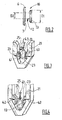
- each holding element 23 may be formed, in all or in part, of a flexible metal blade, for example steel, able to deform slightly during the insertion of the fastening element 10 in the housing 22 , as schematized on the Figures 3 and 4 , that is, in the direction of arrow 43.
- the fixing element 10 can then be housed at the bottom of the housing V or U, and the blades then come resiliently towards each other, in the direction of the arrows 42 of the Figure 4 .
- the housing 22 of the container support 20 comprises a bottom wall 25, preferably a flat wall, and the support elements 23 are arranged externally with respect to this bottom wall 25 and spaced from said bottom wall. 25 so as to "sandwich" the enlarged head 13 of the fastening element 10 between the support members 23 and said bottom wall 25, when the fastening element 10 is inserted (arrow 43) within the housing 22 of the container support 2, as visible in FIG. Figure 4 .
- the container / container support assembly of the invention makes it possible to fix easily, securely and securely the medical gas bottles of different diameters so as to minimize bottle falls and therefore to limit the risk of injury to the user and damage to equipment.
- the present invention is not limited to the medical field and can be used in all fields using gases stored in gas containers, such as bottles, especially in the food, electronic, welding fields. / cutting ...
Landscapes
- Engineering & Computer Science (AREA)
- Mechanical Engineering (AREA)
- General Engineering & Computer Science (AREA)
- Filling Or Discharging Of Gas Storage Vessels (AREA)
- Medical Preparation Storing Or Oral Administration Devices (AREA)
- Details Of Rigid Or Semi-Rigid Containers (AREA)
Abstract
Description
- La présente invention concerne un ensemble récipient/support de récipient comprenant un récipient de gaz, en particulier une bouteille de gaz médical, comprenant un capotage de protection et un support de récipient pour recevoir et porter le récipient de gaz, ledit support comportant un système de fixation pour permettre sa fixation à une structure-porteuse, tel un mur, une paroi, un lit d'hôpital, un brancard ou un fauteuil...
- Les récipients, en particulier les bouteilles de gaz médical, utilisés notamment en milieu hospitalier, à domicile, dans les services ou véhicules d'urgence doivent pouvoir être fixés à différents supports, tel que mur, paroi, lit d'hôpital, brancard, fauteuil...
- Ils doivent donc être dotés d'un système d'accrochage propre porté par le récipient lui-même ou, le cas échéant, il convient d'utiliser un dispositif indépendant permettant son accrochage à un support.
- Ainsi, le document
EP-A-629812 - Le document
EP-A-2586481 propose d'équiper le capotage de protection d'une bouteille de gaz d'une structure d'accrochage pivotante comprenant deux crochets permettant la suspension de la bouteille notamment aux barreaux de lits hospitaliers. - Par ailleurs, on connait aussi des systèmes muraux destinés à être fixés à un support vertical, par exemple un mur ou une paroi, se présentant sous la forme de paniers ou analogues au sein desquels sont insérés les corps des bouteilles en y étant retenus par des sangles ou similaires.
- Cependant, ces systèmes ne sont pas totalement satisfaisants et présentent des inconvénients, à savoir notamment :
- les bouteilles de gaz équipées de capotages de protection à encoche ou crochets d'arrimage ne sont pas fixées de manière stable car elles ne sont pas fixées et peuvent dès lors chuter, notamment si une personne vient par inadvertance heurter la bouteille. Ceci constitue un risque pour l'utilisateur et pour le matériel lui-même. De plus, cela oblige à équiper toutes les bouteilles de capotages de protection spécifique, ce qui peut représenter un cout important.
- les systèmes de type paniers muraux sont encombrants et la manipulation des bouteilles n'est pas toujours aisée. Ainsi, il faut en général soulever la bouteille de gaz pour réaliser son insertion dans un logement du panier, ce qui n'est pas pratique et peut engendrer des blessures pour l'utilisateur.
- Le problème à résoudre est dès lors de proposer un système d'accrochage pour récipient de gaz, en particulier pour bouteille de gaz, en particulier de gaz médical, amélioré, c'est-à-dire ne présentant pas tout ou partie des inconvénients susmentionnés, de manière à minimiser toute situation d'instabilité et à limiter les risques de chutes du récipient, notamment d'une bouteille de gaz, et de blessure pour l'utilisateur.
- La solution de l'invention est un ensemble récipient/support de récipient comprenant un récipient de gaz comprenant un capotage de protection comportant une paroi périphérique, et un support de récipient apte à et conçu pour recevoir et porter ledit récipient de gaz, caractérisé en ce que :
- le capotage de protection du récipient de gaz comprend un élément de fixation faisant saillie à la surface de la paroi périphérique, et
- ledit support de récipient comportant :
- i) un système d'accrochage pour fixer ledit support de récipient à une structure-porteuse, et
- ii) un logement apte à et conçu pour recevoir ledit élément de fixation porté par le capotage de protection du récipient de gaz de manière à solidariser ledit récipient de gaz audit support de récipient, lorsque ledit élément de fixation est positionné dans ledit logement du support de récipient.
- Selon le cas, l'ensemble récipient/support de récipient de l'invention peut comprendre l'une ou plusieurs des caractéristiques techniques suivantes :
- le récipient de gaz est une bouteille de gaz équipée d'un robinet ou d'un robinet-détendeur de gaz autour duquel est agencé le capotage de protection.
- l'élément de fixation fait saillie sur la surface arrière du capotage de protection.
- l'élément de fixation comprend un corps solidaire de la paroi du capotage de protection comprenant, à son extrémité libre, une tête élargie.
- le corps de l'élément de fixation est cylindrique et la tête élargie a une forme de disque.
- l'élément de fixation est formé d'une seule pièce avec le capotage de protection, de préférence par moulage.
- le support de récipient comprend un logement en forme d'encoche.
- le support de récipient comprend un logement en forme d'encoche ouverte vers le haut, lorsque le support de récipient est fixé à une structure-porteuse.
- le logement formant encoche est aménagé dans une pièce en « U » ou en «V».
- le support de récipient comprend un système d'accrochage permettant de fixer ledit support de récipient à une structure-porteuse choisie parmi un rail, un barreau ou une paroi.
- le logement du support de récipient comprend au moins un élément de maintien agencés de manière à retenir l'élément de fixation dans ledit logement du support de récipient, de préférence deux élément de maintien.
- le logement du support de récipient comprend une paroi de fond, ledit au moins un élément de maintien étant agencé de manière espacée de ladite paroi de fond de manière à prendre en sandwich la tête élargie de l'élément de fixation entre ledit au moins un élément de maintien et ladite paroi de fond, lorsque le l'élément de fixation est positionné au sein du logement du support de récipient.
- ledit au moins un élément de maintien comprend une lame ressort.
- le récipient de gaz est une bouteille de gaz, en particulier une bouteille de gaz médical.
- le récipient de gaz est une bouteille d'un gaz médical choisi parmi l'oxygène, l'air, l'air enrichi en oxygène, un mélange N2O/oxygène, hélium/oxygène ou autre.
- La présente invention va maintenant être décrite plus en détail en références aux Figures annexées parmi lesquelles :
- la
Figure 1 représente un mode de réalisation d'un ensemble support/récipient selon l'invention, - la
Figure 2 schématise l'élément de fixation de l'ensemble support/récipient de laFigure 1 , et - les
Figures 3 et 4 schématisent l'insertion de l'élément de fixation de laFigure 2 dans le logement du support de récipient de l'ensemble support/récipient de laFigure 1 . - La
Figure 1 représente un mode de réalisation d'un ensemble support/récipient, en particulier pour bouteille de gaz médical, selon l'invention. - Plus précisément, l'ensemble formé du récipient de gaz 11 et de son support 20 schématisé en
Figure 1 comprend, d'une part, un récipient de gaz 11, à savoir ici une bouteille de gaz médical, et, d'autre part, un support de récipient 20 apte à et conçu pour recevoir ledit récipient de gaz 11 et le supporter. - La bouteille de gaz 11 est formée d'un corps creux 1 de forme cylindrique au sein duquel est stocké un gaz médical, sous forme gazeuse ou liquéfiée, par exemple de l'oxygène, de l'air de qualité médicale, un mélange hélium/oxygène, du xénon, de l'argon, du CO, un mélange NO/azote ou tout autre gaz.
- Le corps 1 de la bouteille comporte, à son extrémité supérieure, un rétrécissement formant un col 2 sur lequel, de façon classique, est fixé, par exemple par vissage, un robinet ou un robinet à détendeur intégré servant à contrôler la sortie du gaz de la bouteille, en particulier son débit et éventuellement sa pression.
- Le robinet ou robinet à détendeur intégré est équipé d'un ou plusieurs organes de commande, tel que levier pivotant ou volant rotatif, et/ou d'un ou plusieurs organes indicateurs, tel que manomètre ou débitmètre.
- Par ailleurs, le robinet ou robinet à détendeur intégré est protégé des chocs et des salissures, notamment de la poussière, par un capotage de protection 3, couramment appelé « chapeau » comportant une paroi périphérique 3 formant une enceinte protectrice autour dudit robinet ou robinet-détendeur. Le capotage de protection 3 est généralement fixé au niveau du col 2 du corps 1 de la bouteille 11. Classiquement, un capotage de protection 3 est formé d'un matériau métallique ou plastique rigide.
- Le capotage 3 comprend en outre un évidement supérieur 4 donnant accès aux robinet ou robinet-détendeur et autres organes de commandes situés dans l'enceinte du capotage 3. Une partie la paroi du capotage forme par ailleurs une poignée 5 de portage pour permettre à un utilisateur de porter et transporter la bouteille 11.
- Une telle architecture de bouteille à capotage de protection est notamment décrite par le document
EP-A-629812 EP-A-2586481 .. - Conformément à la présente invention, le capotage de protection 3 du récipient de gaz 11 comprend un élément de fixation 10 faisant saillie à la surface de la paroi périphérique 3, c'est-à-dire que l'élément de fixation 10 se projette vers l'extérieur en éloignement par rapport à la surface externe de la paroi périphérique 6 du capotage 3, de préférence la surface arrière 7 du capotage 3.
- Comme illustré en
Figure 2 , l'élément de fixation 10 comprend ici un corps 12, de forme allongée, solidaire de la paroi 7 du capotage de protection 3 et comprenant, à son extrémité libre, une tête élargie 13. - En d'autres termes, le corps 12 de l'élément de fixation 10 vient se raccorder à la paroi 6 du capotage 3 par l'une de ses extrémités et comporte à son extrémité opposée, c'est-à-dire son extrémité libre, la tête élargie 13 qui présente une première dimension, en particulier un premier diamètre D1, supérieure à la seconde dimension, en particulier un second diamètre D2, du corps 12 (i.e. D1>D2).
- Dans le mode de réalisation des
Figures 1 et2 , le corps 12 de l'élément de fixation 10 est de forme cylindrique de second diamètre D2, et la tête élargie 12 a une forme de disque de premier diamètre D1. De préférence, la tête élargie 13 et le corps 12 de l'élément de fixation 10 sont coaxiaux. - Avantageusement, l'élément de fixation 10 est formé d'une seule pièce avec la surface arrière 7 de la paroi 6 du capotage de protection 3, de préférence par moulage ou analogue.
- En particulier, l'élément de fixation 10 et le capotage de protection 3 sont en matière plastique, tel que PVC, PE, PET, PP, PMMA, PU...
- Par ailleurs, l'ensemble selon la présente invention comprend également un support de récipient 20, illustré sur les
Figures 1 ,3 et 4 , qui comporte, d'une part, un système d'accrochage 24 permettant de fixer le support de récipient 20 à une structure-porteuse 30, tel qu'un mur ou une paroi, ou un rail ou un barreau de lit d'hôpital, de brancard, de fauteuil ou autre, et d'autre part, un logement 22 destiné à recevoir l'élément de fixation 10 de manière à maintenir la bouteille 11 solidarisée, c'est-à-dire accrochée, audit support 20. - Sur la
Figure 1 , le support de récipient 20 est fixé à une structure-porteuse 30 de type barreau de lit, c'est-à-dire de forme tubulaire ayant un diamètre typiquement de l'ordre de quelques centimètres. - Le système d'accrochage 24 du support de récipient 20 est de tout type connu, par exemple un système à vis, à pince de serrage.....
- Par ailleurs, le support de récipient 20 comprend un logement 22 apte à et conçu pour recevoir l'élément de fixation 10 porté par le capotage de protection 3 du récipient de gaz 11 de manière à solidariser le récipient 11 au support de récipient 20, lorsque l'élément de fixation 10 est mis en position, c'est-à-dire inséré, par l'utilisateur dans le logement 22 du support de récipient 20. Le positionnement et l'accrochage de la bouteille de gaz 11 au support de récipient 20 est illustré par la flèche 40 en
Figure 1 . - De préférence, le logement 22 a une forme d'encoche en « U » en « V » ouverte vers le haut, comme schématisé sur les
figures 1 ,3 et 4 . En effet, une telle forme facilite l'arrimage et la suspension de la bouteille 11 au support 20 via une coopération entre l'élément de fixation 10 et le logement 22, l'élément de fixation 10 venant se loger dans le logement 22. - Par ailleurs, le logement 22 du support de récipient 20 comprend un ou plusieurs éléments de maintien 23, par exemple deux éléments de maintien 23, agencés de manière à retenir l'élément de fixation 10 dans ledit logement 22 du support de récipient 20, de préférence deux éléments de maintien 23 en matériau résilient ou flexible.
- Ainsi, chaque élément de maintien 23 peut être formé, en tout ou en partie, d'une lame métallique flexible, par exemple en acier, apte à se déformer légèrement lors de l'insertion de l'élément de fixation 10 dans le logement 22, comme schématisé sur les
Figures 3 et 4 , c'est-à-dire dans le sens de la flèche 43. - Plus précisément, lorsque l'élément de fixation 10 entre dans le logement 22 (
Fig. 3 ), il vient repousser les lames flexibles 23 dans le sens des flèches 41, de manière à les éloigner l'une de l'autre et, dans le même temps, à permettre le passage du corps 12 cylindrique de l'élément de fixation 10 entre lesdites lames 23. - L'élément de fixation 10 peut alors venir se loger en fond de logement en V ou U, et les lames reviennent alors par résilience l'une vers l'autres, dans le sens les flèches 42 de la
Figure 4 . - Le dégagement de l'élément de fixation 10 et son extraction du logement 22 se fait selon un déplacement contraire.
- En fait, le logement 22 du support de récipient 20 comprend une paroi de fond 25, de préférence une paroi plane, et les éléments de maintiens 23 sont agencés extérieurement par rapport à cette paroi de fond 25 et de manière espacée de ladite paroi de fond 25 de manière à prendre « en sandwich » la tête élargie 13 de l'élément de fixation 10 entre les éléments de maintiens 23 et ladite paroi de fond 25, lorsque le l'élément de fixation 10 est inséré (flèche 43) au sein du logement 22 du support de récipient 2, comme visible en
Figure 4 . - Quel que soit le mode de réalisation considéré, l'ensemble récipient/support de récipient de l'invention permet de fixer facilement, de manière stable et en sécurité les bouteilles de gaz médical de diamètres différents de sorte de minimiser les chutes de bouteille et donc de limiter le risque de blessure pour l'utilisateur et de dommage des équipements.
- Dans tous les cas, la présente invention n'est pas limitée au domaine médical et peut être utilisée dans tous les domaines mettant en oeuvre des gaz stockés dans des récipients de gaz, telles des bouteilles, notamment dans les domaines alimentaire, électronique, du soudage/coupage...
Claims (13)
- Ensemble récipient/support de récipient comprenant :- un récipient de gaz (11) comprenant un capotage de protection (3) comportant une paroi périphérique (3), et- un support de récipient (20) apte à et conçu pour recevoir et porter ledit récipient de gaz (11),
caractérisé en ce que :- le capotage de protection (3) du récipient de gaz (11) comprend un élément de fixation (10) faisant saillie à la surface de la paroi périphérique (3), et- ledit support de récipient (20) comportant :i) un système d'accrochage (24) pour fixer ledit support de récipient (20) à une structure-porteuse (30), etii) un logement (22) apte à et conçu pour recevoir ledit élément de fixation (10) porté par le capotage de protection (3) du récipient de gaz (11) de manière à solidariser ledit récipient de gaz (11) audit support de récipient (20), lorsque ledit élément de fixation (10) est positionné dans ledit logement (22) du support de récipient (20). - Ensemble selon la revendication précédente, caractérisé en ce que le récipient de gaz (11) est une bouteille de gaz équipée d'un robinet ou d'un robinet-détendeur de gaz autour duquel est agencé le capotage de protection (3).
- Ensemble selon l'une des revendications précédentes, caractérisé en ce que l'élément de fixation (10) fait saillie sur la surface arrière (7) du capotage de protection (3).
- Ensemble selon l'une des revendications précédentes, caractérisé en ce que l'élément de fixation (10) comprend un corps (12) solidaire de la paroi (7) du capotage de protection (3) comprenant, à son extrémité libre, une tête élargie (13).
- Ensemble selon l'une des revendications précédentes, caractérisé en ce que le corps (12) de l'élément de fixation (10) est cylindrique et la tête élargie (13) a une forme de disque.
- Ensemble selon l'une des revendications précédentes, caractérisé en ce que l'élément de fixation (10) est formé d'une seule pièce avec le capotage de protection (3), de préférence par moulage.
- Ensemble selon l'une des revendications précédentes, caractérisé en ce que le support de récipient (20) comprend un logement (22) en forme d'encoche.
- Ensemble selon l'une des revendications précédentes, caractérisé en ce que le support de récipient (20) comprend un logement (22) en forme d'encoche ouverte vers le haut, lorsque le support de récipient (20) est fixé à une structure-porteuse (30).
- Ensemble selon l'une des revendications précédentes, caractérisé en ce que le logement (22) formant encoche est aménagé dans une pièce (21) en « U » ou en « V ».
- Ensemble selon l'une des revendications précédentes, caractérisé en ce que le support de récipient (20) comprend un système d'accrochage (24) permettant de fixer ledit support de récipient (20) à une structure-porteuse (30) choisie parmi un rail, un barreau ou une paroi.
- Ensemble selon l'une des revendications précédentes, caractérisé en ce que le logement (22) du support de récipient (20) comprend au moins un élément de maintien (23) agencés de manière à retenir l'élément de fixation (10) dans ledit logement (22) du support de récipient (20), de préférence deux élément de maintien (23).
- Ensemble selon l'une des revendications précédentes, caractérisé en ce que le logement (22) du support de récipient (20) comprend une paroi de fond (25), ledit au moins un élément de maintien (23) étant agencé de manière espacée de ladite paroi de fond (25) de manière à prendre en sandwich la tête élargie (13) de l'élément de fixation (10) entre ledit au moins un élément de maintien (23) et ladite paroi de fond (25), lorsque le l'élément de fixation (10) est positionné au sein du logement (22) du support de récipient (20).
- Ensemble selon l'une des revendications précédentes, caractérisé en ce que ledit au moins un élément de maintien (23) comprend une lame ressort.
Applications Claiming Priority (1)
| Application Number | Priority Date | Filing Date | Title |
|---|---|---|---|
| FR1362596A FR3015001B1 (fr) | 2013-12-13 | 2013-12-13 | Ensemble support et recipient de gaz, telle une bouteille de gaz medical |
Publications (2)
| Publication Number | Publication Date |
|---|---|
| EP2884152A2 true EP2884152A2 (fr) | 2015-06-17 |
| EP2884152A3 EP2884152A3 (fr) | 2015-12-23 |
Family
ID=50482983
Family Applications (1)
| Application Number | Title | Priority Date | Filing Date |
|---|---|---|---|
| EP14191094.3A Withdrawn EP2884152A3 (fr) | 2013-12-13 | 2014-10-30 | Ensemble support et récipient de gaz, telle une bouteille de gaz médical |
Country Status (3)
| Country | Link |
|---|---|
| US (1) | US10323796B2 (fr) |
| EP (1) | EP2884152A3 (fr) |
| FR (1) | FR3015001B1 (fr) |
Cited By (2)
| Publication number | Priority date | Publication date | Assignee | Title |
|---|---|---|---|---|
| CN106704821A (zh) * | 2015-10-22 | 2017-05-24 | 温州深拉防爆设备有限公司 | 一种用拉伸工艺成型的天然气气瓶内胆 |
| CN112572840A (zh) * | 2020-12-14 | 2021-03-30 | 兰州空间技术物理研究所 | 一种电推进系统贮供单元及其制造方法 |
Families Citing this family (2)
| Publication number | Priority date | Publication date | Assignee | Title |
|---|---|---|---|---|
| GB201816795D0 (en) * | 2018-10-16 | 2018-11-28 | Agco Int Gmbh | Senor assembly for vehicle |
| GB2580175A (en) * | 2018-12-24 | 2020-07-15 | Linde Ag | An assembly |
Citations (2)
| Publication number | Priority date | Publication date | Assignee | Title |
|---|---|---|---|---|
| EP0629812A1 (fr) | 1993-06-03 | 1994-12-21 | Compagnie Francaise De Produits Oxygenes | Chapeau de bouteille de gaz |
| EP2586481A1 (fr) | 2011-10-27 | 2013-05-01 | Linde Aktiengesellschaft | Couvercle pour bouchon de valve d'un cylindre de gaz |
Family Cites Families (6)
| Publication number | Priority date | Publication date | Assignee | Title |
|---|---|---|---|---|
| US3370624A (en) * | 1966-02-09 | 1968-02-27 | Roy K. Terrill | Safety device for high pressure gas container |
| US5026016A (en) * | 1989-12-20 | 1991-06-25 | Helm Products, Inc. | Retainer clip |
| US5249702A (en) * | 1992-01-24 | 1993-10-05 | Topp Kathy R | Beverage container and support bracket therefore |
| EP0624752B1 (fr) * | 1993-05-14 | 1996-01-03 | WALTER TOSTO SERBATOI S.p.A. | Récipient protecteur avec joint d'étanchéité pour l'installation soutérraine de réservoirs contenant du gaz liquéfié sous pression |
| CA2640497A1 (fr) * | 2006-01-27 | 2007-08-02 | Medela Holding Ag | Dispositif de fixation pour recipient de drainage |
| US7621565B2 (en) * | 2006-08-14 | 2009-11-24 | Component Concepts International, Llc | Container mounting assembly |
-
2013
- 2013-12-13 FR FR1362596A patent/FR3015001B1/fr not_active Expired - Fee Related
-
2014
- 2014-10-30 EP EP14191094.3A patent/EP2884152A3/fr not_active Withdrawn
- 2014-12-01 US US14/556,262 patent/US10323796B2/en not_active Expired - Fee Related
Patent Citations (2)
| Publication number | Priority date | Publication date | Assignee | Title |
|---|---|---|---|---|
| EP0629812A1 (fr) | 1993-06-03 | 1994-12-21 | Compagnie Francaise De Produits Oxygenes | Chapeau de bouteille de gaz |
| EP2586481A1 (fr) | 2011-10-27 | 2013-05-01 | Linde Aktiengesellschaft | Couvercle pour bouchon de valve d'un cylindre de gaz |
Cited By (2)
| Publication number | Priority date | Publication date | Assignee | Title |
|---|---|---|---|---|
| CN106704821A (zh) * | 2015-10-22 | 2017-05-24 | 温州深拉防爆设备有限公司 | 一种用拉伸工艺成型的天然气气瓶内胆 |
| CN112572840A (zh) * | 2020-12-14 | 2021-03-30 | 兰州空间技术物理研究所 | 一种电推进系统贮供单元及其制造方法 |
Also Published As
| Publication number | Publication date |
|---|---|
| US10323796B2 (en) | 2019-06-18 |
| US20150167897A1 (en) | 2015-06-18 |
| EP2884152A3 (fr) | 2015-12-23 |
| FR3015001A1 (fr) | 2015-06-19 |
| FR3015001B1 (fr) | 2015-12-25 |
Similar Documents
| Publication | Publication Date | Title |
|---|---|---|
| CA2518878C (fr) | Bouteille de gaz medical avec coque protectrice peripherique | |
| EP2860439A2 (fr) | Système d accrochage de bouteille de gaz médical | |
| EP3006809B1 (fr) | Capotage de protection avec système d accrochage pivotant pour bouteille de gaz | |
| EP3044495B1 (fr) | Ensemble comprenant un capotage de protection et une bouteille de gaz avec un dispositif indicateur de pression ou d'autonomie en position haute | |
| EP2918892A1 (fr) | Capotage de protection pour bouteille de gaz avec écran d'affichage électronique en position haute | |
| EP3237077B1 (fr) | Système d'arrimage de sécurité, mousqueton utilisable pour un tel système et ensemble d'arrimage comprenant un tel système. | |
| FR3015001A1 (fr) | Ensemble support et recipient de gaz, telle une bouteille de gaz medical | |
| EP2574361B1 (fr) | Chariot de transport d'une bouteille de gaz médical | |
| EP3531006B1 (fr) | Capotage de protection à système d'accrochage pivotant pour récipient de gaz | |
| EP3260760A1 (fr) | Capotage de protection avec système d'accrochage pivotant à butée d'arrêt pour récipient de gaz | |
| FR3018586A1 (fr) | Capotage de protection pour bouteille de gaz | |
| FR3018585A1 (fr) | Capotage de protection avec poignee de portable a confort ameliore | |
| FR3042584A1 (fr) | Bloc rdi de distribution de gaz avec dispositif indicateur agence au centre du volant de manœuvre | |
| FR3018582A1 (fr) | Capotage de protection avec systeme d’accrochage antiderapant pour recipient de gaz | |
| BE1016100A4 (fr) | Ensemble d'arrimage pour camion. | |
| FR2943010A1 (fr) | Systeme d'attache de securite pour vehicule equipe d'un plancher adapte. | |
| FR2894236A1 (fr) | Chariot devidoir de tuyau admettant une position haute et une position basse | |
| FR3054639A1 (fr) | Ensemble de distribution de gaz | |
| FR3054637A1 (fr) | Capotage de protection pour recipient de gaz a poignee de portage munie d’une etiquette electronique | |
| FR3034492A1 (fr) | Boitier de bouteille de gaz avec cone de guidage |
Legal Events
| Date | Code | Title | Description |
|---|---|---|---|
| PUAI | Public reference made under article 153(3) epc to a published international application that has entered the european phase |
Free format text: ORIGINAL CODE: 0009012 |
|
| 17P | Request for examination filed |
Effective date: 20141030 |
|
| AK | Designated contracting states |
Kind code of ref document: A2 Designated state(s): AL AT BE BG CH CY CZ DE DK EE ES FI FR GB GR HR HU IE IS IT LI LT LU LV MC MK MT NL NO PL PT RO RS SE SI SK SM TR |
|
| AX | Request for extension of the european patent |
Extension state: BA ME |
|
| PUAL | Search report despatched |
Free format text: ORIGINAL CODE: 0009013 |
|
| AK | Designated contracting states |
Kind code of ref document: A3 Designated state(s): AL AT BE BG CH CY CZ DE DK EE ES FI FR GB GR HR HU IE IS IT LI LT LU LV MC MK MT NL NO PL PT RO RS SE SI SK SM TR |
|
| AX | Request for extension of the european patent |
Extension state: BA ME |
|
| RIC1 | Information provided on ipc code assigned before grant |
Ipc: F17C 13/08 20060101AFI20151113BHEP |
|
| R17P | Request for examination filed (corrected) |
Effective date: 20160623 |
|
| RBV | Designated contracting states (corrected) |
Designated state(s): AL AT BE BG CH CY CZ DE DK EE ES FI FR GB GR HR HU IE IS IT LI LT LU LV MC MK MT NL NO PL PT RO RS SE SI SK SM TR |
|
| GRAP | Despatch of communication of intention to grant a patent |
Free format text: ORIGINAL CODE: EPIDOSNIGR1 |
|
| GRAJ | Information related to disapproval of communication of intention to grant by the applicant or resumption of examination proceedings by the epo deleted |
Free format text: ORIGINAL CODE: EPIDOSDIGR1 |
|
| STAA | Information on the status of an ep patent application or granted ep patent |
Free format text: STATUS: THE APPLICATION HAS BEEN WITHDRAWN |
|
| INTG | Intention to grant announced |
Effective date: 20181030 |
|
| 18W | Application withdrawn |
Effective date: 20181029 |
|
| INTC | Intention to grant announced (deleted) |