EP2884345A2 - Hebelfeder für uhrwerk - Google Patents
Hebelfeder für uhrwerk Download PDFInfo
- Publication number
- EP2884345A2 EP2884345A2 EP14197604.3A EP14197604A EP2884345A2 EP 2884345 A2 EP2884345 A2 EP 2884345A2 EP 14197604 A EP14197604 A EP 14197604A EP 2884345 A2 EP2884345 A2 EP 2884345A2
- Authority
- EP
- European Patent Office
- Prior art keywords
- jumper
- head
- jumping
- necklace
- movement
- Prior art date
- Legal status (The legal status is an assumption and is not a legal conclusion. Google has not performed a legal analysis and makes no representation as to the accuracy of the status listed.)
- Granted
Links
Images





Classifications
-
- G—PHYSICS
- G04—HOROLOGY
- G04B—MECHANICALLY-DRIVEN CLOCKS OR WATCHES; MECHANICAL PARTS OF CLOCKS OR WATCHES IN GENERAL; TIME PIECES USING THE POSITION OF THE SUN, MOON OR STARS
- G04B11/00—Click devices; Stop clicks; Clutches
- G04B11/006—Clutch mechanism between two rotating members with transfer of movement in only one direction (free running devices)
- G04B11/008—Clutch mechanism between two rotating members with transfer of movement in only one direction (free running devices) with friction members, e.g. click springs or jumper
-
- G—PHYSICS
- G04—HOROLOGY
- G04B—MECHANICALLY-DRIVEN CLOCKS OR WATCHES; MECHANICAL PARTS OF CLOCKS OR WATCHES IN GENERAL; TIME PIECES USING THE POSITION OF THE SUN, MOON OR STARS
- G04B11/00—Click devices; Stop clicks; Clutches
-
- G—PHYSICS
- G04—HOROLOGY
- G04B—MECHANICALLY-DRIVEN CLOCKS OR WATCHES; MECHANICAL PARTS OF CLOCKS OR WATCHES IN GENERAL; TIME PIECES USING THE POSITION OF THE SUN, MOON OR STARS
- G04B19/00—Indicating the time by visual means
- G04B19/24—Clocks or watches with date or week-day indicators, i.e. calendar clocks or watches; Clockwork calendars
Definitions
- the invention relates to a jumper for a watch movement.
- the invention also relates to a clock mechanism comprising such a jumper.
- the invention also relates to a watch movement comprising such a mechanism or such a jumper.
- the invention also relates to a timepiece, in particular a watch, comprising such a movement or such a mechanism or such a jumper.
- the document EP1746470 discloses an indexing pin of a date disk which is constituted by a spring lever on which is fixed a spout at one end of the lever.
- the lever-spring is movable in rotation along a pivot axis located at an end opposite that of the spout, and the latter is not movable relative to the lever-spring.
- the lever-spring can not restore the potential energy that it has accumulated, and it follows therefore a stable equilibrium state problematic because the disc or the organ, that the jumper is intended to index, is not in a defined position, for example a defined position of indication of a date.
- the document EP1785783 discloses an indexing jumper of a date disc whose operation is similar to that of the aforementioned patent application. A difference comes from the architecture of the jumper which consists here of a separate lever and a wire-spring.
- the lever is movable in rotation about a pivot axis located at a first end of the lever, and a second end of the lever comprises a projection serving as a nose which is pressed against the toothing of the date disk under the effect wire spring.
- Such a construction does not cancel the risk of no return to the rest position of the jumping spout.
- the document JP2004184259 discloses a construction in which the spout of the indexing spider is movable in translation. This configuration does not cancel the risk of blocking the date disc between two dates due to a single degree of freedom of movement of the jumping spout.
- the patent application JP2008197036 also describes a jumper movable in translation by the implementation of a flexible guide.
- This architecture makes it possible, in principle, to obtain the same moments applied to the date disk regardless of its direction of rotation, but does not make it possible to cancel the range of rotation of the date disc in which the spout and the disc of the calendars can be in stable equilibrium.
- the known jumpers generally comprise a projection in the form of spout which bears against two consecutive teeth of a wheel under the effect of a first return spring.
- the wheel is held precisely in an angular position stable and determined.
- this wheel is rotated over more than a half-angular step, one of its teeth leads the beak of the saltire until the beak reaches the head of said tooth, then the latter is elastically biased against of the successive tooth so that the wheel takes a complete angular step and is positioned again in a stable angular position.
- the object of the invention is to provide a jumper to overcome the disadvantages mentioned above and to improve the jumpers known from the prior art.
- the invention proposes a jumper minimizing the risks, or even avoiding the risks, of occurrence of situations in which the member with which the jumper cooperates is in a non-planned and / or undesirable stable position.
- a jumper according to the invention comprises a jumper body, a jumping head, a first connecting element of the jumping head on the jumper body, the first connecting element allowing a movement of the jumping head relative to the jumper body. jumper, including a rotation movement.
- a clock mechanism according to the invention is defined by claim 13.
- An embodiment of a watch mechanism is defined by claim 14.
- a watch movement according to the invention is defined by claim 15.
- a timepiece according to the invention is defined by claim 16.
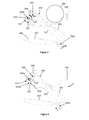
- a first embodiment of a timepiece 299, in particular a watch, in particular a wristwatch, is described hereinafter with reference to FIG. figure 2 .
- the timepiece comprises a watch movement 298.
- the watch movement comprises a watch mechanism 297, for example a calendar mechanism.
- the clock mechanism comprises a jumper 201 and a frame 1 on which is mounted the jumper, in particular a body 210 of the jumper.
- the mechanism further comprises a wheel or disk 205 in cooperation with the jumper and at least one drive device 260 of the wheel or disk, in particular a drive device of the wheel or disk which is distinct from the jumper.
- the driving device may for example be in the form of a wheel or a drive finger which is kinematically connected to the drive train of a basic movement.
- the driving device may also be in the form of a correction mechanism, such as a correction wheel or a rocker.
- the jumper allows to index in position, particularly angularly in position, an element 205 such as a wheel or a cam or a display member, in particular a display member of a magnitude related to time such as a disc of calendars.
- the first embodiment of the jumper 201 comprises the body 210 of jumper, a head or a beak 203 of jumper, a first connecting element 292 of the jumping head on the body of jumper.
- the first link member 292 allows movement of the jumper head 203 relative to the jumper body 210.
- the movement may in particular include a rotational movement, such as a movement consisting of a rotational movement and a translational movement.
- the first connecting element can only allow rotational movement as shown on the Figures 2 to 11 .
- the jumper body comprises a second connecting element 293 of the jumper body.
- the second connecting element 293 allows a movement of the body 210 of the jumper relative to the frame 1 on which the body 210 of the jumper is intended to be mounted.
- the movement may include a rotational movement and / or a translational movement such as a movement consisting of a rotational movement and a translational movement.
- the second connecting element can only allow a rotational movement as shown on the Figures 2 to 11 .
- a first element 200 for returning the jumping head to a first position is preferably adapted to return the jumping head to the first position in a first direction and in a second direction, in particular according to the trigonometric and anti-trigonometric directions shown in FIG. the figures.
- the jumbo body delimited by a first end 281 and a second end 282, comprises, in this embodiment, mainly a main arm 202, a first auxiliary arm 209 and a second auxiliary arm 220.
- the main arm is dimensionally stable or almost indeformable in conventional use of the jumper.
- the first auxiliary arm 209 is part of the first return element 200 of the jumper head in a first position relative to the jumper body, in particular relative to the main arm.
- the first return element allows in particular elastically recall the jumping head in the first position relative to the jumper body, in particular relative to the main arm.
- the first position is represented on the figures 2 , 3 and 9 .
- the first auxiliary arm and / or the first return element is for example a flexible arm integral with the rest of the body, in particular with the main arm.
- the first auxiliary arm is for example linked to the rest of the body, in particular to the main arm at the second end 282 of the body.
- the second auxiliary arm 220 constitutes one or is part of a second element 220 for returning the jumper body, in particular the main arm, in a second position relative to the frame.
- the second return element in particular allows to elastically recall the jumper body, in particular the main arm, in the second position relative to the frame.
- the second position is represented in particular figures 3 and 9 .
- the second auxiliary arm and / or the second return element is for example a flexible arm integral with the rest of the body, in particular with the main arm.
- the second auxiliary arm is for example linked to the rest of the body, in particular to the main arm at the second end 282 of the body.
- the second connecting element 293 preferably comprises a pin or an axis 203b, respectively a bore, provided on the jumper, in particular at the second end 282 of the body, and intended to cooperate with a bore, respectively a pin or an axis. , planned on the frame.
- the second return element makes it possible to return the jumper around the axis 203b in rotation towards its second position.
- the second auxiliary arm takes for example support on an element 206, including a stop, provided on the frame. In the second position, the first end 281 of the jumper is positioned so that the head of the jumper engages in conformations 250 of the member 205 with which it is intended to cooperate.
- the second auxiliary arm can generate a couple resistive M2 relative to the axis 203b and thus allow maintaining the angular position of the member as shown in FIG. figure 3 .
- the first connecting element 292 preferably comprises a pin or an axis 202a integral with the jumper body, in particular at the first end 281 of the body, which is intended to cooperate with a bore 203a formed on the jumping head.
- the structure allows for a pivot connection of the head on the body of the jumper around an axis 292a.
- the first biasing element makes it possible to rotate the head around the axis 292a in rotation towards its first position.
- the head comprises two flanks 231 and 232. These two flanks form an angle, including an obtuse angle. The two flanks are intended to come into contact with the conformations, in particular against the teeth, of the element 205 that the jumper is intended to index in position.
- the head also comprises a cam flank 230, in particular a cam-shaped cam flank capable of cooperating with a cam follower such as a peg, a pin or more generally an axis 204, arranged on the first auxiliary arm 209. , especially at the end of the first auxiliary arm.
- the cam follower is biased against the cam flank by an elastic member constituted by the first auxiliary arm 209.
- the first element 200 for returning the head comprises the axis 204 and the cam flank 230.
- the first return element is provided to generate a resistive torque M3 relative to the axis 292a and to hold the head in position in a certain angular position.
- the resilient member includes the first auxiliary arm 209 and the cam follower or cam flank.
- the cam follower may be provided on the first auxiliary arm, in particular at one end of the first auxiliary arm, and the cam flank may be provided on the head.
- the cam flank may be provided on the first auxiliary arm, in particular at one end of the first auxiliary arm, and the cam follower may be provided on the head.
- the cam flank can be shaped like a vee.
- the jumper 201 comprises a lever-spring on which is mounted in rotation the jumper head.
- the jumper head has a bidirectional mode of operation.
- this head cancels the angular range of non-return in the rest position of the jumper irrespective of the direction of rotation of the element that the jumper is intended to index.
- Such a solution is particularly well suited to a date disk that can be moved in two directions of correction.
- a first training phase of the element 205 as shown in FIG. figure 4 when the latter is run over an angular range of 0 ° to a value of the order of a quarter of an angular pitch the head is rotated in the anti-trigonometric direction only about the axis 293a under the actuating a flank 250a of a tooth 250 of the element 205 on the flank 232 of the head.
- the jumper body is thus moved away from the second position against the action of the second return element.
- the jumper head may first be rotated in a first direction of rotation only about the axis 292a when a tooth 250 leads the jumping head.
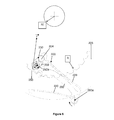
- a second training phase of the element 205 as shown in FIG. figure 5 when the latter is conducted over an angular range of a value of the order of a quarter of an angular pitch to a value of the order of one half an angular step, the head is also rotated by the contact of the tooth 250 on the side 232 in the anti-trigonometric direction about the axis 293a so that its side 230 arms the first auxiliary arm 209 via the cam follower 204. The head is thus removed from the first position against the action of the first return element.
- the head 203 reaches the top of the tooth as shown in FIG.
- figure 6 it is oriented relative to the tooth 250 so that the reaction force of the tooth crown on the jumping head is not directed towards the axis of pivoting of the element 205. More particularly, the force of reaction F does not pass through the circle whose radius Rf is defined by the guide radius R of the element 205 as well as by the coefficient of friction between the date disc and its guide surface, more particularly by the product of the radius R guide and sinus arc-tangent coefficient of friction between the date disk and its guide surface. Moreover, the position of the head relative to the axis 293a is unstable so that the passage from one side to the other of the tooth takes place instantaneously thanks to the energy stored in the first elastic auxiliary arm 209 which is released.
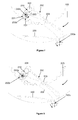
- a third training phase of the element 205 as shown in FIG. figure 7 restitution or return to the rest position of the first elastic auxiliary arm 209 induces the rotation of the head 203 in the trigonometric direction about the axis 293a, which allows it to cross the top of the tooth 250.
- the flank 231 the head then leads a flank of the tooth 250 of the element 205.
- the head is rotatable along the axes 292a and 293a in the counterclockwise direction.
- the head is again in a stable position relative to the axis 292a. It is again rotatable only around the axis 293a until the body of the jumper is against a stop 207 or the flanks 231 and 232 of the head are against respective flanks of the teeth 250 as shown in FIG. figure 9 .
- the operating principle of the jumper is the same for a rotation in the trigonometric direction of the element 205, the sidewall 230 of the head 203 is also shaped to arm the first elastic auxiliary arm 209 via the pin 204 when the head rotates in the counterclockwise direction as shown in figure 10 .
- the actions of the flanks 231 and 232 are then reversed.
- this jumper in particular the jumping head, may have a mode of operation which is more easily broken down into two or three distinct phases of rotation of the element 205.
- the head can thus be rotated in a first direction of rotation. vis-à-vis the axes respectively 292a and 293a since a tooth of the element 205 leads the head, until the latter substantially reaches the top of said tooth.
- the head can then be rotated in a second direction of rotation with respect to the axes 292a and 293a respectively, provided that the head passes through the top of the tooth head of the element 205, until the jumper reaches its rest position.
- the pin 204 can be rotatable about a third axis of rotation 204a, as shown in FIG. figure 11 .
- the pin can roll on the cam flank rather than slide against it.
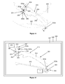
- a second embodiment of a timepiece 399, in particular a watch, in particular a wristwatch, is described hereinafter with reference to FIG. figure 12 .
- the timepiece comprises a watch movement 398.
- the watch movement comprises a watch mechanism 397, for example a calendar mechanism.
- the clock mechanism comprises a jumper 301 and a frame 1 on which is mounted the jumper, in particular a body 310 of the jumper.
- the mechanism further comprises a wheel or disk 305 in cooperation with the jumper and a drive device 360 of the wheel or disk, in particular a drive device of the wheel or disk which is separate from the jumper.
- the driving device may for example be in the form of a wheel or a drive finger which is kinematically connected to the drive train of a basic movement.
- the driving device may also be in the form of a correction mechanism, such as a correction wheel or a rocker.
- the jumper makes it possible to index in position, in particular angularly in position, an element 305 such as a wheel or a cam or else a display member, in particular a display member of a magnitude related to time such that a disc of calendars.
- the second embodiment of the jumper 301 comprises the jumper body 310, a jumper head 303 or a jumper spout, a first connecting element 392 of the jumper head on the jumper body.
- the first link member 392 allows movement of the jumper head 303 relative to the jumper body 310.
- the movement may include a rotational movement such as a movement consisting of a rotational movement and a translational movement.
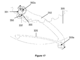
- the first connecting element can only allow a rotational movement as shown on the Figures 12 to 17 .
- An element of the first embodiment and an element of the second embodiment having the same or similar functions carry references having numbers of tens and identical units.
- the hundreds digit is a "2" for the element reference of the first embodiment and the hundreds digit is a "3" for the element reference of the second embodiment.
- the second embodiment differs mainly from the first embodiment in that the first return element of the jumping head in the first position relative to the jumper body is adapted to return the jumping head to the first position in a first direction. , the first position being defined by a first abutment 350 integral with the jumper body.
- the first return element comprises a spring blade 300 integral with the jumping head, respectively integral with the jumper body, cooperating by contact with a second stop 350 provided on the jumping body, respectively on the jumping head.
- the first and second stops are made by one and the same stop.
- the jumper head has a unidirectional operating mode so as to eliminate the range of no return in the rest position of the jumper for a single direction of rotation of the element 305 with which it cooperates.
- the jumper allows to index in position this element 305.
- the jumper does not have a first auxiliary arm.
- the first return element of the jumper head in the first position relative to the jumper body here comprises a spring blade 300 or a spring.
- This spring is for example secured to the head 303 by welding.
- This spring is pre-armed by a stop or a pin 350 attached to the main arm 302. The spring takes effect against the stop.
- the stop 350 also makes it possible to stop the head in a predetermined position which corresponds to the stop position of the head against the stop. There can of course be two stops, one to support the spring and one to stop the head in a predefined position.
- this jumper For a single direction of rotation of the element 305, for example a rotation in the anti-trigonometric direction as represented in FIGS. Figures 15 to 17 , the operating principle of this jumper is identical to that of the first embodiment.
- This jumper also has a mode of operation that can be broken down into two, three, or four phases of rotation of the date disc.
- the figure 14 illustrates the saltire at rest.
- the figure 15 represents the rotation of the head in the anti-trigonometric direction with respect to the axes 392a and 393a respectively under the actuation of the flank 350a of the tooth 350.
- figure 16 represents the head positioned substantially at the top of the tooth. Its positioning is then unstable under the effect of the spring 300.
- figure 17 illustrates the head once it has crossed the top of the tooth; it is then rotatable in the counterclockwise direction with respect to the axes 292a and 293a, respectively.
- the jumper body may be movable in translation along an axis substantially parallel to the plane of the frame of the mechanism or the watch movement.
- the jumper head may have a single or bidirectional operating mode.
- the first connecting element is preferably a guide element which provides a pivot connection between the jumping head and the jumper body.
- the first return element and / or the second return element may be in the form of guides or flexible hinges.
- a jumper according to the invention makes it possible to minimize the risks, or even to avoid the risks, of occurrence of situations in which the jumper is in an equilibrium position while it is not in the rest position.
- the jumper may be part of a clock mechanism, including a calendar mechanism.
- the jumper cooperates with a wheel or disc, in particular cooperates by contact with a wheel or a disc, in particular cooperates by contact with a toothing of a wheel or disc.
- the jumper thus indexes in position the wheel or the disc.
- the wheel or the disc more generally the mechanism, is actuable via a drive device 260, 360 separate from the jumper.
- the drive device may for example be in the form of a drive wheel which is kinematically connected to the drive train of a basic movement.
- the driving device may also be in the form of a correction mechanism, such as a correction wheel or a rocker.
- the disk may be a calendar disk which may be rotated via its toothing by the driver.
- the head of the jumper is in permanent contact with the wheel or the disc which it indexes in position, in particular in permanent contact with a toothing of the wheel or the disc. This is particularly the case when the wheel or disc is not actuated by the driving device.
- the jumping head is biased by a first resilient return member against the wheel or disk.
- the return of the mechanical energy of the return element can participate in driving the wheel or disk.
- the jumping head is arranged in such a way that the reaction force produced between it and the toothing of the disk or the wheel to be indexed is oriented to prevent a jamming of the jumping head at the top of a tooth. of the wheel or disc or to avoid the existence of a position of equilibrium of the jumping head at the top of a tooth of the wheel or the disc, in particular when the wheel or disc is actuated by a device of training.
- the term "jumper” means a body terminated by a head provided with two inclined planes that support, by elastic return, between the vertices and / or the flanks of two consecutive teeth of a wheel to maintain it in a certain position.
Landscapes
- Physics & Mathematics (AREA)
- General Physics & Mathematics (AREA)
- Electromechanical Clocks (AREA)
- Moving Of Heads (AREA)
- Golf Clubs (AREA)
- Electric Clocks (AREA)
- Toys (AREA)
Priority Applications (1)
| Application Number | Priority Date | Filing Date | Title |
|---|---|---|---|
| EP14197604.3A EP2884345B1 (de) | 2013-12-13 | 2014-12-12 | Hebelfeder für uhrwerk |
Applications Claiming Priority (2)
| Application Number | Priority Date | Filing Date | Title |
|---|---|---|---|
| EP13197199 | 2013-12-13 | ||
| EP14197604.3A EP2884345B1 (de) | 2013-12-13 | 2014-12-12 | Hebelfeder für uhrwerk |
Publications (3)
| Publication Number | Publication Date |
|---|---|
| EP2884345A2 true EP2884345A2 (de) | 2015-06-17 |
| EP2884345A3 EP2884345A3 (de) | 2016-06-22 |
| EP2884345B1 EP2884345B1 (de) | 2020-11-11 |
Family
ID=49759171
Family Applications (1)
| Application Number | Title | Priority Date | Filing Date |
|---|---|---|---|
| EP14197604.3A Active EP2884345B1 (de) | 2013-12-13 | 2014-12-12 | Hebelfeder für uhrwerk |
Country Status (4)
| Country | Link |
|---|---|
| US (1) | US9292001B2 (de) |
| EP (1) | EP2884345B1 (de) |
| JP (1) | JP6494266B2 (de) |
| CN (1) | CN104714395B (de) |
Cited By (1)
| Publication number | Priority date | Publication date | Assignee | Title |
|---|---|---|---|---|
| WO2018115014A3 (fr) * | 2016-12-23 | 2018-10-18 | Sa De La Manufacture D'horlogerie Audemars Piguet & Cie | Composant monolithique flexible pour pièce d'horlogerie |
Families Citing this family (2)
| Publication number | Priority date | Publication date | Assignee | Title |
|---|---|---|---|---|
| US11550265B2 (en) * | 2017-11-02 | 2023-01-10 | Rolex Sa | Drive device for horology calendar system |
| EP3772673B1 (de) * | 2019-08-08 | 2022-04-06 | ETA SA Manufacture Horlogère Suisse | Indexierungselement für uhren |
Citations (4)
| Publication number | Priority date | Publication date | Assignee | Title |
|---|---|---|---|---|
| JP2004184259A (ja) | 2002-12-04 | 2004-07-02 | Seiko Instruments Inc | カレンダ機構付き時計 |
| EP1746470A1 (de) | 2005-07-20 | 2007-01-24 | Breitling AG | Uhr mit Kalendermechanismus |
| EP1785783A1 (de) | 2005-11-11 | 2007-05-16 | ETA SA Manufacture Horlogère Suisse | Jahreskalendermechanismus für Uhrwerk |
| JP2008197036A (ja) | 2007-02-15 | 2008-08-28 | Seiko Instruments Inc | ジャンパ構造体並びにこれを備えたカレンダ機構及びカレンダ機構付き時計 |
Family Cites Families (14)
| Publication number | Priority date | Publication date | Assignee | Title |
|---|---|---|---|---|
| CH338766A (de) | 1957-04-30 | 1959-05-31 | Guebelin Soehne | Schalteinrichtung für Uhrwerk |
| CH339129A (fr) * | 1957-12-16 | 1959-06-15 | Longines Montres Comp D | Pièce d'horlogerie à quantièmes instantanés |
| CH470703A (fr) * | 1965-06-14 | 1967-01-31 | Montres Perret Et Berthoud Sa | Pièce d'horlogerie comprenant un mécanisme de quantième à saut instantané |
| US3482391A (en) * | 1968-06-25 | 1969-12-09 | Selig Golen | Day and date calendar clock mechanism |
| EP0404467B1 (de) * | 1989-06-19 | 1994-12-14 | Seiko Epson Corporation | Zeitmessvorrichtung |
| CN2470857Y (zh) * | 2001-02-28 | 2002-01-09 | 杭州手表有限公司 | 手表日历瞬跳机构 |
| EP1536298A1 (de) * | 2003-11-25 | 2005-06-01 | Montres Breguet S.A. | Kalendermechanismus mit Mitführungs- und Korrektionsvorrichtungen für zwei Anzeiger |
| DE602005001798T8 (de) * | 2004-05-14 | 2008-08-28 | Rolex Sa | Jährlicher Kalendermechanismus für Uhrwerk |
| EP2180383B1 (de) * | 2008-10-24 | 2012-01-25 | ETA SA Manufacture Horlogère Suisse | Hilfsvorrichtung zur Positionshaltung einer Datumsanzeigescheibe für Uhrwerk |
| JP5311559B2 (ja) * | 2009-01-23 | 2013-10-09 | セイコーインスツル株式会社 | 2つの日車を有するカレンダ機構付き時計 |
| EP2428855B1 (de) * | 2010-09-08 | 2019-07-03 | Rolex S.A. | Uhrenteil, das eine Vorrichtung zur Anzeige von festgelegten Zeiträumen umfasst |
| CH703823B1 (fr) * | 2010-09-23 | 2014-12-15 | Patek Philippe Sa Geneve | Bascule à cliquet, mécanisme d'entraînement pas à pas comportant une telle bascule et pièce d'horlogerie comportant un tel mécanisme. |
| JP5688997B2 (ja) | 2011-03-13 | 2015-03-25 | セイコーインスツル株式会社 | レトログラード表示機構及びこれを備えた時計 |
| FR2973122B1 (fr) * | 2011-03-23 | 2014-01-03 | Samep Montres Emile Pequignet | Mecanisme d'actionnement pour mouvement horloger et mouvement horloger correspondant |
-
2014
- 2014-12-08 JP JP2014247530A patent/JP6494266B2/ja active Active
- 2014-12-09 US US14/564,259 patent/US9292001B2/en active Active
- 2014-12-12 CN CN201410769013.5A patent/CN104714395B/zh active Active
- 2014-12-12 EP EP14197604.3A patent/EP2884345B1/de active Active
Patent Citations (4)
| Publication number | Priority date | Publication date | Assignee | Title |
|---|---|---|---|---|
| JP2004184259A (ja) | 2002-12-04 | 2004-07-02 | Seiko Instruments Inc | カレンダ機構付き時計 |
| EP1746470A1 (de) | 2005-07-20 | 2007-01-24 | Breitling AG | Uhr mit Kalendermechanismus |
| EP1785783A1 (de) | 2005-11-11 | 2007-05-16 | ETA SA Manufacture Horlogère Suisse | Jahreskalendermechanismus für Uhrwerk |
| JP2008197036A (ja) | 2007-02-15 | 2008-08-28 | Seiko Instruments Inc | ジャンパ構造体並びにこれを備えたカレンダ機構及びカレンダ機構付き時計 |
Cited By (1)
| Publication number | Priority date | Publication date | Assignee | Title |
|---|---|---|---|---|
| WO2018115014A3 (fr) * | 2016-12-23 | 2018-10-18 | Sa De La Manufacture D'horlogerie Audemars Piguet & Cie | Composant monolithique flexible pour pièce d'horlogerie |
Also Published As
| Publication number | Publication date |
|---|---|
| JP6494266B2 (ja) | 2019-04-03 |
| CN104714395A (zh) | 2015-06-17 |
| JP2015114324A (ja) | 2015-06-22 |
| EP2884345A3 (de) | 2016-06-22 |
| US9292001B2 (en) | 2016-03-22 |
| US20150168915A1 (en) | 2015-06-18 |
| CN104714395B (zh) | 2019-06-07 |
| EP2884345B1 (de) | 2020-11-11 |
Similar Documents
| Publication | Publication Date | Title |
|---|---|---|
| EP3483663B1 (de) | Antriebsvorrichtung für kalendersystem einer uhr | |
| EP1953611B1 (de) | Uhr, die einen Antriebsmechanismus einer Vorrichtung zur Anzeige einer mit der Zeit zusammenhängenden Größe umfasst | |
| EP3144743B1 (de) | Uhrwerk mit einem datumskorrektur-mechanismus | |
| EP3612896B1 (de) | Verriegelungsvorrichtung fuer uhrwerkmechanismus | |
| EP3059643B1 (de) | Uhrmechanismus | |
| EP2073076A1 (de) | Betätigungsmechanismus eines weckers | |
| EP3602202B1 (de) | Vorrichtung zur einstellung von funktionen einer uhr | |
| EP1617305A1 (de) | Arretiervorrichtung bei der Zeigerstellung einer Uhr mit einem Tourbillon | |
| EP2884345B1 (de) | Hebelfeder für uhrwerk | |
| EP3489766B1 (de) | Mechanismus zur korrektur einer bewegungsfunktion einer uhr | |
| EP3173877A1 (de) | Kalendersystem für uhr | |
| EP4270114B1 (de) | Vorrichtung zum auswählen und betätigen mehrerer funktionen eines uhrwerks | |
| EP3584643B1 (de) | Augenblicklich schaltende steuervorrichtung für datumsanzeige von uhren | |
| CH713209B1 (fr) | Mécanisme d'affichage pour pièce d'horlogerie. | |
| EP2124112A1 (de) | Uhrmechanismus und diesen Mechanismus umfassendes Modul | |
| CH708338B1 (fr) | Mécanisme correcteur pas-à-pas. | |
| FR2973122A1 (fr) | Mecanisme d'actionnement pour mouvement horloger et mouvement horloger correspondant | |
| EP1558971B1 (de) | Kalendarmechanismus für uhrwerk | |
| EP3353607B1 (de) | Mechanismus zum positionieren eines zahnrads in einem uhrwerk | |
| EP4312088B1 (de) | Vorrichtung mit versenkbarem finger zum betätigen eines uhrwerkmechanismus | |
| EP1960846B1 (de) | Uhrwerk | |
| EP4462192B1 (de) | Anzeigevorrichtung für uhrwerk | |
| CH706341A2 (fr) | Mécanisme de mise à l'heure et de remontage pour pièce d'horlogerie. | |
| CH716774B1 (fr) | Dispositif horloger de couplage et d'indexation. | |
| EP4312087B1 (de) | Jahreskalendermechanismus für uhrwerk |
Legal Events
| Date | Code | Title | Description |
|---|---|---|---|
| PUAI | Public reference made under article 153(3) epc to a published international application that has entered the european phase |
Free format text: ORIGINAL CODE: 0009012 |
|
| 17P | Request for examination filed |
Effective date: 20141212 |
|
| AK | Designated contracting states |
Kind code of ref document: A2 Designated state(s): AL AT BE BG CH CY CZ DE DK EE ES FI FR GB GR HR HU IE IS IT LI LT LU LV MC MK MT NL NO PL PT RO RS SE SI SK SM TR |
|
| AX | Request for extension of the european patent |
Extension state: BA ME |
|
| PUAL | Search report despatched |
Free format text: ORIGINAL CODE: 0009013 |
|
| AK | Designated contracting states |
Kind code of ref document: A3 Designated state(s): AL AT BE BG CH CY CZ DE DK EE ES FI FR GB GR HR HU IE IS IT LI LT LU LV MC MK MT NL NO PL PT RO RS SE SI SK SM TR |
|
| AX | Request for extension of the european patent |
Extension state: BA ME |
|
| RIC1 | Information provided on ipc code assigned before grant |
Ipc: G04B 11/00 20060101AFI20160519BHEP Ipc: G04B 19/24 20060101ALI20160519BHEP |
|
| STAA | Information on the status of an ep patent application or granted ep patent |
Free format text: STATUS: REQUEST FOR EXAMINATION WAS MADE |
|
| R17P | Request for examination filed (corrected) |
Effective date: 20161222 |
|
| RBV | Designated contracting states (corrected) |
Designated state(s): AL AT BE BG CH CY CZ DE DK EE ES FI FR GB GR HR HU IE IS IT LI LT LU LV MC MK MT NL NO PL PT RO RS SE SI SK SM TR |
|
| STAA | Information on the status of an ep patent application or granted ep patent |
Free format text: STATUS: EXAMINATION IS IN PROGRESS |
|
| 17Q | First examination report despatched |
Effective date: 20190308 |
|
| RIN1 | Information on inventor provided before grant (corrected) |
Inventor name: FLEURY, CHRISTIAN |
|
| GRAP | Despatch of communication of intention to grant a patent |
Free format text: ORIGINAL CODE: EPIDOSNIGR1 |
|
| STAA | Information on the status of an ep patent application or granted ep patent |
Free format text: STATUS: GRANT OF PATENT IS INTENDED |
|
| INTG | Intention to grant announced |
Effective date: 20200520 |
|
| GRAS | Grant fee paid |
Free format text: ORIGINAL CODE: EPIDOSNIGR3 |
|
| GRAA | (expected) grant |
Free format text: ORIGINAL CODE: 0009210 |
|
| STAA | Information on the status of an ep patent application or granted ep patent |
Free format text: STATUS: THE PATENT HAS BEEN GRANTED |
|
| AK | Designated contracting states |
Kind code of ref document: B1 Designated state(s): AL AT BE BG CH CY CZ DE DK EE ES FI FR GB GR HR HU IE IS IT LI LT LU LV MC MK MT NL NO PL PT RO RS SE SI SK SM TR |
|
| REG | Reference to a national code |
Ref country code: GB Ref legal event code: FG4D Free format text: NOT ENGLISH |
|
| REG | Reference to a national code |
Ref country code: CH Ref legal event code: EP |
|
| REG | Reference to a national code |
Ref country code: AT Ref legal event code: REF Ref document number: 1334083 Country of ref document: AT Kind code of ref document: T Effective date: 20201115 |
|
| REG | Reference to a national code |
Ref country code: CH Ref legal event code: NV Representative=s name: MOINAS AND SAVOYE SARL, CH |
|
| REG | Reference to a national code |
Ref country code: DE Ref legal event code: R096 Ref document number: 602014072224 Country of ref document: DE |
|
| REG | Reference to a national code |
Ref country code: IE Ref legal event code: FG4D Free format text: LANGUAGE OF EP DOCUMENT: FRENCH |
|
| REG | Reference to a national code |
Ref country code: NL Ref legal event code: MP Effective date: 20201111 |
|
| REG | Reference to a national code |
Ref country code: AT Ref legal event code: MK05 Ref document number: 1334083 Country of ref document: AT Kind code of ref document: T Effective date: 20201111 |
|
| PG25 | Lapsed in a contracting state [announced via postgrant information from national office to epo] |
Ref country code: FI Free format text: LAPSE BECAUSE OF FAILURE TO SUBMIT A TRANSLATION OF THE DESCRIPTION OR TO PAY THE FEE WITHIN THE PRESCRIBED TIME-LIMIT Effective date: 20201111 Ref country code: RS Free format text: LAPSE BECAUSE OF FAILURE TO SUBMIT A TRANSLATION OF THE DESCRIPTION OR TO PAY THE FEE WITHIN THE PRESCRIBED TIME-LIMIT Effective date: 20201111 Ref country code: NO Free format text: LAPSE BECAUSE OF FAILURE TO SUBMIT A TRANSLATION OF THE DESCRIPTION OR TO PAY THE FEE WITHIN THE PRESCRIBED TIME-LIMIT Effective date: 20210211 Ref country code: PT Free format text: LAPSE BECAUSE OF FAILURE TO SUBMIT A TRANSLATION OF THE DESCRIPTION OR TO PAY THE FEE WITHIN THE PRESCRIBED TIME-LIMIT Effective date: 20210311 Ref country code: GR Free format text: LAPSE BECAUSE OF FAILURE TO SUBMIT A TRANSLATION OF THE DESCRIPTION OR TO PAY THE FEE WITHIN THE PRESCRIBED TIME-LIMIT Effective date: 20210212 |
|
| PG25 | Lapsed in a contracting state [announced via postgrant information from national office to epo] |
Ref country code: BG Free format text: LAPSE BECAUSE OF FAILURE TO SUBMIT A TRANSLATION OF THE DESCRIPTION OR TO PAY THE FEE WITHIN THE PRESCRIBED TIME-LIMIT Effective date: 20210211 Ref country code: AT Free format text: LAPSE BECAUSE OF FAILURE TO SUBMIT A TRANSLATION OF THE DESCRIPTION OR TO PAY THE FEE WITHIN THE PRESCRIBED TIME-LIMIT Effective date: 20201111 Ref country code: IS Free format text: LAPSE BECAUSE OF FAILURE TO SUBMIT A TRANSLATION OF THE DESCRIPTION OR TO PAY THE FEE WITHIN THE PRESCRIBED TIME-LIMIT Effective date: 20210311 Ref country code: SE Free format text: LAPSE BECAUSE OF FAILURE TO SUBMIT A TRANSLATION OF THE DESCRIPTION OR TO PAY THE FEE WITHIN THE PRESCRIBED TIME-LIMIT Effective date: 20201111 Ref country code: PL Free format text: LAPSE BECAUSE OF FAILURE TO SUBMIT A TRANSLATION OF THE DESCRIPTION OR TO PAY THE FEE WITHIN THE PRESCRIBED TIME-LIMIT Effective date: 20201111 Ref country code: LV Free format text: LAPSE BECAUSE OF FAILURE TO SUBMIT A TRANSLATION OF THE DESCRIPTION OR TO PAY THE FEE WITHIN THE PRESCRIBED TIME-LIMIT Effective date: 20201111 |
|
| REG | Reference to a national code |
Ref country code: LT Ref legal event code: MG9D |
|
| PG25 | Lapsed in a contracting state [announced via postgrant information from national office to epo] |
Ref country code: HR Free format text: LAPSE BECAUSE OF FAILURE TO SUBMIT A TRANSLATION OF THE DESCRIPTION OR TO PAY THE FEE WITHIN THE PRESCRIBED TIME-LIMIT Effective date: 20201111 |
|
| PG25 | Lapsed in a contracting state [announced via postgrant information from national office to epo] |
Ref country code: LT Free format text: LAPSE BECAUSE OF FAILURE TO SUBMIT A TRANSLATION OF THE DESCRIPTION OR TO PAY THE FEE WITHIN THE PRESCRIBED TIME-LIMIT Effective date: 20201111 Ref country code: RO Free format text: LAPSE BECAUSE OF FAILURE TO SUBMIT A TRANSLATION OF THE DESCRIPTION OR TO PAY THE FEE WITHIN THE PRESCRIBED TIME-LIMIT Effective date: 20201111 Ref country code: SK Free format text: LAPSE BECAUSE OF FAILURE TO SUBMIT A TRANSLATION OF THE DESCRIPTION OR TO PAY THE FEE WITHIN THE PRESCRIBED TIME-LIMIT Effective date: 20201111 Ref country code: SM Free format text: LAPSE BECAUSE OF FAILURE TO SUBMIT A TRANSLATION OF THE DESCRIPTION OR TO PAY THE FEE WITHIN THE PRESCRIBED TIME-LIMIT Effective date: 20201111 Ref country code: CZ Free format text: LAPSE BECAUSE OF FAILURE TO SUBMIT A TRANSLATION OF THE DESCRIPTION OR TO PAY THE FEE WITHIN THE PRESCRIBED TIME-LIMIT Effective date: 20201111 Ref country code: EE Free format text: LAPSE BECAUSE OF FAILURE TO SUBMIT A TRANSLATION OF THE DESCRIPTION OR TO PAY THE FEE WITHIN THE PRESCRIBED TIME-LIMIT Effective date: 20201111 |
|
| REG | Reference to a national code |
Ref country code: DE Ref legal event code: R097 Ref document number: 602014072224 Country of ref document: DE |
|
| PG25 | Lapsed in a contracting state [announced via postgrant information from national office to epo] |
Ref country code: MC Free format text: LAPSE BECAUSE OF FAILURE TO SUBMIT A TRANSLATION OF THE DESCRIPTION OR TO PAY THE FEE WITHIN THE PRESCRIBED TIME-LIMIT Effective date: 20201111 Ref country code: DK Free format text: LAPSE BECAUSE OF FAILURE TO SUBMIT A TRANSLATION OF THE DESCRIPTION OR TO PAY THE FEE WITHIN THE PRESCRIBED TIME-LIMIT Effective date: 20201111 |
|
| REG | Reference to a national code |
Ref country code: BE Ref legal event code: MM Effective date: 20201231 |
|
| PLBE | No opposition filed within time limit |
Free format text: ORIGINAL CODE: 0009261 |
|
| STAA | Information on the status of an ep patent application or granted ep patent |
Free format text: STATUS: NO OPPOSITION FILED WITHIN TIME LIMIT |
|
| 26N | No opposition filed |
Effective date: 20210812 |
|
| PG25 | Lapsed in a contracting state [announced via postgrant information from national office to epo] |
Ref country code: IT Free format text: LAPSE BECAUSE OF FAILURE TO SUBMIT A TRANSLATION OF THE DESCRIPTION OR TO PAY THE FEE WITHIN THE PRESCRIBED TIME-LIMIT Effective date: 20201111 Ref country code: IE Free format text: LAPSE BECAUSE OF NON-PAYMENT OF DUE FEES Effective date: 20201212 Ref country code: LU Free format text: LAPSE BECAUSE OF NON-PAYMENT OF DUE FEES Effective date: 20201212 Ref country code: NL Free format text: LAPSE BECAUSE OF FAILURE TO SUBMIT A TRANSLATION OF THE DESCRIPTION OR TO PAY THE FEE WITHIN THE PRESCRIBED TIME-LIMIT Effective date: 20201111 Ref country code: AL Free format text: LAPSE BECAUSE OF FAILURE TO SUBMIT A TRANSLATION OF THE DESCRIPTION OR TO PAY THE FEE WITHIN THE PRESCRIBED TIME-LIMIT Effective date: 20201111 |
|
| PG25 | Lapsed in a contracting state [announced via postgrant information from national office to epo] |
Ref country code: SI Free format text: LAPSE BECAUSE OF FAILURE TO SUBMIT A TRANSLATION OF THE DESCRIPTION OR TO PAY THE FEE WITHIN THE PRESCRIBED TIME-LIMIT Effective date: 20201111 Ref country code: ES Free format text: LAPSE BECAUSE OF FAILURE TO SUBMIT A TRANSLATION OF THE DESCRIPTION OR TO PAY THE FEE WITHIN THE PRESCRIBED TIME-LIMIT Effective date: 20201111 |
|
| PG25 | Lapsed in a contracting state [announced via postgrant information from national office to epo] |
Ref country code: IS Free format text: LAPSE BECAUSE OF FAILURE TO SUBMIT A TRANSLATION OF THE DESCRIPTION OR TO PAY THE FEE WITHIN THE PRESCRIBED TIME-LIMIT Effective date: 20210311 Ref country code: TR Free format text: LAPSE BECAUSE OF FAILURE TO SUBMIT A TRANSLATION OF THE DESCRIPTION OR TO PAY THE FEE WITHIN THE PRESCRIBED TIME-LIMIT Effective date: 20201111 Ref country code: MT Free format text: LAPSE BECAUSE OF FAILURE TO SUBMIT A TRANSLATION OF THE DESCRIPTION OR TO PAY THE FEE WITHIN THE PRESCRIBED TIME-LIMIT Effective date: 20201111 Ref country code: CY Free format text: LAPSE BECAUSE OF FAILURE TO SUBMIT A TRANSLATION OF THE DESCRIPTION OR TO PAY THE FEE WITHIN THE PRESCRIBED TIME-LIMIT Effective date: 20201111 |
|
| PG25 | Lapsed in a contracting state [announced via postgrant information from national office to epo] |
Ref country code: MK Free format text: LAPSE BECAUSE OF FAILURE TO SUBMIT A TRANSLATION OF THE DESCRIPTION OR TO PAY THE FEE WITHIN THE PRESCRIBED TIME-LIMIT Effective date: 20201111 |
|
| PG25 | Lapsed in a contracting state [announced via postgrant information from national office to epo] |
Ref country code: BE Free format text: LAPSE BECAUSE OF NON-PAYMENT OF DUE FEES Effective date: 20201231 |
|
| P01 | Opt-out of the competence of the unified patent court (upc) registered |
Effective date: 20230601 |
|
| REG | Reference to a national code |
Ref country code: CH Ref legal event code: U11 Free format text: ST27 STATUS EVENT CODE: U-0-0-U10-U11 (AS PROVIDED BY THE NATIONAL OFFICE) Effective date: 20260101 |
|
| PGFP | Annual fee paid to national office [announced via postgrant information from national office to epo] |
Ref country code: GB Payment date: 20251229 Year of fee payment: 12 |
|
| PGFP | Annual fee paid to national office [announced via postgrant information from national office to epo] |
Ref country code: FR Payment date: 20251230 Year of fee payment: 12 |
|
| PGFP | Annual fee paid to national office [announced via postgrant information from national office to epo] |
Ref country code: DE Payment date: 20251231 Year of fee payment: 12 |
|
| PGFP | Annual fee paid to national office [announced via postgrant information from national office to epo] |
Ref country code: CH Payment date: 20260101 Year of fee payment: 12 |