EP2886012B1 - Systeme de fixation pour des meubles - Google Patents
Systeme de fixation pour des meubles Download PDFInfo
- Publication number
- EP2886012B1 EP2886012B1 EP14197964.1A EP14197964A EP2886012B1 EP 2886012 B1 EP2886012 B1 EP 2886012B1 EP 14197964 A EP14197964 A EP 14197964A EP 2886012 B1 EP2886012 B1 EP 2886012B1
- Authority
- EP
- European Patent Office
- Prior art keywords
- pin
- sliding channel
- eyelet
- shelf
- axis
- Prior art date
- Legal status (The legal status is an assumption and is not a legal conclusion. Google has not performed a legal analysis and makes no representation as to the accuracy of the status listed.)
- Not-in-force
Links
- 230000037431 insertion Effects 0.000 claims description 24
- 238000003780 insertion Methods 0.000 claims description 24
- 238000004873 anchoring Methods 0.000 description 11
- 230000008878 coupling Effects 0.000 description 3
- 238000010168 coupling process Methods 0.000 description 3
- 238000005859 coupling reaction Methods 0.000 description 3
- 239000000463 material Substances 0.000 description 2
- 229920003023 plastic Polymers 0.000 description 2
- 239000004033 plastic Substances 0.000 description 2
- 230000000284 resting effect Effects 0.000 description 2
- 238000000465 moulding Methods 0.000 description 1
- 230000002035 prolonged effect Effects 0.000 description 1
Images




Classifications
-
- A—HUMAN NECESSITIES
- A47—FURNITURE; DOMESTIC ARTICLES OR APPLIANCES; COFFEE MILLS; SPICE MILLS; SUCTION CLEANERS IN GENERAL
- A47B—TABLES; DESKS; OFFICE FURNITURE; CABINETS; DRAWERS; GENERAL DETAILS OF FURNITURE
- A47B96/00—Details of cabinets, racks or shelf units not covered by a single one of groups A47B43/00 - A47B95/00; General details of furniture
- A47B96/06—Brackets or similar supporting means for cabinets, racks or shelves
- A47B96/066—Supporting means received within an edge of the shelf
-
- F—MECHANICAL ENGINEERING; LIGHTING; HEATING; WEAPONS; BLASTING
- F16—ENGINEERING ELEMENTS AND UNITS; GENERAL MEASURES FOR PRODUCING AND MAINTAINING EFFECTIVE FUNCTIONING OF MACHINES OR INSTALLATIONS; THERMAL INSULATION IN GENERAL
- F16B—DEVICES FOR FASTENING OR SECURING CONSTRUCTIONAL ELEMENTS OR MACHINE PARTS TOGETHER, e.g. NAILS, BOLTS, CIRCLIPS, CLAMPS, CLIPS OR WEDGES; JOINTS OR JOINTING
- F16B12/00—Jointing of furniture or the like, e.g. hidden from exterior
- F16B12/10—Jointing of furniture or the like, e.g. hidden from exterior using pegs, bolts, tenons, clamps, clips, or the like
- F16B12/12—Jointing of furniture or the like, e.g. hidden from exterior using pegs, bolts, tenons, clamps, clips, or the like for non-metal furniture parts, e.g. made of wood, of plastics
- F16B12/26—Jointing of furniture or the like, e.g. hidden from exterior using pegs, bolts, tenons, clamps, clips, or the like for non-metal furniture parts, e.g. made of wood, of plastics using snap-action elements
-
- F—MECHANICAL ENGINEERING; LIGHTING; HEATING; WEAPONS; BLASTING
- F16—ENGINEERING ELEMENTS AND UNITS; GENERAL MEASURES FOR PRODUCING AND MAINTAINING EFFECTIVE FUNCTIONING OF MACHINES OR INSTALLATIONS; THERMAL INSULATION IN GENERAL
- F16B—DEVICES FOR FASTENING OR SECURING CONSTRUCTIONAL ELEMENTS OR MACHINE PARTS TOGETHER, e.g. NAILS, BOLTS, CIRCLIPS, CLAMPS, CLIPS OR WEDGES; JOINTS OR JOINTING
- F16B12/00—Jointing of furniture or the like, e.g. hidden from exterior
- F16B12/10—Jointing of furniture or the like, e.g. hidden from exterior using pegs, bolts, tenons, clamps, clips, or the like
- F16B12/12—Jointing of furniture or the like, e.g. hidden from exterior using pegs, bolts, tenons, clamps, clips, or the like for non-metal furniture parts, e.g. made of wood, of plastics
- F16B12/14—Jointing of furniture or the like, e.g. hidden from exterior using pegs, bolts, tenons, clamps, clips, or the like for non-metal furniture parts, e.g. made of wood, of plastics using threaded bolts or screws
Definitions
- This invention relates to a fastening system for attaching a shelf or a bracket to an item of furniture or the like.
- an item of furniture comprises vertical uprights and top and bottom horizontal panels, mainly one lower and one upper panel, which bound the structure of the item of furniture, and may comprise one or more horizontal intermediate panels known as shelves, or brackets.
- a shelf may be supported with vertical movement on supporting means projecting from the upright, or the shelf may be inserted into suitable spaces made along the walls of the upright by performing a movement which is horizontal and perpendicular to the upright.
- a pin tensioned by an eccentric device a pin is fixed in the vertical upright, the head of the pin is shaped and intended to be inserted in the seat formed laterally in the shelf which has to be attached.
- a hole perpendicular to the axis of the seat is also formed in the shelf and through this a securing bush of an eccentric type is inserted.
- the bush has a lower opening suitable for housing the head of the pin. The bush is caused to rotate by means of a suitable tool, engaging the head of the pin, which in turn generates tension between the upright and the shelf.
- Another solution in the state of the art provides for the presence of a grub screw located within a bush in one of the two parts and a tie rod located in the second part in such a way that screwing up the grub screw places tension on the tie bar, thus securing the two parts in a perpendicular position.
- a tool must be used to screw up or secure the device, tie bar or other in one of the two parts which have to be secured onto for example the upright, and possibly a different tool must be used to secure the eccentric device or grub screw located in the second of the two parts which are to be attached, that is the shelf, in order to attach the shelf and the upright together.
- a fastening system comprising a supporting element and a separate locking device is known from GB1204071A .
- Panels provided with a hole with an eyelet and a coupling member intended to be inserted in the holes for mutually coupling the panels are known from US 7,021,019 .
- the technical problem underlying this invention is that of providing a fastening system for attaching a shelf to an upright of an item of furniture or the like which overcomes the limitations stated with reference to the cited known art.
- one object of the invention is to provide a fastening system through which fastening operations can be simplified, at the same time making them quicker.
- the system according to the invention permits repeated assembly and dismaritling of the item of furniture, guaranteeing at the same time that the shelves will be firmly secured to the uprights even on subsequent assembly.
- any damage to the shelves during assembly is limited or eliminated.
- the system according to the invention is also particularly dimensionally stable over time and strong.
- the system is also suitable for use with supporting elements other than shelves or brackets, for example components for suspending clothing, ties, or even vertical panels, etc.
- the system is suitable for the attachment of two furniture components which have to be located perpendicularly with respect to each other.
- the figures show a fastening system 100 for attaching a shelf 4, or other supporting element in an item of furniture, to a structure of an item of furniture.
- fastening system 100 is suitable for attaching horizontal shelves to vertical uprights, or the sides of an item of furniture, or in general to attach together elements of furniture which are located perpendicularly to one another.
- Fastening system 100 may be used to attach a supporting element other than a shelf, such as for example elements for hanging clothes, ties or trousers, non-horizontal shelves, vertical panels, or also furniture elements located at an angle other than 90° to each other, to a structure of an item of furniture.
- a supporting element other than a shelf such as for example elements for hanging clothes, ties or trousers, non-horizontal shelves, vertical panels, or also furniture elements located at an angle other than 90° to each other, to a structure of an item of furniture.
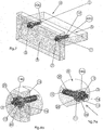
- Fastening system 100 comprises a supporting element 1, shown in greater detail in Figures 1A and 1B , 5A , 6A, 7A , 7B , and a locking device 2, illustrated in greater detail in Figures 2 and 9 , which are intended to act together with a attachment pin to attach a shelf to an upright, as will be more particularly explained below.
- Supporting element 1, attachment pin 3 and locking device 2 are separate bodies which are associated to secure a supporting element to a structure of an item of furniture.
- Locking device 2 may be removably associated with supporting element 1 to lock attachment pin 3 and supporting element 1 together. By removing locking device 2 it is possible to move attachment pin and supporting element 1 with respect to each other, as will be clarified below.
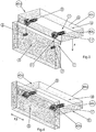
- Supporting element 1 and locking device 2 are intended to be associated with a shelf 4, as may better be seen in Figure 8 , to attach shelf 4 to the uprights of an item of furniture, an upright 5 being partly illustrated in Figures 3 and 5-8 .
- the vertical axis is indicated below as the Z axis, the longitudinal axis as the X axis and the transverse or horizontal axis as the Y axis.
- shelf 4 is rectangular in shape and is bounded by two opposite longitudinal edges 42a, 42b intended to face uprights 5 of the structure of the item of furniture to which shelf 4 must be attached when in use, and two opposing transverse edges 42c, 42d, one of which is intended to constitute the visible edge of shelf 4, and two opposing base surfaces, an upper base surface S which faces upwards when shelf 4 is in use and is usually intended to constitute the supporting surface of shelf 4, and an opposing lower base surface S'.
- Two holes 43, 43' provided in positions which are longitudinally apart (along longitudinal axis X) and intended to receive two different supporting elements 1, 1' to attach them to shelf 4, as may be seen in Figures 4-6 , and as more particularly explained below, are defined in each of longitudinal edges 42a, 42b of shelf 4.
- each hole 43, 43' comprises a seat 43a, 43'a defined in longitudinal edge 42a or 42b of shelf 4 and is intended to house a head 11 of supporting element 1 and a longitudinal seat 43b, 43'b extending from corresponding seat 43a, 43'a in the direction of the transverse axis Y in shelf 4 intended to house an anchoring element 10 of supporting element 1, as will be more particularly explained below.
- opening 44 is provided in the surface of the lower base S' of shelf 4, that is the base surface opposite the intended supporting surface S, in such a way that it is not readily visible during use of the item of furniture obtained with shelf 4.
- a number of holes other than two, for example one or three, depending upon the dimensions and/or the weight and/or the final orientation of the shelf which has to be attached and/or the final use of the supporting element, are provided on the longitudinal edge or on both longitudinal edges of shelf 4.
- the longitudinal distance between the holes is also selected on the basis of the dimensions and/or weight of the shelf or in general of the supporting element.
- Uprights 5 are usually flat in shape and extend along a vertical axis Z and a longitudinal axis X, and are provided with pairs of hooking holes suitably positioned along vertical axis Z of the upright in order to attach shelves 4 at different desired heights on upright 5.
- Each pair of hooking holes comprises a first and a second hole 51, 51' at a distance from each other in the direction of longitudinal axis X.
- Each attachment pin 3, 3' comprises a shank 3b, 3'b intended to be inserted into a hooking hole 51, 51' of upright 5 and a head 3a, 3'a having larger radial dimensions than corresponding shank 3b, 3'b and positioned in such a way that when in use it faces shelf 4 to engage a corresponding supporting element 1, 1' to attach shelf 4 to upright 5, as will be more particularly described below.
- the attachment pins are provided with hooking elements to lock the pins firmly in the hooking holes.
- hooking holes 51, 51' of each pair of holes are positioned in the same longitudinal axis X at a desired mutual distance which depends on the dimensions of upright 5 and shelf 4.
- shelf 4 may be positioned horizontally, that is its supporting surface S is horizontal, that is it lies in a plane parallel to the XY plane, but in other versions holes 51, 51' of the same pair of holes are positioned at different heights with respect to vertical axis Z mutually spaced in relation to longitudinal axis X, the supporting surface S of shelf 4 lying in a plane transverse to the XY plane.
- Supporting element 1 is intended to be inserted in a hole 43 formed in shelf 4 and comprising a head 11 intended to be housed in seat 43a formed in longitudinal edge 42b of shelf 4 and an anchoring member 10 intended to be inserted into longitudinal seat 43b to stably attach supporting element 1 to shelf 4.
- Anchoring member 10 is provided with anchoring elements shaped as fins 20 extending upon anchoring member 10 in a radial direction and intended to increase friction between anchoring member 10 and the wall of longitudinal seat 43b to stably attach supporting element 1 in hole 43.
- anchoring member 10 may provide anchoring elements other than fins, for example pressure or threaded anchoring elements, etc.
- Supporting element 1 and hole 43 are mutually dimensioned in such a way that supporting element 1 is housed in hole 43 in such a way that it cannot be seen.
- Head 11 of supporting element 1 comprises an internally hollow body 21 bounded by an end wall 22 in which anchoring element 10 is inserted, a front edge 23 and a side edge 24 shaped in such a way as to define a slot 12.
- Slot 12 is provided with an entry opening 13 to allow head 3a of pin 3 to enter/leave slot 12 and the sliding channel 14 extending from entry opening 13 along an axis of insertion Z to an end portion 14a of sliding channel 14 and intended to slidably house head 3a of pin 3 when shelf 4 is inserted onto the upright.
- Walls 14b of the sliding channel are inclined with respect to the vertical axis of insertion Z by an angle ⁇ of between 0.5° and 15° so as to define an entry opening 13 having a length D considered along longitudinal axis X which is longer than the length of sliding channel 14 in order to facilitate entry of pin 3 into slot 12.
- slot 12 comprises a first eyelet 15 and a second eyelet 25 located on opposite sides with respect to each other of sliding channel 14 in relation to longitudinal axis X and communicating with sliding channel 14.
- First and second eyelets 15, 25 are shaped in such a way as to house head 3a of pin 3 when shelf 4 is inserted onto uprights 5, as will be more particularly described below.
- First eyelet 15 and second eyelet 25 are located preferably symmetrically with respect to sliding channel 14, that is with respect to vertical axis of insertion Z, and at a distance from the latter of "t" considered along longitudinal axis X of between 0.5 and 10 mm, preferably between 2 and 4 mm, depending upon the dimensions of head 11.
- each eyelet 15 or 25 there is a pair of facing edges 41, 42 and 41', 42' respectively which are intended to define entry opening "A" from sliding channel 14 into each eyelet 15 or 25, entry opening "A" of each eyelet 15 or 25 having dimensions which are smaller than the eyelet itself.
- the extension of entry opening "A" along vertical axis Z for each eyelet 15 or 25 is less than the extension of eyelet 15, 25 along vertical axis Z.
- each pair of edges 41, 42 and 41', 42' are dimensioned in such a way as to define an entry opening "A" having dimensions which in particular when considered along vertical axis of insertion Z are smaller than the dimensions of shank 3b of pin 3 and constitute means for retaining pin 3 in each eyelet 15 or 25.
- the edges of each pair of edges 41, 42 and 41', 42' are resiliently deformable in such a way as to allow pin 3 to move in sliding channel 14 into one of eyelet 15, 25 and constitute resilient retaining means for pin 3 in eyelet 15 or 25.
- slot 12 of supporting element 1 is provided with a single eyelet at a distance from axis of insertion Z.
- This distance makes it possible to prevent pin 3 from accidentally escaping from slot 12 through lateral movement along axis of insertion Z, as more particularly explained below.
- a front opening 26 adjacent to sliding channel 14 having a width "d1" is defined in front edge 23 of head 11, which is smaller than or equivalent to the width of sliding channel 14 in such a way as to allow shank 3b of pin 3 but not its head 3a to pass, thus preventing pin 3 from undesirably escaping from sliding channel 14 through movements along transverse axis Y.
- front openings 26' defined in front edge 23 in relation to eyelets 15, 25 have smaller dimensions than the dimensions of eyelets 15, 25 so as to allow shank 3b of pin 3 but not its head 3a to pass through, thus preventing the pin from undesirably escaping by movements along transverse axis Y.
- Inner wall 28 of front edge 23, that is the part facing sliding channel 14, is inclined at an angle of inclination ⁇ of between 0.5° and 25°, preferably between 1° and 6°, with respect to the direction of axis of insertion Z.
- Locking device 2 comprises a base portion 30 shaped in such a way as to shapingly coupling with opening 44 provided in lower base surface S' of shelf 4 in such a way as to cover it, and a locking element 31 extending from the base portion in a direction perpendicular to base portion 30 and intended to interact with pin 3 and supporting element 1 to lock pin 3 in eyelet 15 or 25 of supporting element 1, as will be more particularly described below.
- Locking element 31 comprises a base 31a defined in base portion 30 of locking device 2 and a projection 31b opposite base 31a and designed to interact with pin 3 to lock it in one of eyelets 15 or 25 provided in supporting element 1, as will be more particularly described below.
- Locking element 31 has the shape of a wedge thinning from base 31a to projection 31b in such a way as to facilitate the insertion of locking element 31 into slot 12, as more particularly described below.
- a first and a second supporting element 1, 1' are anchored in a shelf 4, inserting them into corresponding holes 43, 43' and anchoring members 10, 10' in longitudinal seats 43b, 43'b of corresponding holes 43, 43', as illustrated in Figure 4 .
- a first and a second attachment pin 3, 3' are inserted into first hole 51 and second hole 51' respectively of a pair of hooking holes defined in upright 5 with their corresponding heads 3a, 3a' facing shelf 4 which has to be attached, as illustrated in Figure 3 .
- shelf 4 is offered up to upright 5 in such a way as to place slots 12, 12' of supporting elements 1, 1' adjacent to pins 3, 3', as illustrated in Figure 5 .
- Pin 3 or 3' slides into the sliding channel 14, 14' of slot 12 or 12' along axis of insertion Z being guided in this movement by inner wall 28 of front edge 23 and being progressively drawn towards shelf 4 by the inner wall, that is in the direction of transverse axis Y.
- shelf 4 continues to be pushed in the direction of arrow F, pin 3 or 3' is pressed against end portion 14a, 14'a of sliding channel 14 or 14', as illustrated in Figures 6 and 10b .
- End portion 14a, 14'a forms an end stop element for pin 3, 3' in sliding channel 14.
- entry opening A has smaller dimensions than the dimensions of shank 3b of the pin, therefore as the shank passes through edges 41, 42 or 41', 42' deform resiliently from the resting position illustrated in Figure 10a to a deformed position to allow shank 3b to pass through.
- edges 41, 42 or 41', 42' respectively can return to their initial resting position and constitute resilient retaining means for resiliently retaining pin 3 in eyelets 15 or 25, preventing it from accidentally escaping by lateral movement along longitudinal axis X.
- the pin in order to be able to escape from eyelet 15 or 25 the pin must overcome the resilient retaining force generated by edges 41, 42 or 41' 42' respectively. In addition to this the walls of the eyelet retain the pin, preventing it from moving along axis of insertion Z.
- Edges 41, 42, 41', 42' act as resilient retaining means for pin 3 preventing accidental movements of shelf 4 with respect to upright 5 during assembly.
- shelf 4 is therefore stable with respect to upright 5, that is the conformation of supporting element 1 prevents shelf 4 from accidentally falling.
- the inherent weight of shelf 4 helps to keep it attached to upright 5.
- the conformation of supporting element 1, 1' and in particular inner wall 28 and/or the walls of the eyelets and edges 41, 42 or 41', 42' respectively make it possible for attachment pin 3, 3' to be held in eyelets 15, 15' or 25, 25' and accidental falls of shelf 4 are avoided.
- inner wall 28 makes it possible to keep pin 3 under tension, preventing it from accidentally escaping before pin 3 is inserted in eyelets 15 or 25, by lateral movement along transverse axis Y.
- eyelets 15, 25 are at a distance "t" from sliding channel 14, this makes it possible to prevent pin 3 from escaping from eyelets 15, 25 by lateral movement along axis of insertion Z, and this, as mentioned, makes it possible to help assembly operations because there is no need to support the shelf when it is in locked position B.
- Locking device 2 is moved in the direction of inserting arrow F3 in Figures 8 and 9 , in such a way that locking element 31 is progressively inserted into sliding channel 14 of slot 12.
- Locking device 2, 2' is pressed into slot 12 until locking element 31 is inserted into sliding channel 14 and comes into contact with pin 3b in such a way that it is positioned between pin 3 and sliding channel 14 and in fact locks pin 3 in eyelet 15 or 25, as may be seen in Figure 9 , attachment configuration B'.
- Slot 12 and/or locking element 31 are mutually dimensioned in such a way that when in attachment configuration B' projection 31b is at a distance from end portion 14a and in such a way as to generate locking of more than 2/3 of a circle with eyelets 15 or 25, preventing pin 3 from escaping from eyelets 15 or 25.
- Locking element 31 is inserted into slot 12 in such a way as to close off entry opening A to eyelets 15, 25, in fact preventing the pin from escaping from eyelet 15 or 25 in which it is housed.
- locking element 31 will vary according to the thickness of shelf 4 and/or the dimensions of slot 12.
- the operator will first extract locking device 2, possibly the help of a screwdriver or similar device, to disconnect locking device 2 from hole 43.
- the operator will gain access to base 30 of locking device 2 which is positioned in opening 44 and by levering with a screwdriver or other tool will raise base 30 of opening 44 and remove locking device 2 from hole 43.
- shelf 4 in order to move it in the direction of longitudinal axis X in order to remove pins 3, 3' from the eyelets, moving them into sliding channel 14 and finally moving shelf 4 along axis of insertion Z in a direction opposite to that indicated by arrow F, causing pin 3 to escape from slot 12 and in fact disconnecting shelf 4 and upright 5.
- shelf 4 is mounted at 90° with respect to upright 5, however other orientations can be achieved with the system according to the invention.
- the direction of insertion is parallel to vertical axis Z and sliding channel 14, and is therefore vertical, although in other versions not shown supporting element 1 is positioned in hole 43 in such a way that sliding channel 14 extends along a transverse direction of insertion with respect to vertical axis Z.
- the pins may be attached to the shelf which has to be attached and supporting element 1 may be attached to the upright.
- locking element 2 is made of plastics material and supporting element 1 is made as a single piece by moulding plastics material.
Landscapes
- Engineering & Computer Science (AREA)
- General Engineering & Computer Science (AREA)
- Mechanical Engineering (AREA)
- Assembled Shelves (AREA)
- Chairs Characterized By Structure (AREA)
- Orthopedics, Nursing, And Contraception (AREA)
- Lock And Its Accessories (AREA)
- Furniture Connections (AREA)
- Connection Of Plates (AREA)
Claims (13)
- Système de fixation (100) pour fixer une étagère (4) ou un autre élément de support d'un article d'ameublement sur une structure d'un article d'ameublement (5) comprenant :une goupille de fixation (3, 3') ;un élément de support (1) prévu pour être inséré dans un trou (43, 43', 43a, 43b) formé dans ladite étagère (4), l'élément de support (1) étant pourvu d'une fente (12) comprenant un canal de coulissement (14) formé de façon à loger de manière coulissante la goupille de fixation (3, 3'), ladite goupille (3, 3') pouvant se déplacer dans ledit canal de coulissement (14) le long d'un axe d'insertion (Z) et étant prévue pour être fixée sur ladite structure d'un article d'ameublement (5),ladite fente (12) comprenant un oeillet (15, 25) communiquant avec ledit canal de coulissement (14) pour permettre à ladite goupille (3) de se déplacer entre ledit canal de coulissement (14) et ledit oeillet (15, 25) et construit pour loger ladite goupille (3), ledit oeillet (15, 25) étant à distance dudit canal de coulissement (14) dans une direction transversale (X) par rapport audit axe d'insertion (Z), caractérisé en ce quele système de fixation (100) comprend en outre et un dispositif de blocage séparé (2) indépendant de l'élément de support (1) destiné à être inséré dans ledit canal de coulissement (14) de telle manière qu'il est positionné entre ladite goupille (3) et ledit canal de coulissement (14) de façon à bloquer ladite goupille (3) dans ledit oeillet (15, 25).
- Système selon la revendication 1, dans lequel ladite goupille (3) comporte un axe (3b) et une tête (3a) ayant des dimensions radiales supérieures à celles dudit axe (3b).
- Système selon la revendication précédente, dans lequel ledit canal de coulissement (14) comporte une ouverture avant (26) avec une largeur (d1) dans la direction transversale (X) qui est dimensionnée pour permettre audit axe (3b) mais pas à ladite tête (3a) de passer à travers, empêchant ainsi ladite goupille (3) de s'échapper de façon indésirable dudit canal de coulissement (14) par des mouvements le long d'un autre axe transversal (Y).
- Système selon l'une quelconque des revendications 1 à 3, dans lequel ledit oeillet (15, 25) est à une distance de longueur (t) entre 0,5 et 10 mm, de préférence entre 2 et 4 mm, de l'axe d'insertion (Z).
- Système selon l'une quelconque des revendications 1 à 4, dans lequel ledit élément de support (1) comprend un premier oeillet (15) et un second oeillet (25) situés sur des côtés opposés dudit canal de coulissement (14).
- Système selon l'une quelconque des revendications précédentes, dans lequel une paire de bords (41, 42 ; 41', 42') se faisant face destinés à définir l'ouverture d'entrée (A) depuis ledit canal de coulissement (14) dans ledit oeillet (15, 25) est fournie entre ledit canal de coulissement (14) et ledit oeillet (15, 25).
- Système selon la revendication précédente, dans lequel les bords (41, 42 ; 41', 42') de ladite paire de bords (41, 42 ; 41', 42') sont dimensionnés de telle manière que ladite ouverture d'entrée (A) a des dimensions plus petites que ledit oeillet (15, 25).
- Système selon la revendication 6 ou 7, dans lequel les bords de la paire de bords (41, 42 ; 41', 42') sont élastiquement déformables de façon à constituer des moyens de retenue élastiques pour ladite goupille (3) dans ledit oeillet (15, 25).
- Système selon l'une quelconque des revendications précédentes, dans lequel ledit canal de coulissement (14) est bordé par une paroi arrière (22) et une paroi intérieure (28) qui est inclinée avec un angle d'inclinaison (β) d'entre 0,5° et 25°, de préférence d'entre 1° et 6°, le long dudit canal de coulissement (14) de façon à varier la distance (W) entre ladite paroi intérieure (28) et ladite paroi arrière (22) le long dudit canal de coulissement (14) pour générer une tension variable sur ladite goupille (3) de fixation le long d'un axe (Y) transversal audit axe d'insertion (Z).
- Système selon l'une quelconque des revendications précédentes, dans lequel ledit canal de coulissement (14) comporte des parois (14b) qui sont inclinées par rapport audit axe d'insertion (Z) vertical d'un angle (α) d'entre 0,5° et 15° de façon à former une ouverture d'entrée (13) dans ledit canal de coulissement (14) ayant une longueur le long dudit axe longitudinal (X) qui est plus longue que la longueur dudit canal de coulissement (14) pour aider à l'insertion de ladite goupille (3) dans ledit canal de coulissement (14).
- Système selon l'une quelconque des revendications précédentes, dans lequel ledit dispositif blocage (2) comporte une partie de base (30) et un élément de blocage en forme coin (31) s'étendant depuis ladite partie de base (30) et destiné à interagir avec ladite goupille (3) pour la bloquer dans ledit oeillet (15, 25).
- Étagère (4) comprenant au moins un trou (43) sur un bord longitudinal (42b, 42a) logeant le système selon l'une quelconque des revendications précédentes.
- Article d'ameublement comprenant au moins un montant (5) pourvu d'au moins une goupille (3) de fixation pour fixer sur ledit montant (5) l'étagère (4) selon la revendication précédente.
Applications Claiming Priority (1)
| Application Number | Priority Date | Filing Date | Title |
|---|---|---|---|
| IT000345A ITPD20130345A1 (it) | 2013-12-17 | 2013-12-17 | Sistema di fissaggio per mobili |
Publications (3)
| Publication Number | Publication Date |
|---|---|
| EP2886012A2 EP2886012A2 (fr) | 2015-06-24 |
| EP2886012A3 EP2886012A3 (fr) | 2015-09-09 |
| EP2886012B1 true EP2886012B1 (fr) | 2017-03-01 |
Family
ID=50116040
Family Applications (1)
| Application Number | Title | Priority Date | Filing Date |
|---|---|---|---|
| EP14197964.1A Not-in-force EP2886012B1 (fr) | 2013-12-17 | 2014-12-15 | Systeme de fixation pour des meubles |
Country Status (3)
| Country | Link |
|---|---|
| EP (1) | EP2886012B1 (fr) |
| BR (1) | BR102014018635A2 (fr) |
| IT (1) | ITPD20130345A1 (fr) |
Families Citing this family (6)
| Publication number | Priority date | Publication date | Assignee | Title |
|---|---|---|---|---|
| IT201800020011A1 (it) * | 2018-12-18 | 2020-06-18 | Bortoluzzi Sistemi Spa | sistema e metodo di bloccaggio per ripiani |
| IT202000002677A1 (it) * | 2020-02-11 | 2021-08-11 | Bortoluzzi Sistemi Spa | “sistema di bloccaggio per ripiani di mobili” |
| US11622628B2 (en) * | 2021-03-31 | 2023-04-11 | Mcs Industries, Inc. | Wall hanging system |
| CN113503294B (zh) * | 2021-07-24 | 2024-02-09 | 广东精诺五金实业有限公司 | 一种第一连接件、连接组件、连接系统及安装方法 |
| IT202300016623A1 (it) | 2023-08-03 | 2025-02-03 | Giorgio Capovilla | Dispositivo di giunzione per parti di mobili |
| US20250366636A1 (en) * | 2024-06-03 | 2025-12-04 | Michael Brandon Cloutier | Flush mount apparatus |
Family Cites Families (6)
| Publication number | Priority date | Publication date | Assignee | Title |
|---|---|---|---|---|
| CH359263A (de) * | 1960-12-16 | 1961-12-31 | Kainz Ludwig | Beschlag zum lösbaren Verbinden zweier Bauteile |
| CH500115A (de) * | 1967-02-14 | 1970-12-15 | Erismann Paul | Gestell mit vertikalen Hohlsäulen und mit an Rastausnehmungen der Säulen in der Höhenlage verstellbar angeordneten Fachträgern, insbesondere zum Auflegen von Transportpaletten |
| FR2125722A5 (fr) * | 1971-02-18 | 1972-09-29 | Frydman Georges | |
| DE10243196B4 (de) * | 2002-09-18 | 2007-03-22 | Kaindl Flooring Gmbh | Paneele mit Verbindungsklammer |
| AT505626B1 (de) * | 2007-10-31 | 2009-03-15 | Poesniker Franz | Holzverbindung |
| ITPD20130335A1 (it) * | 2013-12-06 | 2015-06-07 | Permo Srl | Sistema di fissaggio per mobili |
-
2013
- 2013-12-17 IT IT000345A patent/ITPD20130345A1/it unknown
-
2014
- 2014-07-29 BR BR102014018635A patent/BR102014018635A2/pt not_active IP Right Cessation
- 2014-12-15 EP EP14197964.1A patent/EP2886012B1/fr not_active Not-in-force
Non-Patent Citations (1)
| Title |
|---|
| None * |
Also Published As
| Publication number | Publication date |
|---|---|
| BR102014018635A2 (pt) | 2015-12-29 |
| EP2886012A2 (fr) | 2015-06-24 |
| ITPD20130345A1 (it) | 2015-06-18 |
| EP2886012A3 (fr) | 2015-09-09 |
Similar Documents
| Publication | Publication Date | Title |
|---|---|---|
| EP2886012A2 (fr) | Système de fixation pour des meubles | |
| US12185833B2 (en) | Wall-mounted, configurable storage system | |
| EP0281702B1 (fr) | Crochet pour une plaque à trous | |
| CA2672127C (fr) | Systemes d'entreposage et methodes d'utilisation | |
| JP4421296B2 (ja) | 垂直に配置すべき成形レールとそれに掛止め可能なブラケットを備えた懸架装置 | |
| EP3031364B1 (fr) | Dispositif d'affichage de vêtements rabattable | |
| CN101330852B (zh) | 用于展示商品的悬挂设备 | |
| EP2881010A1 (fr) | Système de fixation pour meubles | |
| JP2005508685A5 (fr) | ||
| WO2008116255A1 (fr) | Système de bras de support | |
| US20200113329A1 (en) | Wall-Mounted, Configurable Storage System | |
| US20130341480A1 (en) | Adjustable fastener | |
| US9351590B1 (en) | Adjustable depth wire divider for gondola shelving | |
| KR100563276B1 (ko) | 월판넬과 포인트 시스템으로 구성되는 상품진열대 | |
| KR102155891B1 (ko) | 탄력 계지식 조립구조를 갖는 확장형 인테리어 선반 | |
| EP2390447B1 (fr) | Support avec couplage frontal pour chariots de battants coulissants ou portes | |
| CN113226119B (zh) | 具有锁定系统的搁架和用于将搁架锁定至家具用品的方法 | |
| US7665619B2 (en) | Modular shelf system | |
| KR200484317Y1 (ko) | 페그보드 | |
| KR102137578B1 (ko) | 각도 조절형 신발용 선반 | |
| US10687637B2 (en) | Promotion device | |
| KR101990044B1 (ko) | 조립식 선반 어셈블리 | |
| RU2006139798A (ru) | Стеллажная система для складирования и архивирования предметов | |
| KR20200001086U (ko) | 수납장 거치용 선반 | |
| JP3052119B2 (ja) | 書棚等におけるデバイダ装置 |
Legal Events
| Date | Code | Title | Description |
|---|---|---|---|
| PUAI | Public reference made under article 153(3) epc to a published international application that has entered the european phase |
Free format text: ORIGINAL CODE: 0009012 |
|
| 17P | Request for examination filed |
Effective date: 20141215 |
|
| AK | Designated contracting states |
Kind code of ref document: A2 Designated state(s): AL AT BE BG CH CY CZ DE DK EE ES FI FR GB GR HR HU IE IS IT LI LT LU LV MC MK MT NL NO PL PT RO RS SE SI SK SM TR |
|
| AX | Request for extension of the european patent |
Extension state: BA ME |
|
| PUAL | Search report despatched |
Free format text: ORIGINAL CODE: 0009013 |
|
| AK | Designated contracting states |
Kind code of ref document: A3 Designated state(s): AL AT BE BG CH CY CZ DE DK EE ES FI FR GB GR HR HU IE IS IT LI LT LU LV MC MK MT NL NO PL PT RO RS SE SI SK SM TR |
|
| AX | Request for extension of the european patent |
Extension state: BA ME |
|
| RIC1 | Information provided on ipc code assigned before grant |
Ipc: F16B 12/14 20060101ALN20150805BHEP Ipc: F16B 12/26 20060101ALI20150805BHEP Ipc: A47B 96/06 20060101AFI20150805BHEP |
|
| R17P | Request for examination filed (corrected) |
Effective date: 20160226 |
|
| RBV | Designated contracting states (corrected) |
Designated state(s): AL AT BE BG CH CY CZ DE DK EE ES FI FR GB GR HR HU IE IS IT LI LT LU LV MC MK MT NL NO PL PT RO RS SE SI SK SM TR |
|
| GRAJ | Information related to disapproval of communication of intention to grant by the applicant or resumption of examination proceedings by the epo deleted |
Free format text: ORIGINAL CODE: EPIDOSDIGR1 |
|
| GRAP | Despatch of communication of intention to grant a patent |
Free format text: ORIGINAL CODE: EPIDOSNIGR1 |
|
| INTG | Intention to grant announced |
Effective date: 20160602 |
|
| GRAJ | Information related to disapproval of communication of intention to grant by the applicant or resumption of examination proceedings by the epo deleted |
Free format text: ORIGINAL CODE: EPIDOSDIGR1 |
|
| GRAL | Information related to payment of fee for publishing/printing deleted |
Free format text: ORIGINAL CODE: EPIDOSDIGR3 |
|
| GRAS | Grant fee paid |
Free format text: ORIGINAL CODE: EPIDOSNIGR3 |
|
| GRAP | Despatch of communication of intention to grant a patent |
Free format text: ORIGINAL CODE: EPIDOSNIGR1 |
|
| INTC | Intention to grant announced (deleted) | ||
| INTG | Intention to grant announced |
Effective date: 20161024 |
|
| STAA | Information on the status of an ep patent application or granted ep patent |
Free format text: STATUS: GRANT OF PATENT IS INTENDED |
|
| GRAA | (expected) grant |
Free format text: ORIGINAL CODE: 0009210 |
|
| STAA | Information on the status of an ep patent application or granted ep patent |
Free format text: STATUS: THE PATENT HAS BEEN GRANTED |
|
| AK | Designated contracting states |
Kind code of ref document: B1 Designated state(s): AL AT BE BG CH CY CZ DE DK EE ES FI FR GB GR HR HU IE IS IT LI LT LU LV MC MK MT NL NO PL PT RO RS SE SI SK SM TR |
|
| REG | Reference to a national code |
Ref country code: GB Ref legal event code: FG4D |
|
| REG | Reference to a national code |
Ref country code: CH Ref legal event code: EP Ref country code: AT Ref legal event code: REF Ref document number: 870284 Country of ref document: AT Kind code of ref document: T Effective date: 20170315 |
|
| REG | Reference to a national code |
Ref country code: IE Ref legal event code: FG4D |
|
| REG | Reference to a national code |
Ref country code: DE Ref legal event code: R096 Ref document number: 602014007094 Country of ref document: DE |
|
| REG | Reference to a national code |
Ref country code: NL Ref legal event code: MP Effective date: 20170301 |
|
| REG | Reference to a national code |
Ref country code: LT Ref legal event code: MG4D |
|
| REG | Reference to a national code |
Ref country code: AT Ref legal event code: MK05 Ref document number: 870284 Country of ref document: AT Kind code of ref document: T Effective date: 20170301 |
|
| PG25 | Lapsed in a contracting state [announced via postgrant information from national office to epo] |
Ref country code: GR Free format text: LAPSE BECAUSE OF FAILURE TO SUBMIT A TRANSLATION OF THE DESCRIPTION OR TO PAY THE FEE WITHIN THE PRESCRIBED TIME-LIMIT Effective date: 20170602 Ref country code: NO Free format text: LAPSE BECAUSE OF FAILURE TO SUBMIT A TRANSLATION OF THE DESCRIPTION OR TO PAY THE FEE WITHIN THE PRESCRIBED TIME-LIMIT Effective date: 20170601 Ref country code: HR Free format text: LAPSE BECAUSE OF FAILURE TO SUBMIT A TRANSLATION OF THE DESCRIPTION OR TO PAY THE FEE WITHIN THE PRESCRIBED TIME-LIMIT Effective date: 20170301 Ref country code: FI Free format text: LAPSE BECAUSE OF FAILURE TO SUBMIT A TRANSLATION OF THE DESCRIPTION OR TO PAY THE FEE WITHIN THE PRESCRIBED TIME-LIMIT Effective date: 20170301 Ref country code: LT Free format text: LAPSE BECAUSE OF FAILURE TO SUBMIT A TRANSLATION OF THE DESCRIPTION OR TO PAY THE FEE WITHIN THE PRESCRIBED TIME-LIMIT Effective date: 20170301 |
|
| PG25 | Lapsed in a contracting state [announced via postgrant information from national office to epo] |
Ref country code: RS Free format text: LAPSE BECAUSE OF FAILURE TO SUBMIT A TRANSLATION OF THE DESCRIPTION OR TO PAY THE FEE WITHIN THE PRESCRIBED TIME-LIMIT Effective date: 20170301 Ref country code: BG Free format text: LAPSE BECAUSE OF FAILURE TO SUBMIT A TRANSLATION OF THE DESCRIPTION OR TO PAY THE FEE WITHIN THE PRESCRIBED TIME-LIMIT Effective date: 20170601 Ref country code: LV Free format text: LAPSE BECAUSE OF FAILURE TO SUBMIT A TRANSLATION OF THE DESCRIPTION OR TO PAY THE FEE WITHIN THE PRESCRIBED TIME-LIMIT Effective date: 20170301 Ref country code: AT Free format text: LAPSE BECAUSE OF FAILURE TO SUBMIT A TRANSLATION OF THE DESCRIPTION OR TO PAY THE FEE WITHIN THE PRESCRIBED TIME-LIMIT Effective date: 20170301 Ref country code: SE Free format text: LAPSE BECAUSE OF FAILURE TO SUBMIT A TRANSLATION OF THE DESCRIPTION OR TO PAY THE FEE WITHIN THE PRESCRIBED TIME-LIMIT Effective date: 20170301 Ref country code: ES Free format text: LAPSE BECAUSE OF FAILURE TO SUBMIT A TRANSLATION OF THE DESCRIPTION OR TO PAY THE FEE WITHIN THE PRESCRIBED TIME-LIMIT Effective date: 20170301 |
|
| PG25 | Lapsed in a contracting state [announced via postgrant information from national office to epo] |
Ref country code: NL Free format text: LAPSE BECAUSE OF FAILURE TO SUBMIT A TRANSLATION OF THE DESCRIPTION OR TO PAY THE FEE WITHIN THE PRESCRIBED TIME-LIMIT Effective date: 20170301 |
|
| PG25 | Lapsed in a contracting state [announced via postgrant information from national office to epo] |
Ref country code: SK Free format text: LAPSE BECAUSE OF FAILURE TO SUBMIT A TRANSLATION OF THE DESCRIPTION OR TO PAY THE FEE WITHIN THE PRESCRIBED TIME-LIMIT Effective date: 20170301 Ref country code: RO Free format text: LAPSE BECAUSE OF FAILURE TO SUBMIT A TRANSLATION OF THE DESCRIPTION OR TO PAY THE FEE WITHIN THE PRESCRIBED TIME-LIMIT Effective date: 20170301 Ref country code: EE Free format text: LAPSE BECAUSE OF FAILURE TO SUBMIT A TRANSLATION OF THE DESCRIPTION OR TO PAY THE FEE WITHIN THE PRESCRIBED TIME-LIMIT Effective date: 20170301 Ref country code: CZ Free format text: LAPSE BECAUSE OF FAILURE TO SUBMIT A TRANSLATION OF THE DESCRIPTION OR TO PAY THE FEE WITHIN THE PRESCRIBED TIME-LIMIT Effective date: 20170301 |
|
| PG25 | Lapsed in a contracting state [announced via postgrant information from national office to epo] |
Ref country code: PL Free format text: LAPSE BECAUSE OF FAILURE TO SUBMIT A TRANSLATION OF THE DESCRIPTION OR TO PAY THE FEE WITHIN THE PRESCRIBED TIME-LIMIT Effective date: 20170301 Ref country code: IS Free format text: LAPSE BECAUSE OF FAILURE TO SUBMIT A TRANSLATION OF THE DESCRIPTION OR TO PAY THE FEE WITHIN THE PRESCRIBED TIME-LIMIT Effective date: 20170701 Ref country code: PT Free format text: LAPSE BECAUSE OF FAILURE TO SUBMIT A TRANSLATION OF THE DESCRIPTION OR TO PAY THE FEE WITHIN THE PRESCRIBED TIME-LIMIT Effective date: 20170703 Ref country code: SM Free format text: LAPSE BECAUSE OF FAILURE TO SUBMIT A TRANSLATION OF THE DESCRIPTION OR TO PAY THE FEE WITHIN THE PRESCRIBED TIME-LIMIT Effective date: 20170301 |
|
| REG | Reference to a national code |
Ref country code: DE Ref legal event code: R097 Ref document number: 602014007094 Country of ref document: DE |
|
| PLBE | No opposition filed within time limit |
Free format text: ORIGINAL CODE: 0009261 |
|
| STAA | Information on the status of an ep patent application or granted ep patent |
Free format text: STATUS: NO OPPOSITION FILED WITHIN TIME LIMIT |
|
| PG25 | Lapsed in a contracting state [announced via postgrant information from national office to epo] |
Ref country code: DK Free format text: LAPSE BECAUSE OF FAILURE TO SUBMIT A TRANSLATION OF THE DESCRIPTION OR TO PAY THE FEE WITHIN THE PRESCRIBED TIME-LIMIT Effective date: 20170301 |
|
| 26N | No opposition filed |
Effective date: 20171204 |
|
| PG25 | Lapsed in a contracting state [announced via postgrant information from national office to epo] |
Ref country code: SI Free format text: LAPSE BECAUSE OF FAILURE TO SUBMIT A TRANSLATION OF THE DESCRIPTION OR TO PAY THE FEE WITHIN THE PRESCRIBED TIME-LIMIT Effective date: 20170301 |
|
| REG | Reference to a national code |
Ref country code: CH Ref legal event code: PL |
|
| REG | Reference to a national code |
Ref country code: IE Ref legal event code: MM4A |
|
| PG25 | Lapsed in a contracting state [announced via postgrant information from national office to epo] |
Ref country code: MT Free format text: LAPSE BECAUSE OF NON-PAYMENT OF DUE FEES Effective date: 20171215 Ref country code: LU Free format text: LAPSE BECAUSE OF NON-PAYMENT OF DUE FEES Effective date: 20171215 |
|
| REG | Reference to a national code |
Ref country code: FR Ref legal event code: ST Effective date: 20180831 |
|
| REG | Reference to a national code |
Ref country code: BE Ref legal event code: MM Effective date: 20171231 |
|
| PG25 | Lapsed in a contracting state [announced via postgrant information from national office to epo] |
Ref country code: FR Free format text: LAPSE BECAUSE OF NON-PAYMENT OF DUE FEES Effective date: 20180102 Ref country code: IE Free format text: LAPSE BECAUSE OF NON-PAYMENT OF DUE FEES Effective date: 20171215 |
|
| PG25 | Lapsed in a contracting state [announced via postgrant information from national office to epo] |
Ref country code: LI Free format text: LAPSE BECAUSE OF NON-PAYMENT OF DUE FEES Effective date: 20171231 Ref country code: BE Free format text: LAPSE BECAUSE OF NON-PAYMENT OF DUE FEES Effective date: 20171231 Ref country code: CH Free format text: LAPSE BECAUSE OF NON-PAYMENT OF DUE FEES Effective date: 20171231 |
|
| PG25 | Lapsed in a contracting state [announced via postgrant information from national office to epo] |
Ref country code: MC Free format text: LAPSE BECAUSE OF FAILURE TO SUBMIT A TRANSLATION OF THE DESCRIPTION OR TO PAY THE FEE WITHIN THE PRESCRIBED TIME-LIMIT Effective date: 20170301 Ref country code: HU Free format text: LAPSE BECAUSE OF FAILURE TO SUBMIT A TRANSLATION OF THE DESCRIPTION OR TO PAY THE FEE WITHIN THE PRESCRIBED TIME-LIMIT; INVALID AB INITIO Effective date: 20141215 |
|
| GBPC | Gb: european patent ceased through non-payment of renewal fee |
Effective date: 20181215 |
|
| PG25 | Lapsed in a contracting state [announced via postgrant information from national office to epo] |
Ref country code: CY Free format text: LAPSE BECAUSE OF FAILURE TO SUBMIT A TRANSLATION OF THE DESCRIPTION OR TO PAY THE FEE WITHIN THE PRESCRIBED TIME-LIMIT Effective date: 20170301 |
|
| PG25 | Lapsed in a contracting state [announced via postgrant information from national office to epo] |
Ref country code: MK Free format text: LAPSE BECAUSE OF FAILURE TO SUBMIT A TRANSLATION OF THE DESCRIPTION OR TO PAY THE FEE WITHIN THE PRESCRIBED TIME-LIMIT Effective date: 20170301 |
|
| PG25 | Lapsed in a contracting state [announced via postgrant information from national office to epo] |
Ref country code: GB Free format text: LAPSE BECAUSE OF NON-PAYMENT OF DUE FEES Effective date: 20181215 |
|
| PGFP | Annual fee paid to national office [announced via postgrant information from national office to epo] |
Ref country code: DE Payment date: 20191210 Year of fee payment: 6 |
|
| PGFP | Annual fee paid to national office [announced via postgrant information from national office to epo] |
Ref country code: IT Payment date: 20191120 Year of fee payment: 6 |
|
| PG25 | Lapsed in a contracting state [announced via postgrant information from national office to epo] |
Ref country code: TR Free format text: LAPSE BECAUSE OF FAILURE TO SUBMIT A TRANSLATION OF THE DESCRIPTION OR TO PAY THE FEE WITHIN THE PRESCRIBED TIME-LIMIT Effective date: 20170301 |
|
| PG25 | Lapsed in a contracting state [announced via postgrant information from national office to epo] |
Ref country code: AL Free format text: LAPSE BECAUSE OF FAILURE TO SUBMIT A TRANSLATION OF THE DESCRIPTION OR TO PAY THE FEE WITHIN THE PRESCRIBED TIME-LIMIT Effective date: 20170301 |
|
| REG | Reference to a national code |
Ref country code: DE Ref legal event code: R119 Ref document number: 602014007094 Country of ref document: DE |
|
| PG25 | Lapsed in a contracting state [announced via postgrant information from national office to epo] |
Ref country code: IT Free format text: LAPSE BECAUSE OF NON-PAYMENT OF DUE FEES Effective date: 20201215 |
|
| PG25 | Lapsed in a contracting state [announced via postgrant information from national office to epo] |
Ref country code: DE Free format text: LAPSE BECAUSE OF NON-PAYMENT OF DUE FEES Effective date: 20210701 |