EP2886873B1 - Ventilateur axial - Google Patents
Ventilateur axial Download PDFInfo
- Publication number
- EP2886873B1 EP2886873B1 EP14194113.8A EP14194113A EP2886873B1 EP 2886873 B1 EP2886873 B1 EP 2886873B1 EP 14194113 A EP14194113 A EP 14194113A EP 2886873 B1 EP2886873 B1 EP 2886873B1
- Authority
- EP
- European Patent Office
- Prior art keywords
- axial fan
- inlet nozzle
- ring
- annular gap
- fan according
- Prior art date
- Legal status (The legal status is an assumption and is not a legal conclusion. Google has not performed a legal analysis and makes no representation as to the accuracy of the status listed.)
- Not-in-force
Links
- 238000001816 cooling Methods 0.000 claims description 18
- 238000007789 sealing Methods 0.000 claims description 15
- 239000000463 material Substances 0.000 claims description 5
- 238000011144 upstream manufacturing Methods 0.000 claims description 4
- 238000002347 injection Methods 0.000 claims 1
- 239000007924 injection Substances 0.000 claims 1
- 238000002485 combustion reaction Methods 0.000 description 5
- 230000000694 effects Effects 0.000 description 4
- 230000001419 dependent effect Effects 0.000 description 3
- 230000015572 biosynthetic process Effects 0.000 description 2
- 238000010276 construction Methods 0.000 description 2
- 238000005299 abrasion Methods 0.000 description 1
- 238000013016 damping Methods 0.000 description 1
- 230000006735 deficit Effects 0.000 description 1
- 238000010438 heat treatment Methods 0.000 description 1
- 238000009434 installation Methods 0.000 description 1
- 238000002955 isolation Methods 0.000 description 1
- 238000004519 manufacturing process Methods 0.000 description 1
- 238000005457 optimization Methods 0.000 description 1
- 239000003566 sealing material Substances 0.000 description 1
- 230000003068 static effect Effects 0.000 description 1
Images

Classifications
-
- F—MECHANICAL ENGINEERING; LIGHTING; HEATING; WEAPONS; BLASTING
- F04—POSITIVE - DISPLACEMENT MACHINES FOR LIQUIDS; PUMPS FOR LIQUIDS OR ELASTIC FLUIDS
- F04D—NON-POSITIVE-DISPLACEMENT PUMPS
- F04D29/00—Details, component parts, or accessories
- F04D29/08—Sealings
- F04D29/16—Sealings between pressure and suction sides
- F04D29/161—Sealings between pressure and suction sides especially adapted for elastic fluid pumps
- F04D29/164—Sealings between pressure and suction sides especially adapted for elastic fluid pumps of an axial flow wheel
-
- F—MECHANICAL ENGINEERING; LIGHTING; HEATING; WEAPONS; BLASTING
- F04—POSITIVE - DISPLACEMENT MACHINES FOR LIQUIDS; PUMPS FOR LIQUIDS OR ELASTIC FLUIDS
- F04D—NON-POSITIVE-DISPLACEMENT PUMPS
- F04D29/00—Details, component parts, or accessories
- F04D29/26—Rotors specially for elastic fluids
- F04D29/32—Rotors specially for elastic fluids for axial flow pumps
- F04D29/325—Rotors specially for elastic fluids for axial flow pumps for axial flow fans
- F04D29/326—Rotors specially for elastic fluids for axial flow pumps for axial flow fans comprising a rotating shroud
Definitions
- the present invention relates to an axial fan for conveying cooling air for a cooling device of a motor vehicle, having the features of the preamble of claim 1.
- an axial fan comprises a fan wheel with a plurality of vanes extending from a hub, as well as a shroud enclosing, encircling, and supported by the vanes. Furthermore, the axial fan comprises a Zargenring coaxial with the shroud ring is arranged so that an annular gap between the shroud ring and frame ring is formed. While the fan wheel rotates about a rotation axis in the operation of the axial fan, the Zargenring is fixed.
- a flow channel can be defined, which leads a flow of cooling air from a heat exchanger of the cooling device to the fan.
- an inlet nozzle is formed in the region of the annular gap, which deflects a forming during operation of the axial fan in the region of the jacket ring return flow to an inlet side of the fan.
- an axial fan is used to generate a cooling air flow when the vehicle is stationary and while driving to support a cooling air flow generated by the airstream.
- Such axial fans usually have to overcome a comparatively high pressure drop, so that they work heavily throttled.
- a throttle digit from 0.05 to 0.20, wherein the throttle digit from a dynamic pressure, based on a Lüfterradring Structure divided by the total pressure increase results.
- the total pressure increase is in turn composed of the dynamic pressure and the static pressure.
- a strong throttling ie at a relatively high back pressure, no exclusively axially flowing flow in the area of the fan wheel, but a so-called Halbaxialströmung, in which the flow is oriented obliquely outwards.
- This Halbaxialströmung is also characterized by a return flow, which flows back from an outlet side of the fan outside of the shroud in the direction of the annular gap.
- the inlet nozzle is arranged in each case on the Zargenring so that it is stationary as the Zargenring, ie stationary.
- the inlet nozzle extends circumferentially closed circumferentially.
- the Zargenring can be arranged on a fan cover, for example, connects to a heat exchanger of the cooling device and defines a funded using the fan wheel cooling air flow to the fan leading inflow channel.
- the axial fan of the Zargenring In the installed state of the axial fan of the Zargenring is usually connected via the fan cover and the respective heat exchanger fixed to the frame of the vehicle, while a fan driving the drive is usually stationary on an internal combustion engine, which is arranged on vibration damping bearings movable on the vehicle body.
- the fan may be driven directly via a belt of the internal combustion engine.
- the aforementioned annular gap usually comparatively large, to avoid collisions between the fan and the Zargenring. If, moreover, an inlet nozzle is provided on the frame ring, relative movements between the fan wheel and the inlet nozzle must also be taken into account here.
- Another axial fan is from the DE 10 2006 049 076 A1 known.
- Axial fans are known in which a plurality of flow guide elements are arranged within the stationary inlet nozzle in order to better channel the return flow.
- the present invention is concerned with the problem of providing for an axial fan of the type mentioned an improved embodiment, which is characterized in particular by a simplified assembly, while achieving a high efficiency for the promotion of cooling air even with heavy throttling and the lowest possible noise shall be.
- An advantageous embodiment is based on the general idea of arranging an annular gap seal for sealing and / or throttling an annular gap located between frame ring and shroud ring on the shroud ring for the first time in an axial fan.
- an annular gap seal With the aid of such an annular gap seal, leakage flows can be at least reduced which bypass the respective inlet nozzle through the annular gap. As a result, the function and efficiency of the axial fan can be increased.
- annular gap seals were arranged on the Zargenring, ie stationary, so that they extended starting from the Zargenring in the direction of the outer ring.
- the annular gap seal in which the annular gap seal is arranged on the jacket ring, it rotates with the jacket ring during operation of the axial fan.
- a rotating annular gap seal can be specifically exploit centrifugal forces that occur during operation of the axial fan, so with a rotating fan.
- the annular gap seal can be shaped and arranged so that it reduces the annular gap with a rotating fan. It is particularly advantageous that all aerodynamic changes / optimizations on a single component, namely the fan, can be made. This means that the frame is fixed and all changes can be made to the fan wheel, without additional installations on the frame ring are required.
- the annular gap seal with respect to the shroud is a separate component which may be suitably attached thereto.
- the annular gap seal bolted to the shroud, riveted, clamped, molded, welded, glued or vulcanized.
- the annular gap seal expediently consists of a suitable sealing material, which in particular has a higher elasticity than materials from which the outer ring and the Zargenring are made.
- the annular gap seal can be molded or clamped in particular on the shroud.
- the arrangement of the annular gap seal on the shroud also includes an arrangement of the annular gap seal in a region of the shroud, which forms the inlet nozzle.
- the respective inlet nozzle on the jacket ring.
- the respective inlet nozzle forms part of the fan, whereby the respective inlet nozzle rotates in the operation of the axial fan together with the shroud, the blades and the hub.
- the invention thus proposes a rotating inlet nozzle.
- the arrangement of the inlet nozzle on the shroud ensures that the inlet nozzle always has the desired optimum relative position to the shroud, which considerably simplifies the assembly of the axial fan.
- the respective inlet nozzle can thereby be optimized in terms of their deflection function for the return flow, which improves the efficiency of the axial fan and reduces the noise emission of the axial fan with high pressure stability.
- the rotating inlet nozzle can be realized with a comparatively narrow gap, which increases the volume flow through the inlet nozzle and improves its momentum effect for the fan wheel.
- the inlet nozzle can basically be arranged independently of the shroud, whether the annular gap seal is arranged on the shroud or on the frame, the arrangement of the inlet nozzle presented here on the shroud represents an independent aspect of the present invention, which is equivalent to the aspect of the annular gap seal arranged on the shroud is to be considered and in particular can be claimed independently of it.
- the respective inlet nozzle may be made integrally, that is, of the same material as the outer ring.
- the respective inlet nozzle is integrally formed on the shroud.
- it can also be provided to design the respective inlet nozzle with respect to the shroud ring as a separate component, which is then attached to the shroud ring in a suitable manner.
- the shroud ring can be made integral with the blades, so that the shroud ring is integrally formed on the blades. Further, optionally, the blades may also be formed integrally on the hub. Particularly advantageous is then a development in which the blades, the shroud and the respective inlet nozzle and in particular also the hub are formed in a single material-uniform component.
- the annular gap seal can accordingly have in profile a fixing region fixed to the jacket ring and a freestanding, elastic sealing region, wherein the sealing region is arranged so that it is elastically deformed by centrifugal forces during operation of the axial fan and moves in the direction of the frame ring.
- This construction has the consequence that the sealing effect of the annular gap seal is speed-dependent. If a high delivery capacity is required, the fan wheel rotates at a high speed, which means that the sealing effect of the annular gap seal is improved. This is accompanied at the same time an increased efficiency of the capacity of the fan. At the same time it is avoided that the annular gap seal rests completely on the Zargenring and it may cause abrasion or heating due to friction.
- the shroud ring for the respective inlet nozzle contains at least one inflow opening, which radially penetrates the shroud ring in the area of the inlet nozzle, so that the return flow can enter the inlet nozzle through the respective inflow opening.
- the respective inflow opening is arranged upstream of the inlet side of the fan wheel with respect to a main flow conveyed by the fan during operation of the axial flow fan. It is by this construction method in particular, it is possible to arrange the respective inlet nozzle radially on the inside of the jacket ring, whereby it is possible to build the fan impeller in a radially compact manner despite the respective inlet nozzle arranged thereon.
- the respective inflow opening can be elongated, in particular as a slot, with a longitudinal direction of the respective elongated inflow opening extending in the circumferential direction of the shroud ring.
- a plurality of inlet nozzles are arranged on the shroud, which are distributed in the circumferential direction.
- the return flow can be more selectively introduced and thus the required for the return flow Total mass flow can be minimized.
- the efficiency of the inlet nozzles and the fan wheel can be improved.
- the shroud ring for each of these individual inlet nozzles have at least one inflow opening of the aforementioned type. This ensures that each inlet nozzle can be acted upon by the jacket ring with the return flow.
- each blade of the fan wheel can be assigned exactly one such inlet nozzle.
- the respective inlet nozzle can be arranged in the region of a leading edge of the associated blade.
- the leading edges of the blades are located on the inlet side of the fan.
- each of these individual inlet nozzles exactly one inflow opening of the above assigned type that extends substantially over the entire measured in the circumferential direction length of the respective inlet nozzle.
- the pulse generation of the respective inlet nozzle is additionally improved.
- this provides for the abovementioned leading edge of the respective blade within this inflow opening, that is to say between the circumferential or longitudinal ends of the elongate inflow opening, preferably approximately in the center of the respective inflow opening.
- At least one flow guide element can be provided, which is arranged in the respective inlet nozzle.
- the respective flow guide support the deflection of the return flow to the inlet side of the fan.
- these are flow guide elements, which also co-rotate with the rotating inlet nozzle.
- rotating flow guide elements are provided.
- the respective flow-guiding element can preferably be formed integrally on the respective inlet nozzle, so that the respective flow-guiding element with the associated inlet nozzle is made of the same material.
- Such flow guide elements are preferably used in an embodiment in which only a single, annular inlet nozzle is provided. The flow guide elements are then distributed within this annular inlet nozzle in the circumferential direction.
- each blade is associated with exactly such a flow guide in order to improve a targeted flow of the respective blade.
- axial direction refers to a rotation axis of the fan wheel.
- the axial direction is parallel to the axis of rotation.
- the radial direction is perpendicular to the axis of rotation.
- the circumferential direction rotates about the axis of rotation.
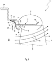
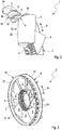
- FIGS. 1 to 5 comprises an axial fan 1, by means of which cooling air for a cooling device, not shown here, of a motor vehicle can be conveyed, a fan wheel 2 and a frame ring 3.
- the fan wheel 2 has a plurality of blades 5 extending from a hub 4 and a shroud 6, which encloses the blades 5 and rotates closed.
- the shroud 6 is supported by the blades 5.
- the shroud 6 is integrally formed on the blades 5.
- the fan wheel 2 rotates about a rotation axis 7, by which a circumferential direction 8 of the fan wheel 2 or of the axial fan 1 is also defined.
- the blades 5 are arranged distributed in the circumferential direction 8 on the hub 4. In this case, the blades 5 may expediently be integrally formed on the hub 4.
- the Zargenring 3 is coaxial with the shroud 6, in such a way that thereby an annular gap 9 is formed between the shroud 6 and the Zargenring 3.
- the axial fan 1 also has at least one inlet nozzle 10.
- the rotation of the fan wheel 2 leads to a semi-axial main flow 11, which in FIG. 5 indicated by arrows.
- a return flow 12 the in Fig. 1 also indicated by an arrow.
- the return flow 12 begins at an exit side 13 of the fan 2 and leads radially outward on the shroud 6 in the direction of the annular gap 9.
- the respective inlet nozzle 10 leads to a deflection of this return flow 12 towards an inlet side 14 of the fan wheel 2.
- the respective inlet nozzle 10 is arranged on the shroud 6.
- the respective inlet nozzle 10 is integrally formed on the shroud 6
- the respective inlet nozzle 10 is located at an inlet end of the shroud 6.
- the shroud 6 according to Fig. 1 have an outwardly projecting circulation 15, which can act as a diffuser and / or improves the formation of the return flow 12.
- annular gap seal 16 is provided, with the aid of which the annular gap 9 is sealed or at least throttled.
- the annular gap seal 16 generates the annular gap seal 16 a strong throttling of the annular gap 9, so that only a relatively small leakage flow 17 can flow through the annular gap 9.
- the annular gap seal 16 is arranged on the shroud 6.
- the annular gap seal 16 is molded onto the shroud 6.
- the annular gap seal 16 is arranged in the region of the respective inlet nozzle 10 on the shroud 6, ie on the inlet side.
- the annular gap seal 16 has a profile in longitudinal section, which has a fixing region 18 fixed on the jacket ring 6 and a freestanding sealing region 19 extending from the fixing region 18.
- the annular gap seal 16 is elastic at least in the sealing region 19. This refers to elasticities that are greater than the elasticities of the shroud 6, the blades 5 and / or the Zargenrings 3.
- the sealing portion 19 is spatially arranged so that it is in operation of the axial fan 1 due to the centrifugal forces 20 occurring in FIG. 1 are indicated by an arrow, is driven and thereby deformed elastically and thereby moves in the direction of Zargenring 3.
- the shroud 6 can have at least one inflow opening 21 for the respective inlet nozzle 10, through which the return flow 12 can pass during the operation of the axial ventilator 1 and can enter the respective inflow nozzle 10.
- the respective inflow opening 21 penetrates the shroud 6 radially.
- the respective inflow opening 21 is arranged upstream of the inlet side 14 with respect to the main flow 11.
- On such inflow openings 21, which pass through the shroud 6 radially, can be dispensed with, for example, when the respective inlet nozzle 10 is fixedly connected via webs with the shroud 6, which are spaced apart in the circumferential direction 8.
- the fan 2 builds axially comparatively large.
- the inflow openings 21 penetrate the shroud 6.
- the at least one inflow opening 21 generates a return flow 12, from which a leakage flow 17 branches off, through which the elastic sealing area 19 is guided without contact on the frame ring 3 during operation of the axial ventilator 1.
- a minimized leakage flow is accepted which, however, forms an air cushion which prevents the sealing area 19 from being looped along the frame ring 3 and thus an increased wear of the sealing area 19.
- annular inlet nozzle 10 ' In order to fluidly connect this annular inlet nozzle 10 'as uniformly as possible with the return flow 12 in the circumferential direction 8, a plurality of inflow openings 21 are provided which are distributed in the circumferential direction 8.
- a plurality of inlet nozzles 10 are provided, which are arranged distributed in the circumferential direction 8 on the shroud 6. These multiple inlet nozzles 10 are referred to below as separate inlet nozzles 10 ".
- the jacket ring 6 has exactly one inlet opening 21 for each separate inlet nozzle 10" FIGS. 4 and 5 1, each blade 5 is assigned exactly one separate inlet nozzle 10 ", whereby the respective separate inlet nozzle 10" is arranged in the region of a leading edge 22 of the associated blade 5.
- the leading edge 22 is positioned centrally to the associated inflow opening 21.
- the inflow openings 21 are configured in each case as elongated holes or as elongated openings, the longitudinal direction of which extends in the circumferential direction 8.
- Fig. 1 can be provided at least one flow guide 23, which is arranged in at least one inlet nozzle 10.
- a plurality of such flow guide elements 23 are arranged distributed in the annular inlet nozzle 10 'in the circumferential direction 8.
- the respective flow guide 23 supports the deflection of the return flow 12 within the inlet nozzle 10 in the direction of the inlet side 14.
- the respective flow guide element 23 may in particular be integrally formed on the shroud 6.
- the Zargenring 3 is preferably arranged on a fan cover 24.
- it may be formed integrally, that is, of the same material, on the fan cover 24.
- the fan cover 24 defines an inflow channel 25, which leads the cooling air to the fan 2.
- the Zargenring 3 of the fan cover 24 is free-standing, so he spatially only on the fan cover 24 is positioned.
- the fan cover 24 can connect directly to a heat exchanger, not shown here. This heat exchanger is a component of the aforementioned cooling device of the vehicle and, for example, flows through an air flow generated and / or assisted by means of the axial fan 1.
- said heat exchanger is arranged upstream of the fan wheel 2, so that the fan wheel 2 sucks in the air flow through the heat exchanger.
- the fan cover 24 surrounds the Zargenring 3 and the shroud 6 coaxially and leads to a downstream of the fan 2 arranged heat exchanger.
- the shroud 6 can be cylindrically shaped between its inlet-side end and its exit-side end.
- the Zargenring 3 may be cylindrically shaped.
Landscapes
- Engineering & Computer Science (AREA)
- Mechanical Engineering (AREA)
- General Engineering & Computer Science (AREA)
- Structures Of Non-Positive Displacement Pumps (AREA)
Claims (13)
- Ventilateur axial servant à refouler de l'air de refroidissement pour un dispositif de refroidissement d'un véhicule automobile,- avec une roue de ventilateur (2), qui présente plusieurs aubes (5) partant d'un moyeu (4) et une frette (6) encadrant les aubes (5), fermée en périphérie, supportée par les aubes (5),- avec un anneau de châssis (3), qui est disposé de manière coaxiale par rapport à la frette (6) de telle sorte qu'une fente annulaire (9) se forme entre la frette (6) et l'anneau de châssis (3),- dans lequel au moins une buse d'admission (10) est réalisée dans la zone de la fente annulaire (9), laquelle buse d'admission renvoie un écoulement de reflux (12) se formant lors du fonctionnement du ventilateur axial (1) dans la zone de la frette (6) en direction d'un côté d'entrée (14) de la roue de ventilateur (2),caractérisé en ce- que l'au moins une buse d'admission (10) est disposée au niveau de la frette (6), dans lequel la frette (6) contient pour la buse d'admission (10) respective au moins une ouverture de flux entrant (21), qui traverse de manière radiale en amont du côté d'entrée (14) la frette (6) par rapport à un écoulement principal (11) refoulé par la roue de ventilateur (2) lors du fonctionnement du ventilateur axial (1).
- Ventilateur axial selon la revendication 1,
caractérisé en ce
que la frette (6) présente pour ladite buse d'admission (10, 10') plusieurs ouvertures de flux entrant (21) de ce type disposées de manière répartie dans la direction périphérique (8). - Ventilateur axial selon la revendication 1 ou 2,
caractérisé en ce
que l'au moins une ouverture de flux entrant (21) génère un écoulement de reflux (12), duquel est dévié un écoulement de fuite (17), par lequel, lors du fonctionnement du ventilateur axial (1), la zone étanche (19) élastique est guidée sans contact au niveau de l'anneau de châssis (3). - Ventilateur axial selon l'une des revendications 1 à 3,
caractérisé en ce
qu'une telle buse d'admission (10, 10') unique est prévue, laquelle s'étend de manière fermée en présentant une forme annulaire dans la direction périphérique (8). - Ventilateur axial selon l'une des revendications 1 à 3,
caractérisé en ce
que plusieurs buses d'admission (10, 10") de ce type sont prévues, lesquelles sont disposées de manière répartie dans la direction périphérique (8). - Ventilateur axial selon l'une des revendications 1 à 3,
caractérisé en ce- que plusieurs buses d'admission (10, 10") de ce type sont prévues, lesquelles sont disposées de manière répartie dans la direction périphérique (8),- que la frette (6) présente pour chaque buse d'admission (10, 10") au moins une ouverture de flux entrant (21) de ce type. - Ventilateur axial selon la revendication 5 ou 6,
caractérisé en ce
que précisément une buse d'admission (10, 10") de ce type est associée à chaque aube (5). - Ventilateur axial selon la revendication 7,
caractérisé en ce
que la buse d'admission (10, 10") respective est disposée dans la zone d'une arête de flux entrant (22) de l'aube (5) associée. - Ventilateur axial selon l'une des revendications 1 à 8,
caractérisé par au moins un élément de guidage d'écoulement (23), qui est disposé dans l'au moins une buse d'admission (10). - Ventilateur axial selon l'une des revendications précédentes,
caractérisé en ce
qu'un joint d'étanchéité de fente annulaire (16) disposé au niveau de la frette (6) est prévu afin d'étanchéifier et/ou d'étrangler la fente annulaire (9). - Ventilateur axial selon la revendication 10,
caractérisé en ce
que le joint d'étanchéité de fente annulaire (16) est constitué d'un matériau autre que celui de la frette (6). - Ventilateur axial selon la revendication 10 ou 11,
caractérisé en ce
que le joint d'étanchéité de fente annulaire (16) est, par rapport à la frette (6), un composant séparé, qui est installé au niveau de la frette (6), par exemple qui y est appliqué par injection, par collage, par soudage, par vulcanisation, par vissage, par rivetage ou par serrage. - Ventilateur axial selon l'une des revendications 10 à 12,
caractérisé en ce
que le joint d'étanchéité de fente annulaire (16) présente dans le profil une zone de fixation (18) fixée au niveau de la frette (6) et une zone étanche (19) élastique dégagée, qui est disposée de telle sorte que lors du fonctionnement du ventilateur axial (1), elle est entraînée par des forces centrifuges, elle se déforme élastiquement et se déplace en direction de l'anneau de châssis (3).
Applications Claiming Priority (1)
| Application Number | Priority Date | Filing Date | Title |
|---|---|---|---|
| DE102013227025.9A DE102013227025A1 (de) | 2013-12-20 | 2013-12-20 | Axiallüfter |
Publications (2)
| Publication Number | Publication Date |
|---|---|
| EP2886873A1 EP2886873A1 (fr) | 2015-06-24 |
| EP2886873B1 true EP2886873B1 (fr) | 2017-05-24 |
Family
ID=52016393
Family Applications (1)
| Application Number | Title | Priority Date | Filing Date |
|---|---|---|---|
| EP14194113.8A Not-in-force EP2886873B1 (fr) | 2013-12-20 | 2014-11-20 | Ventilateur axial |
Country Status (2)
| Country | Link |
|---|---|
| EP (1) | EP2886873B1 (fr) |
| DE (1) | DE102013227025A1 (fr) |
Cited By (3)
| Publication number | Priority date | Publication date | Assignee | Title |
|---|---|---|---|---|
| KR20180133791A (ko) * | 2017-06-07 | 2018-12-17 | 한온시스템 주식회사 | 송풍기 휠과 송풍기 휠을 구비한 난방, 환기 및/또는 공조 시스템 |
| USD860427S1 (en) | 2017-09-18 | 2019-09-17 | Horton, Inc. | Ring fan |
| DE102019202116A1 (de) * | 2019-02-18 | 2020-08-20 | Brose Fahrzeugteile SE & Co. Kommanditgesellschaft, Würzburg | Kühlerlüfter eines Kraftfahrzeugs |
Families Citing this family (3)
| Publication number | Priority date | Publication date | Assignee | Title |
|---|---|---|---|---|
| DE102015214356A1 (de) | 2015-07-29 | 2017-02-02 | Brose Fahrzeugteile GmbH & Co. Kommanditgesellschaft, Würzburg | Lüfterrad und Kühlerlüftermodul |
| WO2020028010A1 (fr) | 2018-08-02 | 2020-02-06 | Horton, Inc. | Ventilateur de refroidissement de véhicule à faible plénitude |
| CN115059641B (zh) * | 2022-07-18 | 2026-01-02 | 合肥速帆汽车科技有限公司 | 一种轴流扇叶结构及轴流风机 |
Family Cites Families (13)
| Publication number | Priority date | Publication date | Assignee | Title |
|---|---|---|---|---|
| DE3304297A1 (de) | 1982-03-15 | 1984-03-15 | Süddeutsche Kühlerfabrik Julius Fr. Behr GmbH & Co KG, 7000 Stuttgart | Axialgeblaese, insbesondere fuer kuehler einer wassergekuehlten brennkraftmaschine |
| DE3538671A1 (de) | 1985-10-31 | 1987-05-07 | Kloeckner Humboldt Deutz Ag | Profildichtung |
| JPH09505375A (ja) | 1993-08-30 | 1997-05-27 | エアフロー リサーチ マニュファクチュアリング コーポレーション | 帯付き軸流ファンと共に使用するための再循環制御を伴うハウジング |
| DE19803502B4 (de) * | 1998-01-30 | 2006-01-05 | Behr Gmbh & Co. Kg | Lüfteranordnung |
| JP4592907B2 (ja) * | 2000-09-28 | 2010-12-08 | 株式会社ティラド | ファンのシール構造 |
| DE502004011172D1 (de) * | 2003-07-15 | 2010-07-01 | Ebm Papst St Georgen Gmbh & Co | Lüfteranordnung, und Verfahren zur Herstellung einer solchen |
| FR2879683B1 (fr) * | 2004-12-17 | 2010-09-17 | Valeo Systemes Dessuyage | Ventilateur comportant une nervure externe positionnee axialement par rapport a la jupe annulaire peripherique |
| DE102006047236B4 (de) | 2006-10-04 | 2017-06-29 | Mahle International Gmbh | Axiallüfter eingerichtet zur Förderung von Kühlluft einer Kühlvorrichtung eines Kraftfahrzeuges |
| DE102006049076B4 (de) | 2006-10-13 | 2019-09-26 | Mahle International Gmbh | Axiallüfter eingerichtet zur Förderung von Kühlluft für eine Kühlvorrichtung eines Kraftfahrzeuges |
| DE112007003353A5 (de) * | 2006-12-18 | 2009-12-03 | Temic Automotive Electric Motors Gmbh | Axiallüfter für einen Fahrzeugkühler |
| US8475111B2 (en) | 2007-04-05 | 2013-07-02 | Borgwarner Inc. | Ring fan and shroud air guide system |
| DE102010039219A1 (de) * | 2010-08-11 | 2012-02-16 | Behr Gmbh & Co. Kg | Lüfter, insbesondere für ein Motorkühlungsgebläse in einem Kraftfahrzeug |
| DE102012207552A1 (de) | 2011-05-13 | 2012-11-15 | Brose Fahrzeugteile GmbH & Co. Kommanditgesellschaft, Würzburg | Kühlerlüftermodul |
-
2013
- 2013-12-20 DE DE102013227025.9A patent/DE102013227025A1/de not_active Withdrawn
-
2014
- 2014-11-20 EP EP14194113.8A patent/EP2886873B1/fr not_active Not-in-force
Non-Patent Citations (1)
| Title |
|---|
| None * |
Cited By (4)
| Publication number | Priority date | Publication date | Assignee | Title |
|---|---|---|---|---|
| KR20180133791A (ko) * | 2017-06-07 | 2018-12-17 | 한온시스템 주식회사 | 송풍기 휠과 송풍기 휠을 구비한 난방, 환기 및/또는 공조 시스템 |
| USD860427S1 (en) | 2017-09-18 | 2019-09-17 | Horton, Inc. | Ring fan |
| DE102019202116A1 (de) * | 2019-02-18 | 2020-08-20 | Brose Fahrzeugteile SE & Co. Kommanditgesellschaft, Würzburg | Kühlerlüfter eines Kraftfahrzeugs |
| WO2020169546A1 (fr) | 2019-02-18 | 2020-08-27 | Brose Fahrzeugteile SE & Co. Kommanditgesellschaft, Würzburg | Ventilateur de radiateur d'un véhicule à moteur |
Also Published As
| Publication number | Publication date |
|---|---|
| DE102013227025A1 (de) | 2015-06-25 |
| EP2886873A1 (fr) | 2015-06-24 |
Similar Documents
| Publication | Publication Date | Title |
|---|---|---|
| EP2886873B1 (fr) | Ventilateur axial | |
| EP2236837B1 (fr) | Ventilateur axial, en particulier pour un véhicule automobile | |
| DE2657840A1 (de) | Geraeuscharme kuehlanlage fuer brennkraftmaschinen | |
| EP2179143B1 (fr) | Refroidissement de fente entre une paroi de chambre de combustion et une paroi de turbine d'une installation de turbine à gaz | |
| DE112014005032T5 (de) | Kompressor-Luftrückführung mit verringerter Geräuschbildung | |
| DE102012216288A1 (de) | Zentrifugalgebläseanordnung | |
| EP1736635B1 (fr) | Système de transfert d'air entre le compresseur et la turbine d'une turbine à gaz | |
| DE112016002636T5 (de) | Elektrische Maschine für ein Fahrzeug | |
| WO2008092427A1 (fr) | Turbine à gaz présentant une couronne directrice et un mélangeur | |
| EP2557315A2 (fr) | Palier à roulement et pompe à vide dotée d'un palier à roulement | |
| EP3405679A1 (fr) | Ventilateur diagonal | |
| EP2435210B1 (fr) | Machine-outil, notamment machine-outil à main | |
| EP3124742B1 (fr) | Turbine a gaz | |
| EP2112332B1 (fr) | Anneau support de distributeur avec canal pressurisé | |
| EP1887195B1 (fr) | Dispositif de refroidissement pour un véhicule automobile | |
| DE202016106538U1 (de) | Diagonalventilator | |
| DE102015216335A1 (de) | Lüfter für eine Kühleranordnung | |
| EP2314882B1 (fr) | Elément de guidage d'air pour un ventilateur axial | |
| DE102015012225A1 (de) | Leiteinrichtung für einen Verdichter eines Abgasturboladers | |
| EP2478226B1 (fr) | Ventilateur pour un moteur à combustion interne | |
| EP3029329B1 (fr) | Ventilateurs lateraux, en particulier pour un appareil de chauffage de vehicule | |
| DE102014224657A1 (de) | Klimatisierungsanlage mit Radialgebläse | |
| EP2513483B1 (fr) | Pompe à carburant | |
| EP2020489A1 (fr) | Dispositif destiné au refroidissement d'un moteur | |
| DE102014204043A1 (de) | Lüfterrad eines Axiallüfters |
Legal Events
| Date | Code | Title | Description |
|---|---|---|---|
| PUAI | Public reference made under article 153(3) epc to a published international application that has entered the european phase |
Free format text: ORIGINAL CODE: 0009012 |
|
| 17P | Request for examination filed |
Effective date: 20141120 |
|
| AK | Designated contracting states |
Kind code of ref document: A1 Designated state(s): AL AT BE BG CH CY CZ DE DK EE ES FI FR GB GR HR HU IE IS IT LI LT LU LV MC MK MT NL NO PL PT RO RS SE SI SK SM TR |
|
| AX | Request for extension of the european patent |
Extension state: BA ME |
|
| R17P | Request for examination filed (corrected) |
Effective date: 20151214 |
|
| RBV | Designated contracting states (corrected) |
Designated state(s): AL AT BE BG CH CY CZ DE DK EE ES FI FR GB GR HR HU IE IS IT LI LT LU LV MC MK MT NL NO PL PT RO RS SE SI SK SM TR |
|
| 17Q | First examination report despatched |
Effective date: 20160609 |
|
| GRAP | Despatch of communication of intention to grant a patent |
Free format text: ORIGINAL CODE: EPIDOSNIGR1 |
|
| INTG | Intention to grant announced |
Effective date: 20170214 |
|
| GRAS | Grant fee paid |
Free format text: ORIGINAL CODE: EPIDOSNIGR3 |
|
| GRAA | (expected) grant |
Free format text: ORIGINAL CODE: 0009210 |
|
| AK | Designated contracting states |
Kind code of ref document: B1 Designated state(s): AL AT BE BG CH CY CZ DE DK EE ES FI FR GB GR HR HU IE IS IT LI LT LU LV MC MK MT NL NO PL PT RO RS SE SI SK SM TR |
|
| REG | Reference to a national code |
Ref country code: GB Ref legal event code: FG4D Free format text: NOT ENGLISH |
|
| REG | Reference to a national code |
Ref country code: CH Ref legal event code: EP |
|
| REG | Reference to a national code |
Ref country code: IE Ref legal event code: FG4D Free format text: LANGUAGE OF EP DOCUMENT: GERMAN |
|
| REG | Reference to a national code |
Ref country code: AT Ref legal event code: REF Ref document number: 896158 Country of ref document: AT Kind code of ref document: T Effective date: 20170615 |
|
| REG | Reference to a national code |
Ref country code: DE Ref legal event code: R096 Ref document number: 502014003933 Country of ref document: DE |
|
| REG | Reference to a national code |
Ref country code: NL Ref legal event code: MP Effective date: 20170524 |
|
| REG | Reference to a national code |
Ref country code: LT Ref legal event code: MG4D |
|
| PG25 | Lapsed in a contracting state [announced via postgrant information from national office to epo] |
Ref country code: HR Free format text: LAPSE BECAUSE OF FAILURE TO SUBMIT A TRANSLATION OF THE DESCRIPTION OR TO PAY THE FEE WITHIN THE PRESCRIBED TIME-LIMIT Effective date: 20170524 Ref country code: ES Free format text: LAPSE BECAUSE OF FAILURE TO SUBMIT A TRANSLATION OF THE DESCRIPTION OR TO PAY THE FEE WITHIN THE PRESCRIBED TIME-LIMIT Effective date: 20170524 Ref country code: GR Free format text: LAPSE BECAUSE OF FAILURE TO SUBMIT A TRANSLATION OF THE DESCRIPTION OR TO PAY THE FEE WITHIN THE PRESCRIBED TIME-LIMIT Effective date: 20170825 Ref country code: FI Free format text: LAPSE BECAUSE OF FAILURE TO SUBMIT A TRANSLATION OF THE DESCRIPTION OR TO PAY THE FEE WITHIN THE PRESCRIBED TIME-LIMIT Effective date: 20170524 Ref country code: NO Free format text: LAPSE BECAUSE OF FAILURE TO SUBMIT A TRANSLATION OF THE DESCRIPTION OR TO PAY THE FEE WITHIN THE PRESCRIBED TIME-LIMIT Effective date: 20170824 Ref country code: LT Free format text: LAPSE BECAUSE OF FAILURE TO SUBMIT A TRANSLATION OF THE DESCRIPTION OR TO PAY THE FEE WITHIN THE PRESCRIBED TIME-LIMIT Effective date: 20170524 |
|
| REG | Reference to a national code |
Ref country code: FR Ref legal event code: PLFP Year of fee payment: 4 |
|
| PG25 | Lapsed in a contracting state [announced via postgrant information from national office to epo] |
Ref country code: NL Free format text: LAPSE BECAUSE OF FAILURE TO SUBMIT A TRANSLATION OF THE DESCRIPTION OR TO PAY THE FEE WITHIN THE PRESCRIBED TIME-LIMIT Effective date: 20170524 Ref country code: IS Free format text: LAPSE BECAUSE OF FAILURE TO SUBMIT A TRANSLATION OF THE DESCRIPTION OR TO PAY THE FEE WITHIN THE PRESCRIBED TIME-LIMIT Effective date: 20170924 Ref country code: LV Free format text: LAPSE BECAUSE OF FAILURE TO SUBMIT A TRANSLATION OF THE DESCRIPTION OR TO PAY THE FEE WITHIN THE PRESCRIBED TIME-LIMIT Effective date: 20170524 Ref country code: BG Free format text: LAPSE BECAUSE OF FAILURE TO SUBMIT A TRANSLATION OF THE DESCRIPTION OR TO PAY THE FEE WITHIN THE PRESCRIBED TIME-LIMIT Effective date: 20170824 Ref country code: SE Free format text: LAPSE BECAUSE OF FAILURE TO SUBMIT A TRANSLATION OF THE DESCRIPTION OR TO PAY THE FEE WITHIN THE PRESCRIBED TIME-LIMIT Effective date: 20170524 Ref country code: RS Free format text: LAPSE BECAUSE OF FAILURE TO SUBMIT A TRANSLATION OF THE DESCRIPTION OR TO PAY THE FEE WITHIN THE PRESCRIBED TIME-LIMIT Effective date: 20170524 |
|
| PG25 | Lapsed in a contracting state [announced via postgrant information from national office to epo] |
Ref country code: RO Free format text: LAPSE BECAUSE OF FAILURE TO SUBMIT A TRANSLATION OF THE DESCRIPTION OR TO PAY THE FEE WITHIN THE PRESCRIBED TIME-LIMIT Effective date: 20170524 Ref country code: CZ Free format text: LAPSE BECAUSE OF FAILURE TO SUBMIT A TRANSLATION OF THE DESCRIPTION OR TO PAY THE FEE WITHIN THE PRESCRIBED TIME-LIMIT Effective date: 20170524 Ref country code: DK Free format text: LAPSE BECAUSE OF FAILURE TO SUBMIT A TRANSLATION OF THE DESCRIPTION OR TO PAY THE FEE WITHIN THE PRESCRIBED TIME-LIMIT Effective date: 20170524 Ref country code: EE Free format text: LAPSE BECAUSE OF FAILURE TO SUBMIT A TRANSLATION OF THE DESCRIPTION OR TO PAY THE FEE WITHIN THE PRESCRIBED TIME-LIMIT Effective date: 20170524 Ref country code: SK Free format text: LAPSE BECAUSE OF FAILURE TO SUBMIT A TRANSLATION OF THE DESCRIPTION OR TO PAY THE FEE WITHIN THE PRESCRIBED TIME-LIMIT Effective date: 20170524 |
|
| REG | Reference to a national code |
Ref country code: DE Ref legal event code: R097 Ref document number: 502014003933 Country of ref document: DE |
|
| PG25 | Lapsed in a contracting state [announced via postgrant information from national office to epo] |
Ref country code: PL Free format text: LAPSE BECAUSE OF FAILURE TO SUBMIT A TRANSLATION OF THE DESCRIPTION OR TO PAY THE FEE WITHIN THE PRESCRIBED TIME-LIMIT Effective date: 20170524 Ref country code: SM Free format text: LAPSE BECAUSE OF FAILURE TO SUBMIT A TRANSLATION OF THE DESCRIPTION OR TO PAY THE FEE WITHIN THE PRESCRIBED TIME-LIMIT Effective date: 20170524 Ref country code: IT Free format text: LAPSE BECAUSE OF FAILURE TO SUBMIT A TRANSLATION OF THE DESCRIPTION OR TO PAY THE FEE WITHIN THE PRESCRIBED TIME-LIMIT Effective date: 20170524 |
|
| PLBE | No opposition filed within time limit |
Free format text: ORIGINAL CODE: 0009261 |
|
| STAA | Information on the status of an ep patent application or granted ep patent |
Free format text: STATUS: NO OPPOSITION FILED WITHIN TIME LIMIT |
|
| 26N | No opposition filed |
Effective date: 20180227 |
|
| PG25 | Lapsed in a contracting state [announced via postgrant information from national office to epo] |
Ref country code: SI Free format text: LAPSE BECAUSE OF FAILURE TO SUBMIT A TRANSLATION OF THE DESCRIPTION OR TO PAY THE FEE WITHIN THE PRESCRIBED TIME-LIMIT Effective date: 20170524 |
|
| PG25 | Lapsed in a contracting state [announced via postgrant information from national office to epo] |
Ref country code: MC Free format text: LAPSE BECAUSE OF FAILURE TO SUBMIT A TRANSLATION OF THE DESCRIPTION OR TO PAY THE FEE WITHIN THE PRESCRIBED TIME-LIMIT Effective date: 20170524 |
|
| PG25 | Lapsed in a contracting state [announced via postgrant information from national office to epo] |
Ref country code: CH Free format text: LAPSE BECAUSE OF NON-PAYMENT OF DUE FEES Effective date: 20171130 Ref country code: LI Free format text: LAPSE BECAUSE OF NON-PAYMENT OF DUE FEES Effective date: 20171130 |
|
| PG25 | Lapsed in a contracting state [announced via postgrant information from national office to epo] |
Ref country code: LU Free format text: LAPSE BECAUSE OF NON-PAYMENT OF DUE FEES Effective date: 20171120 |
|
| REG | Reference to a national code |
Ref country code: BE Ref legal event code: MM Effective date: 20171130 |
|
| REG | Reference to a national code |
Ref country code: IE Ref legal event code: MM4A |
|
| PG25 | Lapsed in a contracting state [announced via postgrant information from national office to epo] |
Ref country code: MT Free format text: LAPSE BECAUSE OF FAILURE TO SUBMIT A TRANSLATION OF THE DESCRIPTION OR TO PAY THE FEE WITHIN THE PRESCRIBED TIME-LIMIT Effective date: 20170524 |
|
| PG25 | Lapsed in a contracting state [announced via postgrant information from national office to epo] |
Ref country code: IE Free format text: LAPSE BECAUSE OF NON-PAYMENT OF DUE FEES Effective date: 20171120 |
|
| PG25 | Lapsed in a contracting state [announced via postgrant information from national office to epo] |
Ref country code: BE Free format text: LAPSE BECAUSE OF NON-PAYMENT OF DUE FEES Effective date: 20171130 |
|
| PGFP | Annual fee paid to national office [announced via postgrant information from national office to epo] |
Ref country code: DE Payment date: 20190131 Year of fee payment: 5 |
|
| PG25 | Lapsed in a contracting state [announced via postgrant information from national office to epo] |
Ref country code: HU Free format text: LAPSE BECAUSE OF FAILURE TO SUBMIT A TRANSLATION OF THE DESCRIPTION OR TO PAY THE FEE WITHIN THE PRESCRIBED TIME-LIMIT; INVALID AB INITIO Effective date: 20141120 |
|
| GBPC | Gb: european patent ceased through non-payment of renewal fee |
Effective date: 20181120 |
|
| PG25 | Lapsed in a contracting state [announced via postgrant information from national office to epo] |
Ref country code: CY Free format text: LAPSE BECAUSE OF FAILURE TO SUBMIT A TRANSLATION OF THE DESCRIPTION OR TO PAY THE FEE WITHIN THE PRESCRIBED TIME-LIMIT Effective date: 20170524 |
|
| PG25 | Lapsed in a contracting state [announced via postgrant information from national office to epo] |
Ref country code: MK Free format text: LAPSE BECAUSE OF FAILURE TO SUBMIT A TRANSLATION OF THE DESCRIPTION OR TO PAY THE FEE WITHIN THE PRESCRIBED TIME-LIMIT Effective date: 20170524 |
|
| PG25 | Lapsed in a contracting state [announced via postgrant information from national office to epo] |
Ref country code: GB Free format text: LAPSE BECAUSE OF NON-PAYMENT OF DUE FEES Effective date: 20181120 |
|
| PGFP | Annual fee paid to national office [announced via postgrant information from national office to epo] |
Ref country code: FR Payment date: 20191127 Year of fee payment: 6 |
|
| PG25 | Lapsed in a contracting state [announced via postgrant information from national office to epo] |
Ref country code: TR Free format text: LAPSE BECAUSE OF FAILURE TO SUBMIT A TRANSLATION OF THE DESCRIPTION OR TO PAY THE FEE WITHIN THE PRESCRIBED TIME-LIMIT Effective date: 20170524 |
|
| PG25 | Lapsed in a contracting state [announced via postgrant information from national office to epo] |
Ref country code: PT Free format text: LAPSE BECAUSE OF FAILURE TO SUBMIT A TRANSLATION OF THE DESCRIPTION OR TO PAY THE FEE WITHIN THE PRESCRIBED TIME-LIMIT Effective date: 20170524 |
|
| REG | Reference to a national code |
Ref country code: DE Ref legal event code: R119 Ref document number: 502014003933 Country of ref document: DE |
|
| PG25 | Lapsed in a contracting state [announced via postgrant information from national office to epo] |
Ref country code: AL Free format text: LAPSE BECAUSE OF FAILURE TO SUBMIT A TRANSLATION OF THE DESCRIPTION OR TO PAY THE FEE WITHIN THE PRESCRIBED TIME-LIMIT Effective date: 20170524 |
|
| PG25 | Lapsed in a contracting state [announced via postgrant information from national office to epo] |
Ref country code: DE Free format text: LAPSE BECAUSE OF NON-PAYMENT OF DUE FEES Effective date: 20200603 |
|
| REG | Reference to a national code |
Ref country code: AT Ref legal event code: MM01 Ref document number: 896158 Country of ref document: AT Kind code of ref document: T Effective date: 20191120 |
|
| PG25 | Lapsed in a contracting state [announced via postgrant information from national office to epo] |
Ref country code: AT Free format text: LAPSE BECAUSE OF NON-PAYMENT OF DUE FEES Effective date: 20191120 |
|
| PG25 | Lapsed in a contracting state [announced via postgrant information from national office to epo] |
Ref country code: FR Free format text: LAPSE BECAUSE OF NON-PAYMENT OF DUE FEES Effective date: 20201130 |