EP2314882B1 - Elément de guidage d'air pour un ventilateur axial - Google Patents
Elément de guidage d'air pour un ventilateur axial Download PDFInfo
- Publication number
- EP2314882B1 EP2314882B1 EP10187222A EP10187222A EP2314882B1 EP 2314882 B1 EP2314882 B1 EP 2314882B1 EP 10187222 A EP10187222 A EP 10187222A EP 10187222 A EP10187222 A EP 10187222A EP 2314882 B1 EP2314882 B1 EP 2314882B1
- Authority
- EP
- European Patent Office
- Prior art keywords
- air guide
- guide vanes
- guiding element
- element according
- air guiding
- Prior art date
- Legal status (The legal status is an assumption and is not a legal conclusion. Google has not performed a legal analysis and makes no representation as to the accuracy of the status listed.)
- Active
Links
Images

Classifications
-
- F—MECHANICAL ENGINEERING; LIGHTING; HEATING; WEAPONS; BLASTING
- F04—POSITIVE - DISPLACEMENT MACHINES FOR LIQUIDS; PUMPS FOR LIQUIDS OR ELASTIC FLUIDS
- F04D—NON-POSITIVE-DISPLACEMENT PUMPS
- F04D29/00—Details, component parts, or accessories
- F04D29/70—Suction grids; Strainers; Dust separation; Cleaning
- F04D29/701—Suction grids; Strainers; Dust separation; Cleaning especially adapted for elastic fluid pumps
- F04D29/703—Suction grids; Strainers; Dust separation; Cleaning especially adapted for elastic fluid pumps specially for fans, e.g. fan guards
-
- F—MECHANICAL ENGINEERING; LIGHTING; HEATING; WEAPONS; BLASTING
- F04—POSITIVE - DISPLACEMENT MACHINES FOR LIQUIDS; PUMPS FOR LIQUIDS OR ELASTIC FLUIDS
- F04D—NON-POSITIVE-DISPLACEMENT PUMPS
- F04D29/00—Details, component parts, or accessories
- F04D29/40—Casings; Connections of working fluid
- F04D29/52—Casings; Connections of working fluid for axial pumps
- F04D29/522—Casings; Connections of working fluid for axial pumps especially adapted for elastic fluid pumps
- F04D29/526—Details of the casing section radially opposing blade tips
-
- F—MECHANICAL ENGINEERING; LIGHTING; HEATING; WEAPONS; BLASTING
- F04—POSITIVE - DISPLACEMENT MACHINES FOR LIQUIDS; PUMPS FOR LIQUIDS OR ELASTIC FLUIDS
- F04D—NON-POSITIVE-DISPLACEMENT PUMPS
- F04D29/00—Details, component parts, or accessories
- F04D29/40—Casings; Connections of working fluid
- F04D29/52—Casings; Connections of working fluid for axial pumps
- F04D29/54—Fluid-guiding means, e.g. diffusers
- F04D29/541—Specially adapted for elastic fluid pumps
- F04D29/542—Bladed diffusers
- F04D29/544—Blade shapes
Definitions
- the present invention relates to an air guide element for an axial fan, consisting of a one-piece molded part with a plurality of circumferentially distributed around a longitudinal axis and substantially radially disposed wing-like air guide vanes and with an integrally connected to the air guide vanes, wherein the air guide vanes seen in the circumferential direction extend obliquely to the axial direction in each case between an inflow-side blade edge facing the fan and an opposite outflow-side blade edge, and wherein the protective grille consists of concentric and circumferentially extending grid webs connected to the air guide vanes.
- Such air guide elements are arranged with their air guide vanes immediately behind an axial fan to redirect the offset from the axial fan impeller air in a possible axial and uniform flow.
- Such an air guide is therefore often called "Nachleitrad” or "flow rectifier”.
- EP 1 895 166 B1 discloses all the features of the preamble of claim 1, such a "flow straightener", wherein the air guide vanes are internally connected to a substantially annular retaining sleeve for supporting a fan drive motor and the outside with a conically narrowing nozzle ring.
- a protective grid on the downstream side is integrally connected to the downstream edges of the air guide vanes. This entire unit should be designed as an integral molded part, in particular made of plastic.
- the present invention is based on the object to improve an air guide element of the generic type described above so that it can be produced with streamlined properties in a particularly simple and economical manner.
- the invention provides that the grid webs of the protective grid consist of web sections, which are each connected at one end to the upstream (front) blade edges of the air vanes and the other end with the respective downstream downstream (rear) blade edges of each adjacent circumferentially air vanes.
- the particular, inventive course of the grid webs or the web portions of the protective grid advantageously does not affect the streamlined properties of the air guide element.
- the air guide vanes each have a wing-like design with a contour that is curved in the circumferential direction in such a way that they have a greater oblique inclination in the region of the upstream blade edges than in the region of the downstream blade edges, a favorable flow guidance and flow guidance is achieved.
- the peripheral component of the outflow velocity of Fan flow in the axial direction deflected almost lossless, so that speed energy is converted back into static pressure.
- the air vanes are connected in one piece with their radially outer ends with a substantially hollow cylindrical outer ring and with their inner ends with a coaxial, in particular also substantially hollow cylindrical inner ring.
- the air guide can be connected to a fan unit or with a drive motor.
- the fan unit has an axial fan wheel, which is to be arranged immediately in front of the inflow side of the air guide vanes.
- the outer ring also forms a receiving space for the fan wheel.
- the outer ring is used for external attachment of the entire unit in a ventilation unit or a ventilation system.
- the air guide vanes integrally connecting the outer ring to the inner ring can also be designed at least proportionally with a mechanical bearing function in order to transmit forces and torques of the fan motor to the outer ring. But it can also be provided with a mechanical support function additional, arranged radially between the outer ring and the inner ring holding struts.
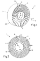
- An inventive air guide 1 consists of a one-piece molding 2 in particular made of plastic (injection molded part).
- the air guide element 1 has a plurality of air guide vanes 4, which are distributed in the circumferential direction about a longitudinal axis 6 around and are arranged substantially radially.
- the longitudinal axis 6 corresponds essentially to the desired flow direction of a medium flowing through the air guide element 1, in particular air, wherein the longitudinal axis 6 in Fig. 2 perpendicular to the plane of the drawing.
- the air guiding element 1 furthermore has a protective grille 8, which is integrally connected to the air guide vanes 4.
- the spoiler 1 is immediately downstream of an axial fan, not shown, and it also serves as protection against contact by the protective grid 8.
- the air guide vanes 4 each extend obliquely to the axial direction between an inflow-side blade edge 10 facing the fan and an opposite, outflow-side blade edge 12.
- the air guide vanes 4 can each have a wing-like design with a contour that is curved in the circumferential direction in such a way that they have a greater oblique inclination in the region of the inflow-side blade edges 10 than in the region of the downstream blade edges 12. This is in particular on Fig. 3 directed. It is clear that the air coming from the fan wheel on the inflow side in the direction of the arrow 14 is deflected over the air guide vanes 4 in the axial direction according to the arrows 16.
- the guard 8 is according to Fig. 1 and 2 from concentric and in particular annular in the circumferential direction, integrally connected to the air guide vanes 4 grid webs 18th
- the grid webs 18 consist of web sections 18a, wherein each web section 18a is connected at one end to the leading edge 10 of one of the air guide vanes 4 and the other downstream end edge 12 of the circumferentially adjacent air guide 4. According to 3 and 4 Thus, the web portions 18a and the air vanes 4 extend in the circumferential direction zigzag axially back and forth.
- the one-piece mold part 2 in a two-part mold only and can be removed from the mold due to a non-undercut design and slide-free.
- the air guide vanes 4 are connected in one piece with their radially outer ends with an outer ring 20 and with their inner ends with a coaxial inner ring 22.
- Both rings 20, 22 are preferably formed substantially hollow cylindrical.
- the grid webs 18 and their web portions 18a have been seen in axial plan view (see Fig. 2 ) An arcuate course, wherein the grid bars 18 extend a total of coaxial annular. It is also a spiral course possible.
- the outer ring 20 with the inner ring 22 integrally connecting spoiler blades 4 may be at least partially designed for a mechanical support function.
- radially not shown holding struts may be provided with mechanical support function between the outer ring 20 and the inner ring 22.
- the inner ring 22 In the region of the inner ring 22 means not shown are provided for connection to a fan or a drive motor, also not shown. Furthermore, 20 means for external attachment of the entire unit in a ventilation unit or a ventilation system are provided in the region of the outer ring (also not shown).
- the outer ring 20 encloses on the upstream side of the air guide vanes 4 a receiving space for a fan wheel. This means that the fan wheel to be arranged directly in front of the inflow-side blade edges 10 is still enclosed by the outer ring 20 at least in certain areas.
Landscapes
- Engineering & Computer Science (AREA)
- Mechanical Engineering (AREA)
- General Engineering & Computer Science (AREA)
- Physics & Mathematics (AREA)
- Geometry (AREA)
- Structures Of Non-Positive Displacement Pumps (AREA)
- Laying Of Electric Cables Or Lines Outside (AREA)
Claims (9)
- Élément de guidage de l'air (1) pour un ventilateur axial, formé par un élément profilé (2) moulé d'un seul tenant avec une pluralité de pales de guidage de l'air (4), réparties dans la direction circonférentielle autour d'un axe longitudinal (6) et agencées sensiblement radialement, et avec une grille de protection (8) reliée intégralement aux pales de guidage de l'air (4), dans lequel lesdites pales (4), vues dans la direction circonférentielle, s'étendent respectivement entre un bord amont (10) et un bord aval (12) en étant inclinées par rapport à la direction axiale, et ladite grille de protection (8) est formée par des barreaux (18) reliés aux pales de guidage de l'air (4) et s'étendant sensiblement concentriquement et dans la direction circonférentielle, caractérisé en ce que les barreaux (18) de la grille de protection (8) sont formés par des tronçons (18a) qui sont reliés respectivement par une extrémité avec les bords amont (10) des pales de guidage de l'air (4) et par l'autre extrémité avec les bords aval (12) des pales de guidage de l'air (4) respectivement adjacentes dans la direction circonférentielle.
- Élément de guidage de l'air selon la revendication 1,
caractérisé en ce que les pales de guidage de l'air (4) sont reliées d'un seul tenant par leurs extrémités radialement extérieures à une bague extérieure (20) et par leurs extrémités intérieures à une bague intérieure (22) coaxiale. - Élément de guidage de l'air selon la revendication 1 ou 2,
caractérisé en ce que les pales de guidage de l'air (4) possèdent chacune une configuration en forme d'aile avec un contour incurvé dans la direction circonférentielle, de telle sorte que leur inclinaison oblique dans la zone des bords amont (10) est supérieure à celle dans la zone des bords aval (12). - Élément de guidage de l'air selon l'une quelconque des revendications 1 à 3,
caractérisé en ce que les barreaux (18) s'étendent dans l'ensemble coaxialement sous forme annulaire. - Élément de guidage de l'air selon la revendication 2 et l'une des revendications 3 à 4,
caractérisé en ce que l'élément profilé (2) comporte des barreaux de retenue supplémentaires avec une fonction de support mécanique, agencés radialement entre la bague extérieure (20) et la bague intérieure (22). - Élément de guidage de l'air selon la revendication 2 et l'une des revendications 3 à 5,
caractérisé en ce que les pales de guidage de l'air (4), reliant la bague extérieure (20) à la bague intérieure (22), sont aussi dimensionnées, au moins proportionnellement, pour une fonction de support mécanique. - Élément de guidage de l'air selon la revendication 2 et l'une des revendications 3 à 6,
caractérisé en ce que des moyens pour la fixation d'un ventilateur sont prévus dans la zone de la bague intérieure (22). - Élément de guidage de l'air selon la revendication 2 et l'une des revendications 3 à 7,
caractérisé en ce que des moyens pour la fixation extérieure sont prévus dans la zone de la bague extérieure (20). - Élément de guidage de l'air selon la revendication 2 et l'une des revendications 3 à 8,
caractérisé en ce que la bague extérieure (20), sur le côté amont des pales de guidage de l'air (4), entoure un espace de réception pour une roue de ventilateur.
Applications Claiming Priority (1)
| Application Number | Priority Date | Filing Date | Title |
|---|---|---|---|
| DE202009014212U DE202009014212U1 (de) | 2009-10-21 | 2009-10-21 | Luftleitelement für einen Axialventilator |
Publications (2)
| Publication Number | Publication Date |
|---|---|
| EP2314882A1 EP2314882A1 (fr) | 2011-04-27 |
| EP2314882B1 true EP2314882B1 (fr) | 2012-03-14 |
Family
ID=43478767
Family Applications (1)
| Application Number | Title | Priority Date | Filing Date |
|---|---|---|---|
| EP10187222A Active EP2314882B1 (fr) | 2009-10-21 | 2010-10-12 | Elément de guidage d'air pour un ventilateur axial |
Country Status (6)
| Country | Link |
|---|---|
| EP (1) | EP2314882B1 (fr) |
| AT (1) | ATE549518T1 (fr) |
| DE (1) | DE202009014212U1 (fr) |
| DK (1) | DK2314882T3 (fr) |
| ES (1) | ES2382425T3 (fr) |
| PT (1) | PT2314882E (fr) |
Families Citing this family (4)
| Publication number | Priority date | Publication date | Assignee | Title |
|---|---|---|---|---|
| DE102016007205A1 (de) | 2016-06-08 | 2017-12-14 | Ziehl-Abegg Se | Ventilatoreinheit |
| EP3724512B1 (fr) | 2017-12-13 | 2024-10-23 | ebm-papst Mulfingen GmbH & Co. KG | Boîtier fabriqué en une seule opération |
| DE102018128792A1 (de) | 2018-11-16 | 2020-05-20 | Ebm-Papst Mulfingen Gmbh & Co. Kg | Kompakter Diagonalventilator mit Nachleiteinrichtung |
| DE102018128791A1 (de) * | 2018-11-16 | 2020-05-20 | Ebm-Papst Mulfingen Gmbh & Co. Kg | Diagonalventilator mit Nachleiteinrichtung |
Family Cites Families (6)
| Publication number | Priority date | Publication date | Assignee | Title |
|---|---|---|---|---|
| DE2345539A1 (de) * | 1973-09-10 | 1975-03-20 | Siemens Ag | Schutzgitter fuer axialluefter |
| KR100408781B1 (ko) * | 1999-08-09 | 2003-12-06 | 다이킨 고교 가부시키가이샤 | 송풍유닛의 팬 가드 및 공기조화장치 |
| DE10162919A1 (de) * | 2001-12-20 | 2003-07-03 | Bsh Bosch Siemens Hausgeraete | Lüftervorrichtung |
| JP2004156884A (ja) * | 2002-11-08 | 2004-06-03 | Daikin Ind Ltd | 送風ユニットのファンガード |
| CN1502822B (zh) * | 2002-11-22 | 2010-04-21 | 日本电产株式会社 | 电子或电气设备的电冷却风扇和机箱 |
| ATE422619T1 (de) | 2006-08-30 | 2009-02-15 | Ralf Meier | Strömungsgleichrichter für einen ventilator |
-
2009
- 2009-10-21 DE DE202009014212U patent/DE202009014212U1/de not_active Expired - Lifetime
-
2010
- 2010-10-12 PT PT10187222T patent/PT2314882E/pt unknown
- 2010-10-12 ES ES10187222T patent/ES2382425T3/es active Active
- 2010-10-12 EP EP10187222A patent/EP2314882B1/fr active Active
- 2010-10-12 DK DK10187222.4T patent/DK2314882T3/da active
- 2010-10-12 AT AT10187222T patent/ATE549518T1/de active
Also Published As
| Publication number | Publication date |
|---|---|
| ES2382425T3 (es) | 2012-06-08 |
| PT2314882E (pt) | 2012-03-28 |
| DK2314882T3 (da) | 2012-07-09 |
| DE202009014212U1 (de) | 2011-03-03 |
| EP2314882A1 (fr) | 2011-04-27 |
| ATE549518T1 (de) | 2012-03-15 |
Similar Documents
| Publication | Publication Date | Title |
|---|---|---|
| EP2737189B1 (fr) | Module ventilateur de radiateur | |
| EP2418388B1 (fr) | Ventilateur | |
| EP2549116B1 (fr) | Ventilateur axial avec canal d'écoulement supplémentaire | |
| EP2418389B1 (fr) | Hélice pour un ventilateur | |
| EP3824190B1 (fr) | Ventilateur et équipement conducteur pour un ventilateur | |
| EP1774180B1 (fr) | Roue de soufflante radiale | |
| EP2236837B1 (fr) | Ventilateur axial, en particulier pour un véhicule automobile | |
| DE2855909C2 (de) | Axial oder halbaxialdurchströmtes Lauf- oder Vorleitrad mit in Strömungsrichtung zunehmendem Nabendurchmesser, insbesondere zur Kühlung von Brennkraftmaschinen in Fahrzeugen | |
| DE102018115000A1 (de) | Lüftersystem mit integriertem lüfterhaubenkanal für einen verringerten rücklaufstrom | |
| EP2771581B1 (fr) | Roue de ventilateur axial | |
| DE19615237A1 (de) | Abgasturbolader für eine Brennkraftmaschine | |
| DE19929978A1 (de) | Lüfter mit Axialschaufeln | |
| DE102008056459A1 (de) | Diagonallüfter | |
| EP2314882B1 (fr) | Elément de guidage d'air pour un ventilateur axial | |
| EP4073389B1 (fr) | Roue à aubes pour rotor, et machine électrique | |
| EP2886873B1 (fr) | Ventilateur axial | |
| EP3617529B1 (fr) | Bâti de ventilateur d'un véhicule automobile | |
| EP1081336B1 (fr) | Anneau de guidage composé pour turbines à gaz | |
| WO2011012352A1 (fr) | Géométrie d'entrée pour roues semi-axiales de ventilateur | |
| EP4090853B1 (fr) | Bâti pour un ventilateur et ventilateur avec ledit bâti | |
| EP2994615B1 (fr) | Rotor pour une turbomachine thermique | |
| EP1914402A1 (fr) | Ventilateur axial et procédé destiné à éviter un flux de recirculation | |
| EP1887195B1 (fr) | Dispositif de refroidissement pour un véhicule automobile | |
| EP2329149B1 (fr) | Ventilateur diagonal | |
| EP2225467B1 (fr) | Appareil de production de rotation et turbocompresseur équipé d'un tel appareil |
Legal Events
| Date | Code | Title | Description |
|---|---|---|---|
| PUAI | Public reference made under article 153(3) epc to a published international application that has entered the european phase |
Free format text: ORIGINAL CODE: 0009012 |
|
| 17P | Request for examination filed |
Effective date: 20110226 |
|
| AK | Designated contracting states |
Kind code of ref document: A1 Designated state(s): AL AT BE BG CH CY CZ DE DK EE ES FI FR GB GR HR HU IE IS IT LI LT LU LV MC MK MT NL NO PL PT RO RS SE SI SK SM TR |
|
| AX | Request for extension of the european patent |
Extension state: BA ME |
|
| GRAP | Despatch of communication of intention to grant a patent |
Free format text: ORIGINAL CODE: EPIDOSNIGR1 |
|
| RIC1 | Information provided on ipc code assigned before grant |
Ipc: F04D 29/54 20060101ALI20110912BHEP Ipc: F04D 29/70 20060101ALI20110912BHEP Ipc: F04D 29/52 20060101AFI20110912BHEP |
|
| GRAS | Grant fee paid |
Free format text: ORIGINAL CODE: EPIDOSNIGR3 |
|
| GRAA | (expected) grant |
Free format text: ORIGINAL CODE: 0009210 |
|
| AK | Designated contracting states |
Kind code of ref document: B1 Designated state(s): AL AT BE BG CH CY CZ DE DK EE ES FI FR GB GR HR HU IE IS IT LI LT LU LV MC MK MT NL NO PL PT RO RS SE SI SK SM TR |
|
| REG | Reference to a national code |
Ref country code: GB Ref legal event code: FG4D Free format text: NOT ENGLISH |
|
| REG | Reference to a national code |
Ref country code: AT Ref legal event code: REF Ref document number: 549518 Country of ref document: AT Kind code of ref document: T Effective date: 20120315 Ref country code: CH Ref legal event code: EP |
|
| REG | Reference to a national code |
Ref country code: PT Ref legal event code: SC4A Free format text: AVAILABILITY OF NATIONAL TRANSLATION Effective date: 20120315 |
|
| REG | Reference to a national code |
Ref country code: IE Ref legal event code: FG4D Free format text: LANGUAGE OF EP DOCUMENT: GERMAN |
|
| REG | Reference to a national code |
Ref country code: NL Ref legal event code: T3 |
|
| REG | Reference to a national code |
Ref country code: DE Ref legal event code: R096 Ref document number: 502010000512 Country of ref document: DE Effective date: 20120510 |
|
| REG | Reference to a national code |
Ref country code: ES Ref legal event code: FG2A Ref document number: 2382425 Country of ref document: ES Kind code of ref document: T3 Effective date: 20120608 |
|
| REG | Reference to a national code |
Ref country code: SE Ref legal event code: TRGR |
|
| REG | Reference to a national code |
Ref country code: DK Ref legal event code: T3 |
|
| REG | Reference to a national code |
Ref country code: SE Ref legal event code: RPOT |
|
| PG25 | Lapsed in a contracting state [announced via postgrant information from national office to epo] |
Ref country code: HR Free format text: LAPSE BECAUSE OF FAILURE TO SUBMIT A TRANSLATION OF THE DESCRIPTION OR TO PAY THE FEE WITHIN THE PRESCRIBED TIME-LIMIT Effective date: 20120314 Ref country code: LT Free format text: LAPSE BECAUSE OF FAILURE TO SUBMIT A TRANSLATION OF THE DESCRIPTION OR TO PAY THE FEE WITHIN THE PRESCRIBED TIME-LIMIT Effective date: 20120314 |
|
| REG | Reference to a national code |
Ref country code: NO Ref legal event code: T2 Effective date: 20120314 |
|
| LTIE | Lt: invalidation of european patent or patent extension |
Effective date: 20120314 |
|
| PG25 | Lapsed in a contracting state [announced via postgrant information from national office to epo] |
Ref country code: RS Free format text: LAPSE BECAUSE OF FAILURE TO SUBMIT A TRANSLATION OF THE DESCRIPTION OR TO PAY THE FEE WITHIN THE PRESCRIBED TIME-LIMIT Effective date: 20120314 Ref country code: LV Free format text: LAPSE BECAUSE OF FAILURE TO SUBMIT A TRANSLATION OF THE DESCRIPTION OR TO PAY THE FEE WITHIN THE PRESCRIBED TIME-LIMIT Effective date: 20120314 Ref country code: GR Free format text: LAPSE BECAUSE OF FAILURE TO SUBMIT A TRANSLATION OF THE DESCRIPTION OR TO PAY THE FEE WITHIN THE PRESCRIBED TIME-LIMIT Effective date: 20120615 |
|
| PG25 | Lapsed in a contracting state [announced via postgrant information from national office to epo] |
Ref country code: CY Free format text: LAPSE BECAUSE OF FAILURE TO SUBMIT A TRANSLATION OF THE DESCRIPTION OR TO PAY THE FEE WITHIN THE PRESCRIBED TIME-LIMIT Effective date: 20120314 |
|
| PG25 | Lapsed in a contracting state [announced via postgrant information from national office to epo] |
Ref country code: CZ Free format text: LAPSE BECAUSE OF FAILURE TO SUBMIT A TRANSLATION OF THE DESCRIPTION OR TO PAY THE FEE WITHIN THE PRESCRIBED TIME-LIMIT Effective date: 20120314 Ref country code: SI Free format text: LAPSE BECAUSE OF FAILURE TO SUBMIT A TRANSLATION OF THE DESCRIPTION OR TO PAY THE FEE WITHIN THE PRESCRIBED TIME-LIMIT Effective date: 20120314 Ref country code: EE Free format text: LAPSE BECAUSE OF FAILURE TO SUBMIT A TRANSLATION OF THE DESCRIPTION OR TO PAY THE FEE WITHIN THE PRESCRIBED TIME-LIMIT Effective date: 20120314 Ref country code: RO Free format text: LAPSE BECAUSE OF FAILURE TO SUBMIT A TRANSLATION OF THE DESCRIPTION OR TO PAY THE FEE WITHIN THE PRESCRIBED TIME-LIMIT Effective date: 20120314 Ref country code: IS Free format text: LAPSE BECAUSE OF FAILURE TO SUBMIT A TRANSLATION OF THE DESCRIPTION OR TO PAY THE FEE WITHIN THE PRESCRIBED TIME-LIMIT Effective date: 20120714 Ref country code: PL Free format text: LAPSE BECAUSE OF FAILURE TO SUBMIT A TRANSLATION OF THE DESCRIPTION OR TO PAY THE FEE WITHIN THE PRESCRIBED TIME-LIMIT Effective date: 20120314 |
|
| PG25 | Lapsed in a contracting state [announced via postgrant information from national office to epo] |
Ref country code: SK Free format text: LAPSE BECAUSE OF FAILURE TO SUBMIT A TRANSLATION OF THE DESCRIPTION OR TO PAY THE FEE WITHIN THE PRESCRIBED TIME-LIMIT Effective date: 20120314 |
|
| PLBE | No opposition filed within time limit |
Free format text: ORIGINAL CODE: 0009261 |
|
| STAA | Information on the status of an ep patent application or granted ep patent |
Free format text: STATUS: NO OPPOSITION FILED WITHIN TIME LIMIT |
|
| 26N | No opposition filed |
Effective date: 20121217 |
|
| REG | Reference to a national code |
Ref country code: DE Ref legal event code: R097 Ref document number: 502010000512 Country of ref document: DE Effective date: 20121217 |
|
| PG25 | Lapsed in a contracting state [announced via postgrant information from national office to epo] |
Ref country code: MC Free format text: LAPSE BECAUSE OF NON-PAYMENT OF DUE FEES Effective date: 20121031 |
|
| REG | Reference to a national code |
Ref country code: IE Ref legal event code: MM4A |
|
| PG25 | Lapsed in a contracting state [announced via postgrant information from national office to epo] |
Ref country code: IE Free format text: LAPSE BECAUSE OF NON-PAYMENT OF DUE FEES Effective date: 20121012 Ref country code: BG Free format text: LAPSE BECAUSE OF FAILURE TO SUBMIT A TRANSLATION OF THE DESCRIPTION OR TO PAY THE FEE WITHIN THE PRESCRIBED TIME-LIMIT Effective date: 20120614 |
|
| PG25 | Lapsed in a contracting state [announced via postgrant information from national office to epo] |
Ref country code: MT Free format text: LAPSE BECAUSE OF FAILURE TO SUBMIT A TRANSLATION OF THE DESCRIPTION OR TO PAY THE FEE WITHIN THE PRESCRIBED TIME-LIMIT Effective date: 20120314 Ref country code: AL Free format text: LAPSE BECAUSE OF FAILURE TO SUBMIT A TRANSLATION OF THE DESCRIPTION OR TO PAY THE FEE WITHIN THE PRESCRIBED TIME-LIMIT Effective date: 20120314 |
|
| PG25 | Lapsed in a contracting state [announced via postgrant information from national office to epo] |
Ref country code: LU Free format text: LAPSE BECAUSE OF NON-PAYMENT OF DUE FEES Effective date: 20121012 Ref country code: SM Free format text: LAPSE BECAUSE OF FAILURE TO SUBMIT A TRANSLATION OF THE DESCRIPTION OR TO PAY THE FEE WITHIN THE PRESCRIBED TIME-LIMIT Effective date: 20120314 |
|
| PG25 | Lapsed in a contracting state [announced via postgrant information from national office to epo] |
Ref country code: HU Free format text: LAPSE BECAUSE OF FAILURE TO SUBMIT A TRANSLATION OF THE DESCRIPTION OR TO PAY THE FEE WITHIN THE PRESCRIBED TIME-LIMIT Effective date: 20101012 |
|
| REG | Reference to a national code |
Ref country code: CH Ref legal event code: PL |
|
| PG25 | Lapsed in a contracting state [announced via postgrant information from national office to epo] |
Ref country code: MK Free format text: LAPSE BECAUSE OF FAILURE TO SUBMIT A TRANSLATION OF THE DESCRIPTION OR TO PAY THE FEE WITHIN THE PRESCRIBED TIME-LIMIT Effective date: 20120314 Ref country code: CH Free format text: LAPSE BECAUSE OF NON-PAYMENT OF DUE FEES Effective date: 20141031 Ref country code: LI Free format text: LAPSE BECAUSE OF NON-PAYMENT OF DUE FEES Effective date: 20141031 |
|
| REG | Reference to a national code |
Ref country code: FR Ref legal event code: PLFP Year of fee payment: 6 |
|
| REG | Reference to a national code |
Ref country code: FR Ref legal event code: PLFP Year of fee payment: 7 |
|
| REG | Reference to a national code |
Ref country code: FR Ref legal event code: PLFP Year of fee payment: 8 |
|
| REG | Reference to a national code |
Ref country code: DE Ref legal event code: R082 Ref document number: 502010000512 Country of ref document: DE Representative=s name: PATENTANWAELTE STAEGER & SPERLING PARTNERSCHAF, DE |
|
| REG | Reference to a national code |
Ref country code: FR Ref legal event code: PLFP Year of fee payment: 9 |
|
| PGFP | Annual fee paid to national office [announced via postgrant information from national office to epo] |
Ref country code: PT Payment date: 20250929 Year of fee payment: 16 |
|
| PGFP | Annual fee paid to national office [announced via postgrant information from national office to epo] |
Ref country code: NL Payment date: 20251023 Year of fee payment: 16 |
|
| PGFP | Annual fee paid to national office [announced via postgrant information from national office to epo] |
Ref country code: DE Payment date: 20251020 Year of fee payment: 16 |
|
| PGFP | Annual fee paid to national office [announced via postgrant information from national office to epo] |
Ref country code: GB Payment date: 20251024 Year of fee payment: 16 |
|
| PGFP | Annual fee paid to national office [announced via postgrant information from national office to epo] |
Ref country code: NO Payment date: 20251022 Year of fee payment: 16 |
|
| PGFP | Annual fee paid to national office [announced via postgrant information from national office to epo] |
Ref country code: AT Payment date: 20251021 Year of fee payment: 16 |
|
| PGFP | Annual fee paid to national office [announced via postgrant information from national office to epo] |
Ref country code: IT Payment date: 20251031 Year of fee payment: 16 Ref country code: FI Payment date: 20251022 Year of fee payment: 16 Ref country code: DK Payment date: 20251023 Year of fee payment: 16 |
|
| PGFP | Annual fee paid to national office [announced via postgrant information from national office to epo] |
Ref country code: FR Payment date: 20251022 Year of fee payment: 16 |
|
| PGFP | Annual fee paid to national office [announced via postgrant information from national office to epo] |
Ref country code: TR Payment date: 20251003 Year of fee payment: 16 Ref country code: BE Payment date: 20251022 Year of fee payment: 16 |
|
| PGFP | Annual fee paid to national office [announced via postgrant information from national office to epo] |
Ref country code: SE Payment date: 20251023 Year of fee payment: 16 |
|
| PGFP | Annual fee paid to national office [announced via postgrant information from national office to epo] |
Ref country code: ES Payment date: 20251114 Year of fee payment: 16 |