EP2888409B1 - Selbstfahrende fräsmaschine, sowie verfahren zum abladen von fräsgut - Google Patents
Selbstfahrende fräsmaschine, sowie verfahren zum abladen von fräsgut Download PDFInfo
- Publication number
- EP2888409B1 EP2888409B1 EP13752630.7A EP13752630A EP2888409B1 EP 2888409 B1 EP2888409 B1 EP 2888409B1 EP 13752630 A EP13752630 A EP 13752630A EP 2888409 B1 EP2888409 B1 EP 2888409B1
- Authority
- EP
- European Patent Office
- Prior art keywords
- transport conveyor
- loading surface
- detection
- control system
- impingement
- Prior art date
- Legal status (The legal status is an assumption and is not a legal conclusion. Google has not performed a legal analysis and makes no representation as to the accuracy of the status listed.)
- Active
Links
Images
Classifications
-
- E—FIXED CONSTRUCTIONS
- E01—CONSTRUCTION OF ROADS, RAILWAYS, OR BRIDGES
- E01C—CONSTRUCTION OF, OR SURFACES FOR, ROADS, SPORTS GROUNDS, OR THE LIKE; MACHINES OR AUXILIARY TOOLS FOR CONSTRUCTION OR REPAIR
- E01C23/00—Auxiliary devices or arrangements for constructing, repairing, reconditioning, or taking-up road or like surfaces
- E01C23/06—Devices or arrangements for working the finished surface; Devices for repairing or reconditioning the surface of damaged paving; Recycling in place or on the road
- E01C23/08—Devices or arrangements for working the finished surface; Devices for repairing or reconditioning the surface of damaged paving; Recycling in place or on the road for roughening or patterning; for removing the surface down to a predetermined depth high spots or material bonded to the surface, e.g. markings; for maintaining earth roads, clay courts or like surfaces by means of surface working tools, e.g. scarifiers, levelling blades
- E01C23/085—Devices or arrangements for working the finished surface; Devices for repairing or reconditioning the surface of damaged paving; Recycling in place or on the road for roughening or patterning; for removing the surface down to a predetermined depth high spots or material bonded to the surface, e.g. markings; for maintaining earth roads, clay courts or like surfaces by means of surface working tools, e.g. scarifiers, levelling blades using power-driven tools, e.g. vibratory tools
- E01C23/088—Rotary tools, e.g. milling drums
-
- E—FIXED CONSTRUCTIONS
- E01—CONSTRUCTION OF ROADS, RAILWAYS, OR BRIDGES
- E01C—CONSTRUCTION OF, OR SURFACES FOR, ROADS, SPORTS GROUNDS, OR THE LIKE; MACHINES OR AUXILIARY TOOLS FOR CONSTRUCTION OR REPAIR
- E01C23/00—Auxiliary devices or arrangements for constructing, repairing, reconditioning, or taking-up road or like surfaces
- E01C23/06—Devices or arrangements for working the finished surface; Devices for repairing or reconditioning the surface of damaged paving; Recycling in place or on the road
- E01C23/12—Devices or arrangements for working the finished surface; Devices for repairing or reconditioning the surface of damaged paving; Recycling in place or on the road for taking-up, tearing-up, or full-depth breaking-up paving, e.g. sett extractor
- E01C23/122—Devices or arrangements for working the finished surface; Devices for repairing or reconditioning the surface of damaged paving; Recycling in place or on the road for taking-up, tearing-up, or full-depth breaking-up paving, e.g. sett extractor with power-driven tools, e.g. oscillated hammer apparatus
- E01C23/127—Devices or arrangements for working the finished surface; Devices for repairing or reconditioning the surface of damaged paving; Recycling in place or on the road for taking-up, tearing-up, or full-depth breaking-up paving, e.g. sett extractor with power-driven tools, e.g. oscillated hammer apparatus rotary, e.g. rotary hammers
-
- G—PHYSICS
- G05—CONTROLLING; REGULATING
- G05D—SYSTEMS FOR CONTROLLING OR REGULATING NON-ELECTRIC VARIABLES
- G05D1/00—Control of position, course, altitude or attitude of land, water, air or space vehicles, e.g. using automatic pilots
- G05D1/02—Control of position or course in two dimensions
- G05D1/021—Control of position or course in two dimensions specially adapted to land vehicles
- G05D1/0287—Control of position or course in two dimensions specially adapted to land vehicles involving a plurality of land vehicles, e.g. fleet or convoy travelling
- G05D1/0291—Fleet control
- G05D1/0293—Convoy travelling
-
- G—PHYSICS
- G05—CONTROLLING; REGULATING
- G05D—SYSTEMS FOR CONTROLLING OR REGULATING NON-ELECTRIC VARIABLES
- G05D1/00—Control of position, course, altitude or attitude of land, water, air or space vehicles, e.g. using automatic pilots
- G05D1/02—Control of position or course in two dimensions
- G05D1/021—Control of position or course in two dimensions specially adapted to land vehicles
- G05D1/0231—Control of position or course in two dimensions specially adapted to land vehicles using optical position detecting means
- G05D1/0246—Control of position or course in two dimensions specially adapted to land vehicles using optical position detecting means using a video camera in combination with image processing means
-
- G—PHYSICS
- G05—CONTROLLING; REGULATING
- G05D—SYSTEMS FOR CONTROLLING OR REGULATING NON-ELECTRIC VARIABLES
- G05D1/00—Control of position, course, altitude or attitude of land, water, air or space vehicles, e.g. using automatic pilots
- G05D1/02—Control of position or course in two dimensions
- G05D1/021—Control of position or course in two dimensions specially adapted to land vehicles
- G05D1/0259—Control of position or course in two dimensions specially adapted to land vehicles using magnetic or electromagnetic means
- G05D1/0261—Control of position or course in two dimensions specially adapted to land vehicles using magnetic or electromagnetic means using magnetic plots
Definitions
- the invention relates to a self-propelled milling machine according to the preamble of claim 1, and a method for unloading milled material according to the preamble of claim 9.
- a self-propelled milling machine it is known to unload the milled material on at least one transport vehicle with a loading area.
- the EP 2 573 266 discloses a method for controlling a loading operation of a transport vehicle by a milling operation milling device, an apparatus for carrying out this method and a road milling machine or a device for the degradation of soil material with such a device.
- An essential aspect of the invention lies in a sensor device by means of which the position and in part also the level of the transport container of the transport vehicle can be determined.
- the DE20 2007 005 765 U1 a road milling machine with surveillance cameras.
- the milling machine has a control for the driving and milling operation and a work roll for milling, for example, a road surface.
- a conveyor belt device such as a conveyor belt device with at least one conveyor belt.
- the conveyor belt device has a discharge end, on which the milled material is unloaded due to the conveying speed via a trajectory in the form of a trajectory parabola onto the loading surface of the at least one transport vehicle.
- the last or only conveyor belt in the transport direction of the conveyor belt device can be pivoted relative to the longitudinal axis of the milling machine laterally at a predetermined pivot angle to the left or right and be adjustable in height over a predetermined elevation angle.
- the milled material is thrown forward on the preceding vehicle.
- the operator for the milling machine must signal to the driver of the transport vehicle, when the transport vehicle should continue to move forward.
- This causes problems because the operator basically has to focus on the milling operation while avoiding a collision with the preceding transport vehicle.
- the information is communicated via a horn, so that as soon as the driver of the transport vehicle hears the horn, the transport vehicle is advanced by a certain distance.
- the problem is the situation in which the driver of the transport vehicle overhears the horn signal, or when another passing vehicle emits a horn signal, so that the driver of the transport vehicle mistakenly means to have to advance his vehicle. If the driver ignores the horn signal, a collision of the pivotable conveyor belt of the conveyor belt device may occur with the transport vehicle, or the operator of the milling machine must stop the continuous milling operation.
- Another problem is that the operator for the milling machine and the loading of the loading surface by adjusting the pivot angle, the elevation angle and the conveying speed in the transport direction last or only conveyor belt of the conveyor belt device must take over and thereby deflected by his actual task to perform the milling operation becomes.
- a correction of the swivel angle may be necessary, for example, when changing the steering direction of the milling machine.
- the invention is therefore an object of the invention to provide a self-propelled milling machine, and a method for unloading milled material of a milling machine, which allows automatic coordination of the unloading of milling machine located in the milling operation with the movement of the transport vehicle.
- the controller comprises a detection and control system, which locates the variable position of the bed of the transport vehicle relative to the pivotable conveyor belt continuously and the positioning of the point of impact of the material to be milled over the pivot angle and / or the elevation angle and / or the conveying speed of the pivotable conveyor belt so continuously automatically controls that the discarded milled material impinges within the loading area.
- a detection and control system which locates the variable position of the bed of the transport vehicle relative to the pivotable conveyor belt continuously and the positioning of the point of impact of the material to be milled over the pivot angle and / or the elevation angle and / or the conveying speed of the pivotable conveyor belt so continuously automatically controls that the discarded milled material impinges within the loading area.
- Such control allows the operator of the milling machine to concentrate on the milling operation and travel along a predetermined milling track. In this way, an automatic unloading process is realized, which ensures even during cornering for an automatic coordination of the unloading process with the movement of the milling machine and the
- the pivot angle of the transport direction in the last or single conveyor belt of the conveyor belt device depending on the steering angle of the self-propelled milling machine can be controlled.
- the detection and control system the positioning of the point of impact of the milled material so continuously automatically controls that the discarded milled material hits the center of the loading area or another predeterminable point of impact within the loading area.
- the loading area can be located and the position of the conveyor belt and the conveying speed of the pivotable conveyor belt can be controlled so that the point of impact on the bed is always maintained at the control point regardless of the movements of the milling machine and the transport vehicle.
- the detection and control system has at least one detector which continuously detects the position of the loading surface and / or the pivotable conveyor belt of the conveyor belt device, and / or further detectors which detect the pivot angle, the elevation angle and / or the conveying speed of the conveyor belt.
- the detection and control system continuously locates the position of the loading area and / or the last or single transport belt of the conveyor belt device in the transport direction with the aid of a first image acquisition system or a non-optical electronic location system, in particular a radio frequency identification (RFID) system , which provides data for determining the position of the loading area in relation to the machine frame or to the pivotable conveyor belt.
- RFID radio frequency identification
- the detection and control system can compare the data for determining the position with predetermined desired position data, in the case of deviations from the predetermined target position data, a continuous position control for the position of a discharge end and / or the impact of the material to be milled and / or a speed control for the To perform conveying speed according to a predetermined impact point.
- the detection and control system may include a second image pickup system that detects and analyzes the fill state on the deck by evaluating the image data, and continuously controls the rate and / or location of a discharge end and / or impact location of the milled material relative to the cargo area Loading area evenly and / or after one loaded loading program.
- a second image recording system can be dispensed with if an image recording system is already used for locating the position of the loading surface, whose image data for detection of the filling state can also be used.
- the detection and control system can locate the location of the bed, as well as the position of the transport direction last or single conveyor belt of the conveyor belt device or the position of the impact and the conveying speed control such that the impact on the bed regardless of the movements of the milling machine and the transport vehicle is always held at the specified by the controller body within the cargo area.
- the first and / or second image acquisition system or a detector for the radio frequency identification system can be arranged at the discharge end of the single or last conveyor belt in the conveying direction of the milled material.
- the image data can be analyzed as to how and to what extent the cargo area is filled.
- the loading area can be loaded evenly.
- the filling state on the loading area can be detected and analyzed by an image recording system and the conveying speed and / or the position of the discharge end of the conveyor belt relative to the loading area continuously controlled to load the loading area uniformly and / or according to a predetermined loading program.
- the detection and control system on the adjustment of the lateral pivot angle of the pivotable conveyor belt of the conveyor belt device relative to the direction of travel and the adjustment of the elevation angle of the pivotable conveyor belt of the conveyor belt device controls the position of the discharge end of the conveyor belt device and thus the point of impact on the loading area.
- the detection and control system can deliver a signal before or at the latest at a controlable non-correctable deviation of the position of the loading surface relative to the position of the last or single conveyor belt in the transport direction of the conveyor belt device and / or the machine frame.
- the signal can be used to bring about machine downtime or to take measures to avoid collisions between the vehicles.
- the elevation angle and / or the conveying speed in a map be stored, which is the acquisition and control system available.
- loading areas of different transport vehicles can be identified.
- At least one point of the generally substantially rectangular loading area, or essentially cuboid loading volume, may carry a mark detectable by the detection and control system. It may be a locomotion control signal z.
- B. an optical or acoustic signal in response to the locating signals are generated. Movement control signals for the transport vehicle are basically in the DE 10 2009 041 842 A1 described.
- variable position of the bed of the transport vehicle relative to the transport direction in the last or single conveyor belt is continuously located by a detection and control system and that the positioning of the point of impact of the material to be milled on the tilt angle and / or the elevation angle and / or the conveying speed of the conveyor belt device is continuously controlled automatically by the detection and control system such that the milled material is dropped within the loading surface.
- the positioning of the point of impact of the material to be milled is continuously controlled according to the invention by the detection and control system in such a way that the milled material is dropped onto the center of the loading area or another predeterminable point of impact within the loading area.
- the position of the loading area and / or the last or single conveyor belt in the transport direction of the conveyor belt device can be located continuously with the aid of an image acquisition system or a non-optical electronic location system, in particular a radio frequency identification (RFID) system, the data for determining the position of the loading surface in relation to the machine frame or supplies to the transport direction last or only conveyor belt.
- RFID radio frequency identification
- an image for determining the position of the loading surface in relation to the discharge end of the conveyor belt and / or for determining the filling state of the loading surface can be recorded and analyzed by an image acquisition system having a predetermined sampling frequency.
- the analyzed data are compared with desired position values, and in the case of detected deviations, the position of the discharge end of the conveyor belt and / or the conveying speed and / or the position of the transport vehicle are controlled.
- the desired position data can be determined by a teach-in method.
- the position of the geometric center of the cargo bed can be determined by image analysis or by the non-optical location system and the position of the current impact on the truck bed by image analysis and a position control of the position of the discharge end and / or the impact of the milled material and a speed control of the conveying speed of the conveyor belt depending on the desired position of the point of impact, so that a continuous control of the position of the current point of impact is performed.
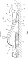
- Fig. 1 shows a milling machine on the example of a muzzle-milling machine 1a.
- the road construction machine 1 has a machine frame 2, which is supported by an existing example of crawler tracks or wheels chassis 4, which is connected via at least three height adjustment devices in the form of lifting columns 5 with the machine frame 2.
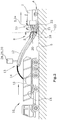
- How out Fig. 2 seen, in the embodiment, four lifting columns 5 are provided, with which the machine frame 2 can be brought into a predetermined plane, which preferably runs parallel to the road surface 6, on which the crawler tracks of the chassis 4 are.
- Fig. 1 Road milling machine shown has a work roll 22 in the longitudinal direction of the milling machine 1 a between the crawler tracks of the chassis 4.
- the milling machines 1a, 1b may have track wheels and / or wheels.
- the work roll can be height-adjustable via the lifting frame 5 carrying the machine frame 2 or relative to the machine frame 2.
- a milling machine 1 b may include the work roll 22, for example, at the level of the rear crawler tracks or wheels of the chassis 4.
- the conveyor belt device with at least one conveyor belt 11,12 for removal of the milled milled material at the front 7 or rear end 8 of the milling machine 1a, 1b may be arranged.
- Fig.2 shows the example of a back-loader milling machine 1b, in which the transport vehicle 10 travels behind in reverse drive behind the milling machine.
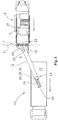
- the transport vehicle 10 can, as in Fig. 3 shown to be moved in forward drive next to the milling machine 1.
- the directions of the respective vehicles are in the FIGS. 1 to 3 each indicated by arrows.
- the milled material milled by the work roll 22 is loaded onto the loading surface 15 of the transport vehicle 10 via a first stationary conveyor belt 11 of the conveyor belt device, which transfers the milled material 14 to a second pivotable conveyor belt 12. Due to the speed of the conveyor belt 12, the milled material 14 is not unloaded directly at the end of the conveyor belt 12, but the milled material follows a pitch parabola, so that the impact point 16 is located on the loading surface 15 at a distance from the free end 13 of the conveyor belt 12.
- the conveyor belt 12 can be pivoted from a central position to the left or to the right via piston-cylinder units 18 in order to unload the material to be milled 14 even when cornering or when tracked driving the transport vehicle 10 on the loading area 15.
- the driver of the milling machine 1 a, 1 b can adjust the elevation angle of the conveyor belt 12 with the aid of a piston-cylinder unit 20.
- the elevation angle influences as well as the conveying speed the conveyor belt 12, the parcel of the milled material 14 and the position of the point of impact 16.
- the currently set elevation angle about a horizontal first axis 21 or pivot angle about a vertical second axis 23 is reported to a detection and control system 24, which further comprises at least one detector 26, the position of the loading surface 15 and / or in the transport direction Last or single conveyor belt 12 continuously detected.
- This detector 26 can either be arranged on the milling machine 1a, 1b at the end facing the conveyor belt device or at the free end 13 of the conveyor belt 12.
- the detection and control system 24 may be integrated in the controller 3 for the driving and milling operation or at least connected to this, if necessary, also data on the driving speed and / or a detected steering angle of the milling machine 1a, 1b and the conveying speed of the conveyor belt 12 to get.
- the detection and control system 24 locates the variable position of the loading surface 15 of the transport vehicle 10 and the transport direction in the last or single conveyor belt 12 relative to the machine frame 2 and controls the positioning of the impact point 16 of the material to be milled 14 on the swivel angle and / or elevation angle and / or the conveying speed of the conveyor belt device continuously and automatically, so that the discarded milled material 14 at least impinges within the loading area 15.
- the variable position of the loading area 15 of the transport vehicle 10 relative to the transport direction in the last or single conveyor belt 12 can be continuously located to perform the control.
- the detection and control system 24 takes on the task to fill the loading area 15 evenly.
- a loading program is provided to load the loading area 15 according to a predetermined system.
- the filling state on the loading surface 15 can be detected by an image acquisition system and analyzed to the conveying speed and / or to control the position of the discharge end 13 of the last or single conveyor belt 12 relative to the loading surface 15 in the transport direction.
- control data can be stored in a characteristic field for different locations and / or points of impact 16.
- a map memory may be integrated in the detection and control system 24 or in the controller 3.
- the control data relate to the swivel angle, the elevation angle and / or the conveying speed of the conveyor belt 12 for different positions and / or impact points 16 within the position of a loading area 15 detected by the detection and control system 24.
- the detection and control system 24 detects the position of the loading area 15 and / or in the transport direction last or single conveyor belt 12 continuously using an image pickup system 28 or a non-optical electronic location system, the data for determining the position of the bed 15 in relation to the machine frame 2 or to the transport direction last or single conveyor belt 12 supplies.
- the information of the image acquisition system 28 can be evaluated by known image analysis methods.
- An example of a non-optical electronic positioning system is a radio-frequency identification system (RFID), which additionally allows the possibility of identifying a specific loading area 15 of a specific transport vehicle 10.
- RFID radio-frequency identification system
- sensor nodes distributed in space are used as markers and the signal field strength, which is dependent on the distance, is measured.
- the detection and control system 24 can compare the data for determining the position with predetermined position data, in the case of deviations from the predetermined desired position data, a continuous position control for the position of the discharge end 13 and / or the impact point 16 of the material 14 and / or a speed control for the conveying speed.
- the desired position data can be determined by a teach-in method by varying the positions of the vehicles 1a, 1b, 10 in accordance with realistic situations and storing the respectively required parameters, namely the swivel angle, elevation angle and conveying speed of the conveyor belt. In the same way, a loading program can be created. There may also be variations of the control, e.g. caused by cornering, to be considered.
- the read by the reading data can also distinguish whether the transport vehicle 10 is left or right next to the milling track or in the milling track of the milling machine 1a, 1b.
Landscapes
- Engineering & Computer Science (AREA)
- Mining & Mineral Resources (AREA)
- Architecture (AREA)
- Civil Engineering (AREA)
- Structural Engineering (AREA)
- Mechanical Engineering (AREA)
- Remote Sensing (AREA)
- Radar, Positioning & Navigation (AREA)
- Aviation & Aerospace Engineering (AREA)
- Physics & Mathematics (AREA)
- General Physics & Mathematics (AREA)
- Automation & Control Theory (AREA)
- Control Of Position, Course, Altitude, Or Attitude Of Moving Bodies (AREA)
- Control Of Conveyors (AREA)
- Disintegrating Or Milling (AREA)
- Road Repair (AREA)
Description
- Die Erfindung betrifft eine selbstfahrende Fräsmaschine nach dem Oberbegriff des Anspruchs 1, sowie ein Verfahren zum Abladen von Fräsgut nach dem Oberbegriff des Anspruchs 9. Bei einer selbstfahrenden Fräsmaschine ist es bekannt, das Fräsgut auf mindestens ein Transportfahrzeug mit einer Ladefläche abzuladen.
DieEP 2 573 266 offenbart ein Verfahren zur Steuerung eines Beladungsvorgangs eines Transportfahrzeugs durch eine im Fräsbetrieb befindliche Fräsvorrichtung, eine Vorrichtung zur Durchführung dieses Verfahrens und eine Straßenfräse oder eine Vorrichtung zum Abbau von Bodenmaterial mit einer solchen Vorrichtung. Ein wesentlicher Aspekt der Erfindung liegt dabei in einer Sensoreinrichtung, mittels derer die Lage und zum Teil auch der Füllstand des Transportbehältnisses des Transportfahrzeuges bestimmt werden kann.
Des Weiteren offenbart dieDE20 2007 005 765 U1 eine Straßenfräse mit Überwachunskameras.
Die Fräsmaschine weist eine Steuerung für den Fahr- und Fräsbetrieb auf sowie eine Arbeitswalze zum Fräsen z.B. eines Straßenbelages. Vor oder hinter der Arbeitswalze - in Fahrtrichtung gesehen - befindet sich eine Transportbandeinrichtung, z.B. eine Transportbandeinrichtung mit mindestens einem Transportband. Die Transportbandeinrichtung weist ein Abwurfende auf, an dem das Fräsgut aufgrund der Fördergeschwindigkeit über eine Flugbahn in Form einer Wurfparabel auf die Ladefläche des mindestens einen Transportfahrzeugs abgeladen wird. Das in Transportrichtung letzte oder einzige Transportband der Transportbandeinrichtung kann relativ zur Längsachse der Fräsmaschine seitlich unter einem vorgebbaren Schwenkwinkel nach links oder rechts verschwenkt werden und über einen vorgebbaren Höhenwinkel höhenverstellbar sein. - Im praktischen Betrieb entstehen Probleme bei der Koordination der Fräsmaschine mit dem Transportfahrzeug.
- Beispielsweise wird bei einer Vorderlader-Fräsmaschine das Fräsgut nach vorne auf das vorausfahrende Transportfahrzeug abgeworfen. Die Bedienungsperson für die Fräsmaschine muss dem Fahrzeugführer des Transportfahrzeuges signalisieren, wann sich das Transportfahrzeug weiter nach vorne bewegen soll. Dies führt zu Problemen, weil sich die Bedienungsperson im Grunde genommen auf den Fräsbetrieb konzentrieren muss und gleichzeitig eine Kollision mit dem vorausfahrenden Transportfahrzeug vermeiden muss. Üblicherweise geschieht die Vermittlung der Information über ein Hupen, so dass, sobald der Fahrzeugführer des Transportfahrzeugs das Hupen vernimmt, das Transportfahrzeug um eine bestimmte Wegstrecke vorbewegt wird. Problematisch ist dabei die Situation, in der der Fahrzeugführer des Transportfahrzeugs das Hupsignal überhört, oder wenn ein anderes vorbeifahrendes Fahrzeug ein Hupsignal abgibt, so dass der Fahrzeugführer des Transportfahrzeugs irrtümlich meint, sein Fahrzeug vorbewegen zu müssen. Überhört der Fahrzeugführer das Hupsignal, kann es zu einer Kollision des schwenkbaren Transportbandes der Transportbandeinrichtung mit dem Transportfahrzeug kommen, oder die Bedienungsperson der Fräsmaschine muss den kontinuierlichen Fräsbetrieb stoppen.
- Ein weiteres Problem besteht darin, dass die Bedienungsperson für die Fräsmaschine auch die Beladung der Ladefläche durch Verstellung des Schwenkwinkels, des Höhenwinkels und der Fördergeschwindigkeit des in Transportrichtung letzten oder einzigen Transportbandes der Transportbandeinrichtung übernehmen muss und dadurch von seiner eigentlichen Aufgabe, den Fräsbetrieb durchzuführen, abgelenkt wird. Eine Korrektur des Schwenkwinkels kann beispielsweise bei einem Wechsel der Lenkrichtung der Fräsmaschine notwendig sein.
- Auch im Falle einer Hinterlader-Fräsmaschine bestehen Probleme bei der Koordination der Fräsmaschine mit dem Transportfahrzeug, zumal das Transportfahrzeug hinter der Fräsmaschine in Rückwärtsfahrt hinterherfahren muss. Für die Bedienungsperson der Fräsmaschine ergibt sich eine noch höhere Belastung, da sie einerseits den Fräsbetrieb in Vorwärtsfahrt steuern muss und andererseits die Beladung des Transportfahrzeugs in Fahrtrichtung hinter der Fräsmaschine beobachten muss, den Schwenkwinkel, den Höhenwinkel und/oder die Fördergeschwindigkeit der Transportbandeinrichung steuern muss und dem Fahrzeugführer die notwendigen Informationen vermitteln muss.
- Der Erfindung liegt daher die Aufgabe zugrunde, eine selbstfahrende Fräsmaschine , sowie ein Verfahren zum Abladen von Fräsgut einer Fräsmaschine zu schaffen, das eine automatische Koordination des Abladevorgangs der im Fräsbetrieb befindlichen Fräsmaschine mit der Bewegung des Transportfahrzeugs ermöglicht.
- Zur Lösung dieser Aufgabe dienen die Merkmale der Ansprüche 1 bzw. 9. Die Erfindung sieht vor, dass die Steuerung ein Erfassungs- und Steuerungssystem aufweist, das die veränderliche Lage der Ladefläche des Transportfahrzeugs relativ zum schwenkbaren Transportband fortlaufend ortet und die Positionierung der Auftreffstelle des Fräsgutes über den Schwenkwinkel und/oder den Höhenwinkel und/oder die Fördergeschwindigkeit des schwenkbaren Transportbandes derart fortlaufend automatisch steuert, dass das abgeworfene Fräsgut innerhalb der Ladefläche auftrifft.
Eine derartige Steuerung ermöglicht es, dass sich die Bedienungsperson der Fräsmaschine auf den Fräsbetrieb und die Fahrt entlang einer vorgegebenen Frässpur konzentrieren kann. Auf diese Weise ist ein automatischer Abladevorgang realisiert, der auch bei Kurvenfahrt für eine automatische Koordination des Abladevorgangs mit der Bewegung der Fräsmaschine und des Transportfahrzeugs sorgt. Beispielsweise kann auch der Schwenkwinkel des in Transportrichtung letzten oder einzigen Transportbandes der Transportbandeinrichtung in Abhängigkeit vom Lenkwinkel der selbstfahrenden Fräsmaschine steuerbar sein. Erfindungsgemäß ist vorgesehen, dass das Erfassungs- und Steuerungssystem die Positionierung der Auftreffstelle des Fräsgutes derart fortlaufend automatisch steuert, dass das abgeworfene Fräsgut auf die Mitte der Ladefläche oder eine andere vorgebbare Auftreffstelle innerhalb der Ladefläche auftrifft.
Die Ladefläche kann geortet werden und die Lage des Transportbandes und die Fördergeschwindigkeit des schwenkbaren Transportbandes derart geregelt werden, dass die Auftreffstelle auf der Ladefläche unabhängig von den Bewegungen der Fräsmaschine und des Transportfahrzeugs stets an der von der Steuerung vorgegebenen Stelle gehalten wird. - Das Erfassung- und Steuerungssystem weist mindestens einen Detektor auf, der die Lage der Ladefläche und/oder des schwenkbaren Transportbandes der Transportbandeinrichtung fortlaufend detektiert, und/oder weitere Detektoren aufweisen, die den Schwenkwinkel, den Höhenwinkel und/oder die Fördergeschwindigkeit des Transportbandes detektieren.
Bei einem bevorzugten Ausführungsbeispiel ist vorgesehen, dass das Erfassungs- und Steuerungssystem die Lage der Ladefläche und/oder des in Transportrichtung letzten oder einzigen Transportbandes der Transportbandeinrichtung fortlaufend mit Hilfe eines ersten Bildaufnahmesystems oder eines nicht optischen elektronischen Ortungssystems, insbesondere eines Radiofrequenzidentifikationssystems (RFID), ortet, das Daten zur Lagebestimmung der Ladefläche in Relation zum Maschinenrahmen oder zu dem schwenkbaren Transportband liefert.
Das Erfassungs- und Steuerungssystem kann die Daten zur Lagebestimmung mit vorgegebenen Soll-Lagedaten vergleichen, um im Falle von Abweichungen von den vorgegebenen Soll-Lagedaten eine fortlaufende Lagesteuerung für die Lage eines Abwurfendes und/oder der Auftreffstelle des Fräsgutes und/oder eine Geschwindigkeitssteuerung für die Fördergeschwindigkeit entsprechend einer vorgegebenen Auftreffstelle durchzuführen.
Das Erfassungs- und Steuerungssystem kann ein zweites Bildaufnahmesystem aufweisen, das den Befüllungszustand auf der Ladefläche durch Auswertung der Bilddaten erfasst und analysiert, und die Fördergeschwindigkeit und/oder die Lage eines Abwurfendes und/oder der Auftreffstelle des Fräsgutes relativ zur Ladefläche fortlaufend steuert, um die Ladefläche gleichmäßig und/oder nach einem vorgegebenen Beladungsprogramm zu beladen. Ein zweites Bildaufnahmesystem kann entfallen, wenn bereits zur Ortung der Lage der Ladefläche ein Bildaufnahmesystem zum Einsatz kommt, dessen Bilddaten zur Detektion des Befüllungszustandes ebenfalls herangezogen werden können. - Das Erfassungs- und Steuerungssystem kann die Lage der Ladefläche orten, sowie die Lage des in Transportrichtung letzten oder einzigen Transportbandes der Transportbandeinrichtung oder die Position der Auftreffstelle und die Fördergeschwindigkeit derart regeln, dass die Auftreffstelle auf der Ladefläche unabhängig von den Bewegungen der Fräsmaschine und des Transportfahrzeugs stets an der von der Steuerung vorgegebenen Stelle innerhalb der Ladefläche gehalten ist.
- Das erste und/oder zweite Bildaufnahmesystem oder ein Detektor für das Radiofrequenzidentifikationssystems (RFID) können am Abwurfende der in Förderrichtung des Fräsgutes einzigen oder letzten Transportbandes angeordnet sein.
- Die Anordnung eines solchen Ortungssystems am Abwurfende des Transportbandes ermöglicht es, die relative Lage des Transportfahrzeugs zu dem in Transportrichtung letzten oder einzigen Transportband Fräsmaschine zu erfassen, ohne dass zusätzlich die Lage der Fräsmaschine festgestellt werden muss.
- Außerdem können die Bilddaten dahingehend analysiert werden, wie und in welchem Umfang die Ladefläche befüllt ist. Durch Steuerung der Fördergeschwindigkeit und/oder der Lage des Abwurfendes des Transportbandes, bzw. der Auftreffstelle des Fräsgutes relativ zur Ladefläche kann die Ladefläche gleichmäßig beladen werden. Der Befüllungszustand auf der Ladefläche kann von einem Bildaufnahmesystem erfasst und analysiert werden und die Fördergeschwindigkeit und/oder die Lage des Abwurfendes des Transportbandes relativ zur Ladefläche fortlaufend gesteuert werden, um die Ladefläche gleichmäßig und/oder nach einem vorgegebenen Beladungsprogramm zu beladen.
- Es kann jedoch auch vorteilhaft sein, die Auftreffstelle auf der Ladefläche zu variieren, um eine gleichförmige Beladung der Ladefläche zu erreichen.
- Es ist vorgesehen, dass das Erfassungs- und Steuerungssystem über die Verstellung des seitlichen Schwenkwinkels des schwenkbaren Transportbandes der Transportbandeinrichtung relativ zur Fahrtrichtung und die Verstellung des Höhenwinkels des schwenkbaren Transportbandes der Transportbandeinrichtung die Lage des Abwurfendes der Transportbandeinrichtung und damit der Auftreffstelle auf der Ladefläche steuert.
Das Erfassungs- und Steuerungssystem kann vor oder spätestens bei einer steuerungsmäßig nicht korrigierbaren Abweichung der Lage der Ladefläche relativ zur Lage des in Transportrichtung letzten oder einzigen Transportbandes der Transportbandeinrichtung und/oder des Maschinenrahmens ein Signal abgeben. Das Signal kann verwendet werden, um einen Maschinenstillstand herbeizuführen oder Maßnahmen zu treffen, um Kollisionen zwischen den Fahrzeugen zu vermeiden.
In Abhängigkeit von Ladeflächen unterschiedlicher Transportfahrzeuge und/oder in Abhängigkeit unterschiedlicher Beladungszustände der Ladefläche für unterschiedliche Lagen und/oder Auftreffstellen innerhalb der von dem Erfassungs- und Steuerungssystem erfassten Lage einer Ladefläche können Steuerungsdaten für den Schwenkwinkel, den Höhenwinkel und/oder die Fördergeschwindigkeit in einem Kennfeld gespeichert sein, das dem Erfassungs- und Steuerungssystem zur Verfügung steht. Mit Hilfe eines RFID-Systems können beispielsweise Ladeflächen unterschiedlicher Transportfahrzeuge identifiziert werden.
Mindestens eine Stelle der in der Regel im Wesentlichen rechteckigen Ladefläche, bzw. im Wesentlichen quaderförmigen Ladevolumens kann eine von dem Erfassungs- und Steuerungssystem detektierbare Markierung tragen.
Es kann ein Fortbewegungs-Steuerungssignal z. B. ein optisches oder akustisches Signal in Abhängigkeit von den Ortungssignalen erzeugt werden. Fortbewegungs-Steuerungssignale für das Transportfahrzeug sind grundsätzlich in derDE 10 2009 041 842 A1 beschrieben. - Zur Lösung der Aufgabe dienen auch die Merkmale des Anspruchs 9. Nach dem erfindungsgemäßen Verfahren ist vorgesehen, dass die veränderliche Lage der Ladefläche des Transportfahrzeugs relativ zu dem in Transportrichtung letzten oder einzigen Transportbandes fortlaufend von einem Erfassungs- und Steuerungssystem geortet wird und dass die Positionierung der Auftreffstelle des Fräsgutes über den Schwenkwinkel und/oder den Höhenwinkel und/oder die Fördergeschwindigkeit der Transportbandeinrichtung derart von dem Erfassungs- und Steuerungssystem fortlaufend automatisch gesteuert wird, dass das Fräsgut innerhalb der Ladefläche abgeworfen wird.
- Die Positionierung der Auftreffstelle des Fräsgutes wird erfindungsgemäß derart von dem Erfassungs- und Steuerungssystem fortlaufend automatisch gesteuert werden, dass das Fräsgut auf die Mitte der Ladefläche oder eine andere vorgebbare Auftreffstelle innerhalb der Ladefläche abgeworfen wird.
Die Lage der Ladefläche und/oder des in Transportrichtung letzten oder einzigen Transportbandes der Transportbandeinrichtung kann fortlaufend mit Hilfe eines Bildaufnahmesystems oder eines nicht optischen elektronischen Ortungssystems, insbesondere eines Radiofrequenzidentifikationssystems (RFID), geortet werden, das Daten zur Lagebestimmung der Ladefläche in Relation zum Maschinenrahmen oder zu dem in Transportrichtung letzten oder einzigen Transportbandes liefert.
Bei einem Ausführungsbeispiel kann ein Bild zur Lagebestimmung der Ladefläche in Relation zu dem Abwurfende des Transportbandes und/oder zur Bestimmung des Befüllungszustandes der Ladefläche von einem Bildaufnahmesystem mit einer vorgegebenen Abtastfrequenz aufgenommen und analysiert werden. Die analysierten Daten werden mit Soll-Lagewerten verglichen, und im Falle von festgestellten Abweichungen die Lage des Abwurfendes des Transportbandes und/oder die Fördergeschwindigkeit und/oder die Position des Transportfahrzeuges gesteuert werden.
Die Soll-Lagedaten können durch ein teach-in Verfahren ermittelt werden. - Die Position der geometrischen Mitte der Ladefläche kann durch Bildanalyse oder durch das nicht optische Ortungssystem und die Position der aktuellen Auftreffstelle auf der Ladefläche durch Bildanalyse ermittelt werden und eine Positionssteuerung der Lage des Abwurfendes und/oder der Auftreffstelle des Fräsgutes und eine Geschwindigkeitssteuerung der Fördergeschwindigkeit des Transportbandes in Abhängigkeit von der gewünschten Position der Auftreffstelle durchgeführt werden, so dass eine fortlaufende Regelung der Position der aktuellen Auftreffstelle durchgeführt wird.
- Im Folgenden werden unter Bezugnahme auf die Zeichnungen Ausführungsbeispiele der Erfindung näher erläutert.
- Es zeigen:
- Fig. 1
- eine Vorderlader-Straßenfräsmaschine,
- Fig. 2
- eine Hinterlader-Straßenfräsmaschine, und
- Fig. 3
- eine Draufsicht auf eine Fräsmaschine gemäß
Fig. 1 . -
Fig. 1 zeigt eine Fräsmaschine am Beispiel einer Vorderlader-Straßenfräsmaschine 1a. Die Straßenbaumaschine 1 weist einen Maschinenrahmen 2 auf, der von einem beispielsweise aus Kettenlaufwerken oder Rädern bestehenden Fahrwerk 4 getragen wird, das über mindestens drei Höhenverstelleinrichtungen in Form von Hubsäulen 5 mit dem Maschinenrahmen 2 verbunden ist. Wie ausFig. 2 ersichtlich, sind bei dem Ausführungsbeispiel vier Hubsäulen 5 vorgesehen, mit denen der Maschinenrahmen 2 in eine vorgebbare Ebene gebracht werden kann, die vorzugsweise parallel zur Straßenoberfläche 6 verläuft, auf denen die Kettenlaufwerke des Fahrwerks 4 stehen. - Die in
Fig. 1 gezeigte Straßenfräsmaschine weist eine Arbeitswalze 22 in Längsrichtung der Fräsmaschine 1a zwischen den Kettenlaufwerken des Fahrwerks 4 auf. - Die Fräsmaschinen 1a, 1b können Kettenlaufräder und/oder Räder aufweisen. Die Arbeitswalze kann über die den Maschinenrahmen 2 tragenden Hubsäulen 5 oder relativ zu dem Maschinenrahmen 2 höhenverstellbar sein.
- Andere Bauformen einer Fräsmaschine 1b können die Arbeitswalze 22 beispielsweise auch in Höhe der hinteren Kettenlaufwerke oder Räder des Fahrwerks 4 aufweisen.
- Ebenso kann die Transportbandeinrichtung mit mindestens einem Transportband 11,12 zum Abtransport des abgefrästen Fräsgutes am vorderen 7 oder hinteren Ende 8 der Fräsmaschine 1a, 1b angeordnet sein.
-
Fig.2 zeigt das Beispiel einer Hinterlader-Fräsmaschine 1b, bei der das Transportfahrzeug 10 in Rückwärtsfahrt hinter der Fräsmaschine hinterherfährt. - Sofern seitlich neben der Fräsmaschine 1a, 1b ausreichend Platz zur Verfügung steht, kann das Transportfahrzeug 10, wie in
Fig. 3 gezeigt, auch in Vorwärtsfahrt neben der Fräsmaschine 1 bewegt werden.
Die Fahrtrichtungen der jeweiligen Fahrzeuge sind in denFign. 1 bis 3 jeweils durch Pfeile angezeigt. - Bei dem Ausführungsbeispiel der
Fig. 1 wird das von der Arbeitswalze 22 abgefräste Fräsgut über ein erstes ortsfestes Transportband 11 der Transportbandeinrichtung, das das Fräsgut 14 auf ein zweites schwenkbares Transportband 12 überträgt, auf die Ladefläche 15 des Transportfahrzeugs 10 abgeladen. Aufgrund der Geschwindigkeit des Transportbandes 12 wird das Fräsgut 14 nicht unmittelbar am Ende des Transportbandes 12 abgeladen, sondern das Fräsgut folgt einer Wurfparabel, so dass die Auftreffstelle 16 auf der Ladefläche 15 mit Abstand von dem freien Ende 13 des Transportbandes 12 befindlich ist. Das Transportband 12 kann aus einer Mittelposition heraus nach links oder nach rechts über Kolben-Zylindereinheiten 18 verschwenkt werden, um das Fräsgut 14 auch bei Kurvenfahrt bzw. bei spurversetztem Fahren des Transportfahrzeugs 10 auf die Ladefläche 15 abladen zu können. Des Weiteren kann der Fahrzeugführer der Fräsmaschine 1a, 1b den Höhenwinkel des Transportbandes 12 mit Hilfe einer KolbenZylindereinheit 20 einstellen. Der Höhenwinkel beeinflusst ebenso wie die Fördergeschwindigkeit des Transportbandes 12, die Wurfparabel des Fräsgutes 14 und die Position der Auftreffstelle 16.
Der aktuell eingestellte Höhenwinkel um eine horizontale erste Achse 21 bzw. Schwenkwinkel um eine vertikale zweite Achse 23 wird an ein Erfassungs- und Steuerungssystem 24 gemeldet, das des Weiteren mindestens einen Detektor 26 aufweist, der die Lage der Ladefläche 15 und/oder des in Transportrichtung letzten oder einzigen Transportbandes 12 fortlaufend detektiert. Dieser Detektor 26 kann entweder an der Fräsmaschine 1a, 1b an dem der Transportbandeinrichtung zugewandten Ende oder an dem freien Ende 13 des Transportbandes 12 angeordnet sein.
Das Erfassungs- und Steuerungssystem 24 kann in die Steuerung 3 für den Fahr- und Fräsbetrieb integriert sein oder mit dieser zumindest verbunden sein, um ggf. auch Daten über die Fahrgeschwindigkeit und/oder einen detektierten Lenkwinkel der Fräsmaschine 1a,1b und die Fördergeschwindigkeit des Transportbandes 12 zu erhalten.
Das Erfassungs- und Steuerungssystem 24 ortet die veränderliche Lage der Ladefläche 15 des Transportfahrzeugs 10 und des in Transportrichtung letzten oder einzigen Transportbandes 12 relativ zum Maschinenrahmen 2 und steuert die Positionierung der Auftreffstelle 16 des Fräsgutes 14 über den Schwenkwinkel und/oder den Höhenwinkel und/oder die Fördergeschwindigkeit der Transportbandeinrichtung fortlaufend und automatisch, so dass das abgeworfene Fräsgut 14 zumindest innerhalb der Ladefläche 15 auftrifft. Alternativ kann auch die veränderliche Lage der Ladefläche 15 des Transportfahrzeugs 10 relativ zu dem in Transportrichtung letzten oder einzigen Transportband 12 fortlaufend geortet werden, um die Steuerung durchzuführen. - Das Erfassungs- und Steuerungssystem 24 übernimmt erfindungsgemäß die Aufgabe, die Ladefläche 15 gleichmäßig zu befüllen. Hierzu ist ein Beladungsprogramm vorgesehen, um die Ladefläche 15 nach einem vorbestimmten System zu beladen. Dabei kann der Befüllungszustand auf der Ladefläche 15 von einem Bildaufnahmesystem erfasst und analysiert werden, um die Fördergeschwindigkeit und/oder die Lage des Abwurfendes 13 des in Transportrichtung letzten oder einzigen Transportbandes 12 relativ zur Ladefläche 15 fortlaufend zu steuern.
- In Abhängigkeit von Ladeflächen 15 unterschiedlicher Transportfahrzeuge 10 und/oder in Abhängigkeit unterschiedlicher Beladungszustände der Ladefläche 15 können für unterschiedliche Lagen und/oder Auftreffstellen 16 Steuerungsdaten in einem Kennfeld gespeichert sein. Ein solcher Kennfeld-Speicher kann in das Erfassungs- und Steuerungssystem 24 oder in der Steuerung 3 integriert sein. Die Steuerungsdaten betreffen den Schwenkwinkel, den Höhenwinkel und/oder die Fördergeschwindigkeit des Transportbandes 12 für unterschiedliche Lagen und/oder Auftreffstellen 16 innerhalb der von den Erfassungs- und Steuerungssystem 24 erfassten Lage einer Ladefläche 15.
- Das Erfassungs- und Steuerungssystem 24 erfasst die Lage der Ladefläche 15 und/oder des in Transportrichtung letzten oder einzigen Transportbandes 12 fortlaufend mit Hilfe eines Bildaufnahmesystems 28 oder eines nicht optischen elektronischen Ortungssystems, das Daten zur Lagebestimmung der Ladefläche 15 in Relation zu dem Maschinenrahmen 2 oder zu dem in Transportrichtung letzten oder einzigen Transportbandes 12 liefert. Die Informationen des Bildaufnahmesystems 28 kann durch für sich bekannte Bildanalysemethoden ausgewertet werden. Ein Beispiel für ein nicht optisches elektronisches Ortungssystems ist ein Radiofrequenz-Identifikationssystem (RFID), das zusätzlich noch die Möglichkeit der Identifikation einer bestimmten Ladefläche 15 eines bestimmten Transportfahrzeugs 10 ermöglicht.
- Bei der Lokalisierung der Ladefläche 15 mit RFID werden stationäre RFID-Tags an dem Transportfahrzeug 10 insbesondere an der Ladefläche 15 verwendet.
- Bei einer Lokalisierung mit Bluetooth-Sensorknoten als weiteres nicht optisches Lokalisierungsverfahren werden im Raum verteilte Sensorknoten als Markierungen verwendet und die Signalfeldstärke, die abhängig von der Entfernung ist, gemessen.
- Selbstverständlich besteht auch die Möglichkeit, unterschiedliche Lokalisierungsverfahren in Kombination zu verwenden.
- Generell kann mit optischen und quasi-optischen (Funk-) Messmethoden für Länge und Winkel, sowie mit verschiedenen Zeitmessverfahren für Zeitdifferenzen und Laufzeitdifferenzen gearbeitet werden.
- Das Erfassungs- und Steuerungssystem 24 kann die Daten zur Lagebestimmung mit vorgegebenen Lagedaten vergleichen, um im Falle von Abweichungen von den vorgegebenen Soll-Lagedaten eine fortlaufende Lagesteuerung für die Position des Abwurfendes 13 und/oder der Auftreffstelle 16 des Fräsgutes 14 und/oder eine Geschwindigkeitssteuerung für die Fördergeschwindigkeit durchzuführen.
- Die Soll-Lagedaten können durch ein Teach-in-Verfahren ermittelt werden, indem die Positionen der Fahrzeuge 1a,1b,10 entsprechend realistischen Situationen variiert werden und die jeweils hierfür notwendigen Parameter, nämlich Schwenkwinkel, Höhenwinkel und Fördergeschwindigkeit des Transportbandes gespeichert werden. In gleicher Weise kann auch ein Beladungsprogramm erstellt werden. Dabei können auch Variationen der Steuerung, die z.B. durch Kurvenfahrt entstehen, berücksichtigt werden. Die durch den Lesevorgang eingelesenen Daten können dabei auch unterscheiden, ob das Transportfahrzeug 10 links oder rechts neben der Frässpur fährt oder in der Frässpur der Fräsmaschine 1a, 1b.
Claims (12)
- Selbstfahrende Fräsmaschine (1a,1b),- mit einem höhenverstellbaren Maschinenrahmen (2),- mit einer Steuerung (3) für den Fahr- und Fräsbetrieb,- mit einer Arbeitswalze (22),- mit einem in Fahrtrichtung der Fräsmaschine (1a,1b) vor oder hinter der Arbeitswalze (22) angeordneten schwenkbaren letzten oder einzigen Transportband (12) einer Transportbandeinrichtung,- wobei das Transportband (12) relativ zum Maschinenrahmen (2) um eine im wesentlichen horizontal verlaufende erste Achse (21) unter einem Höhenwinkel, und um eine orthogonal zur ersten Achse (20) verlaufende zweite Achse (23) seitlich unter einem Schwenkwinkel verschwenkbar ist,- wobei das Transportband (12) das Fräsgut mit einer vorgegebenen Fördergeschwindigkeit auf eine Auftreffstelle (16) auf einer Ladefläche (15) eines Transportfahrzeugs (10) ablädt, und- wobei ein am freien Ende des Transportbandes (12) angeordneter Detektor (26) eines Erfassungs- und Steuerungssystems die Lage der Ladefläche (15) fortlaufend detektiert,dadurch gekennzeichnet,dass
die Steuerung (3) das Erfassungs- und Steuerungssystem (24) aufweist, das die veränderliche Lage der Ladefläche (15) des Transportfahrzeugs (10) relativ zum Transportband (12) fortlaufend ortet und die Positionierung der Auftreffstelle (16) des Fräsgutes (14) über den Schwenkwinkel und/oder den Höhenwinkel, welche dem Erfassungs- und Steuerungssystem (24) wie aktuell eingestellt gemeldet werden, und/oder die Fördergeschwindigkeit der Transportbandeinrichtung (12) derart fortlaufend automatisch steuert, dass das abgeworfene Fräsgut (14) auf die Mitte der Ladefläche (15) oder eine andere vorgebbare Auftreffstelle (16) innerhalb der Ladefläche (15) auftrifft, wobei ein Beladungsprogramm vorgesehen ist, mittels dessen die Ladefläche gleichmässig nach einem vorbestimmten System beladen werden kann. - Vorrichtung nach Anspruch 1, dadurch gekennzeichnet, dass das Erfassungs- und Steuerungssystem (24) mindestens einen Detektor (26) aufweist, der die Lage der Ladefläche (15) und/oder des Transportbandes (12) fortlaufend detektiert, und/oder weitere Detektoren aufweist, die den Schwenkwinkel, den Höhenwinkel und/oder die Fördergeschwindigkeit der Transportbandeinrichtung (12) detektieren.
- Vorrichtung nach einem der Ansprüche 1 oder 2, dadurch gekennzeichnet, dass das Erfassungs- und Steuerungssystem (24) die Lage der Ladefläche (15) und/oder des Transportbandes (12) fortlaufend mit Hilfe eines ersten Bildaufnahmesystems (28) oder eines nicht optischen elektronischen Ortungssystems, insbesondere eines Radiofrequenzidentifikationssystems (RFID), ortet, das Daten zur Lagebestimmung der Ladefläche (15) in Relation zum Maschinenrahmen (2) oder zum Transportband (12) liefert.
- Vorrichtung nach Anspruch 3, dadurch gekennzeichnet, dass das Erfassungs- und Steuerungssystem (24) die Daten zur Lagebestimmung mit vorgegebenen Soll-Lagedaten vergleicht, um im Falle von Abweichungen von den vorgegebenen Soll-Lagedaten eine fortlaufende Lagesteuerung für die Position eines Abwurfendes (13) der Transportbandeinrichtung (12) und/oder der Auftreffstelle (16) und/oder eine Geschwindigkeitssteuerung für die Fördergeschwindigkeit entsprechend einer vorgegebenen Auftreffstelle (16) durchzuführen.
- Vorrichtung nach einem der Ansprüche 3 oder 4, dadurch gekennzeichnet, dass das Bildaufnahmesystem (28) oder ein Detektor für das Radiofrequenzidentifikationssystems (RFID) am Abwurfende (13) des in Förderrichtung des Fräsgutes (14) einzigen oder letzten Transportbandes (12) angeordnet ist.
- Vorrichtung nach einem der Ansprüche 1 bis 5, dadurch gekennzeichnet, dass das Erfassungs- und Steuerungssystem (24) vor oder spätestens bei einer steuerungsmäßig nicht korrigierbaren Abweichung der Lage der Ladefläche (15) relativ zur Lage des Transportbandes (12) und/oder des Maschinenrahmens (2) ein Signal abgibt.
- Vorrichtung nach einem der Ansprüche 1 bis 6, dadurch gekennzeichnet, dass in Abhängigkeit von Ladeflächen (15) unterschiedlicher Transportfahrzeuge (10) und/oder in Abhängigkeit unterschiedlicher Beladungszustände der Ladefläche (15) für unterschiedliche Lagen und/oder Auftreffstellen (16) innerhalb der von dem Erfassungs- und Steuerungssystem (24) erfassten Lage einer Ladefläche (15) Steuerungsdaten für den Schwenkwinkel, den Höhenwinkel und/oder die Fördergeschwindigkeit in einem Kennfeld gespeichert sind.
- Vorrichtung nach einem der Ansprüche 1 bis 7, dadurch gekennzeichnet, dass mindestens eine Stelle der im Wesentlichen rechteckigen Ladefläche (15), oder im Wesentlichen quaderförmigen Ladevolumens (15) eine von dem Erfassungs- und Steuerungssystem (24) detektierbare Markierung trägt.
- Verfahren zum Abladen von abgearbeitetem Fräsgut (14) einer selbstfahrenden Fräsmaschine (1a,1b) auf eine Auftreffstelle (16) auf einer Ladefläche (15) eines Transportfahrzeuges (10), bei dem- die Fräsmaschine (1a,1b) für den Fahr- und Fräsbetrieb gesteuert wird,- das von einer Arbeitswalze abgearbeitete Fräsgut (14) mit einer in Fahrtrichtung der Fräsmaschine (1a,1b) vor oder hinter der Arbeitswalze angeordneten Transportbandeinrichtung auf die Ladefläche (15) eines Transportfahrzeugs (10) mit einer vorgegebenen Fördergeschwindigkeit abgeworfen wird, und- ein letztes oder einziges Transportband (12) der Transportbandeinrichtung relativ zum Maschinenrahmen (2) der Fräsmaschine (1a,1b) seitlich unter einem Schwenkwinkel verschwenkt und hinsichtlich der Abwurfhöhe unter einem Höhenwinkel verstellt wird, und- die Lage der Ladefläche (15) mit einem am freien Ende des Transportbandes angeordneten Detektor eines Erfassungs- und Steuerungssystems detektiert wird,dadurch gekennzeichnet,dass
die veränderliche Lage der Ladefläche (15) des Transportfahrzeugs (10) relativ zum Transportband (12) fortlaufend von dem Erfassungs- und Steuerungssystem (24) geortet wird und dass die Positionierung der Auftreffstelle (16) des Fräsgutes (14) über den Schwenkwinkel und/oder den Höhenwinkel, welche dem Erfassungs- und Steuerungssystem wie aktuell eingestellt gemeldet werden, und/oder die Fördergeschwindigkeit der Transportbandeinrichtung (12) derart von dem Erfassungs- und Steuerungssystem (24) fortlaufend automatisch gesteuert wird, dass das Fräsgut auf die Mitte der Ladefläche (15) oder eine andere vorgegebene Auftreffstelle (16) innerhalb der Ladefläche (15) nach einem vorgegebenen Beladungsprogramm gleichmässig nach einem vorbestimmten System abgeworfen wird. - Verfahren nach Anspruch 9, dadurch gekennzeichnet, dass die Lage der Ladefläche (15) und/oder des Transportbandes (12) fortlaufend geortet wird, wobei Daten zur Lagebestimmung der Ladefläche (15) in Relation zum Maschinenrahmen (2) oder zum Transportband (12) erzeugt werden und mit gespeicherten Soll-Lagedaten verglichen werden, wobei dann bei festgestellten Abweichungen die Lage des Abwurfendes (13) des Transportbandes (12), und/oder die Fördergeschwindigkeit des Transportbandes (12) und/oder die Position des Transportfahrzeuges (10) gesteuert wird, wobei die Soll-Lagedaten vorzugsweise durch ein teach-in Verfahren ermittelt werden.
- Verfahren nach einem der Ansprüche 9 bis 10, dadurch gekennzeichnet, dass die Ladefläche (15) geortet wird und die Lage und die Fördergeschwindigkeit des Transportbandes (12) derart geregelt wird, dass die Auftreffstelle (16) auf der Ladefläche (15) unabhängig von den Bewegungen der Fräsmaschine (1a, 1b) und des Transportfahrzeugs (10) stets an der von der Steuerung (3) vorgegebenen Stelle gehalten wird.
- Verfahren nach einem der Ansprüche 9 bis 11, dadurch gekennzeichnet, dass die Position der geometrischen Mitte der Ladefläche (15) durch Bildanalyse oder durch das nicht optische Ortungssystem und die Position der aktuellen Auftreffstelle (16) auf der Ladefläche (15) durch Bildanalyse ermittelt wird und eine Positionssteuerung der Position des Abwurfendes (13) des Transportbandes (12) und/oder der Auftreffstelle (16) und eine Geschwindigkeitssteuerung der Fördergeschwindigkeit des Transportbandes (12) in Abhängigkeit von der gewünschten Position der Auftreffstelle (16) durchgeführt wird, so dass eine fortlaufende Regelung der Position der aktuellen Auftreffstelle (16) durchgeführt wird.
Priority Applications (1)
| Application Number | Priority Date | Filing Date | Title |
|---|---|---|---|
| EP17204074.3A EP3342932B1 (de) | 2012-08-23 | 2013-08-21 | Selbstfahrende fräsmaschine, sowie verfahren zum abladen von fräsgut |
Applications Claiming Priority (2)
| Application Number | Priority Date | Filing Date | Title |
|---|---|---|---|
| DE102012215013.7A DE102012215013A1 (de) | 2012-08-23 | 2012-08-23 | Selbstfahrende Fräsmaschine, sowie Verfahren zum Abladen von Fräsgut |
| PCT/EP2013/067418 WO2014029824A1 (de) | 2012-08-23 | 2013-08-21 | Selbstfahrende fräsmaschine, sowie verfahren zum abladen von fräsgut |
Related Child Applications (1)
| Application Number | Title | Priority Date | Filing Date |
|---|---|---|---|
| EP17204074.3A Division EP3342932B1 (de) | 2012-08-23 | 2013-08-21 | Selbstfahrende fräsmaschine, sowie verfahren zum abladen von fräsgut |
Publications (2)
| Publication Number | Publication Date |
|---|---|
| EP2888409A1 EP2888409A1 (de) | 2015-07-01 |
| EP2888409B1 true EP2888409B1 (de) | 2017-11-29 |
Family
ID=49029098
Family Applications (2)
| Application Number | Title | Priority Date | Filing Date |
|---|---|---|---|
| EP13752630.7A Active EP2888409B1 (de) | 2012-08-23 | 2013-08-21 | Selbstfahrende fräsmaschine, sowie verfahren zum abladen von fräsgut |
| EP17204074.3A Active EP3342932B1 (de) | 2012-08-23 | 2013-08-21 | Selbstfahrende fräsmaschine, sowie verfahren zum abladen von fräsgut |
Family Applications After (1)
| Application Number | Title | Priority Date | Filing Date |
|---|---|---|---|
| EP17204074.3A Active EP3342932B1 (de) | 2012-08-23 | 2013-08-21 | Selbstfahrende fräsmaschine, sowie verfahren zum abladen von fräsgut |
Country Status (9)
| Country | Link |
|---|---|
| US (4) | US20150218762A1 (de) |
| EP (2) | EP2888409B1 (de) |
| JP (1) | JP6050493B2 (de) |
| CN (2) | CN203700926U (de) |
| AU (1) | AU2013305023B2 (de) |
| CA (1) | CA2882583C (de) |
| DE (1) | DE102012215013A1 (de) |
| RU (1) | RU2610042C2 (de) |
| WO (1) | WO2014029824A1 (de) |
Families Citing this family (35)
| Publication number | Priority date | Publication date | Assignee | Title |
|---|---|---|---|---|
| DE102013214675A1 (de) | 2013-07-26 | 2015-01-29 | Wirtgen Gmbh | Selbstfahrende Straßenfräsmaschine, sowie Verfahren zum Abfräsen und Abtransportieren eines abgefrästen Materialstroms |
| DE102014216603B4 (de) * | 2014-08-21 | 2018-02-22 | Wirtgen Gmbh | Selbstfahrende Fräsmaschine, sowie Verfahren zum Abladen von Fräsgut |
| DE102014216763B4 (de) * | 2014-08-22 | 2018-07-26 | Wirtgen Gmbh | Selbstfahrende Fräsmaschine, sowie Verfahren zum Abladen von Fräsgut |
| DE102014216713B4 (de) | 2014-08-22 | 2018-09-06 | Wirtgen Gmbh | Selbstfahrende Fräsmaschine, sowie Verfahren zum Abladen von Fräsgut |
| DE102014012825A1 (de) * | 2014-08-28 | 2016-03-03 | Wirtgen Gmbh | Selbstfahrende Baumaschine und Verfahren zur Steuerung einer selbstfahrenden Baumaschine |
| US9464391B2 (en) * | 2014-08-29 | 2016-10-11 | Caterpillar Paving Products Inc. | Cold planer having independently controlled conveyors |
| CN104328733B (zh) * | 2014-10-20 | 2016-06-15 | 芜湖市泰能电热器具有限公司 | 一种破碎机 |
| CN105692099A (zh) * | 2014-11-25 | 2016-06-22 | 无锡市洗选设备厂 | 洗砂机的智能拐角输送装置 |
| CN105692119A (zh) * | 2014-11-25 | 2016-06-22 | 无锡市洗选设备厂 | 砂石纠偏信号采集式输送装置 |
| CN105692101A (zh) * | 2014-11-25 | 2016-06-22 | 无锡市洗选设备厂 | 洗砂机的输送装置 |
| CN105692100A (zh) * | 2014-11-25 | 2016-06-22 | 无锡市洗选设备厂 | 洗砂机的拐角弹性输送结构 |
| CN105692067A (zh) * | 2014-11-25 | 2016-06-22 | 无锡市洗选设备厂 | 洗砂机的扭转式拐角输送结构 |
| CN105692098A (zh) * | 2014-11-25 | 2016-06-22 | 无锡市洗选设备厂 | 偏角信号采集式砂石输送装置 |
| US9938674B2 (en) * | 2015-05-27 | 2018-04-10 | Caterpillar Paving Products Inc. | Cold planer transport payload monitoring system |
| US10380529B2 (en) * | 2015-08-17 | 2019-08-13 | Caterpillar Paving Products Inc. | Cold planer material transport management system |
| EP3165078B1 (de) * | 2015-11-06 | 2020-04-22 | Exel Industries | Erntetransfervorrichtung und entsprechendes verfahren |
| US9879386B2 (en) * | 2015-12-10 | 2018-01-30 | Caterpillar Paving Products Inc. | System for coordinating milling and paving machines |
| EP3405419B1 (de) | 2016-01-21 | 2025-07-02 | Wirtgen GmbH | System aus baumaschine, transportfahrzeug mit laderaum und bildaufnahmeeinrichtung und verfahren zum anzeigen eines bildstromes beim be- oder entladen eines transportfahrzeuges |
| US10927513B2 (en) | 2016-11-11 | 2021-02-23 | Wirtgen Gmbh | System and method for the tracking of milling material |
| DE102016222145A1 (de) | 2016-11-11 | 2018-05-17 | Wirtgen Gmbh | System und Verfahren zum Nachverfolgen von Fräsgut |
| DE102016223454A1 (de) | 2016-11-25 | 2018-05-30 | Wirtgen Gmbh | System und Verfahren zum Nachverfolgen von Fräsgut |
| DE102016222589B4 (de) * | 2016-11-16 | 2020-01-16 | Wirtgen Gmbh | Selbstfahrende Fräsmaschine, sowie Verfahren zum Steuern einer selbstfahrenden Fräsmaschine |
| DE102017000211A1 (de) | 2017-01-13 | 2018-07-19 | Dynapac Gmbh | Straßenbaumaschine und Verfahren zum Betreiben einer Straßenbaumaschine |
| CN107642023B (zh) * | 2017-08-12 | 2020-10-09 | 芜湖习科控制系统有限公司 | 一种铣刨机用多功能输送装置 |
| DE102017220869A1 (de) * | 2017-11-22 | 2019-05-23 | Wirtgen Gmbh | Selbstfahrende Fräsmaschine, Verfahren zum automatischen Beladen eines Transportmittels mit Fräsgut, sowie Straßen- oder Bodenbearbeitungseinheit |
| CN108221610A (zh) * | 2018-03-14 | 2018-06-29 | 徐州徐工筑路机械有限公司 | 一种基于视觉识别的铣刨机自动输料系统 |
| US11149407B2 (en) | 2018-12-06 | 2021-10-19 | Caterpillar Inc. | Earth-moving machinery collision threat filtering |
| DE102019104218A1 (de) | 2019-02-19 | 2020-08-20 | Wirtgen Gmbh | Arbeitszug, umfassend eine Bodenbearbeitungsmaschine und ein weiteres Fahrzeug sowie eine automatisierte Abstandsüberwachung |
| CN110884867B (zh) * | 2019-09-05 | 2022-01-14 | 世邦工业科技集团股份有限公司 | 一种二维打印式装车系统和卸料方法 |
| US11014753B1 (en) | 2019-11-07 | 2021-05-25 | Caterpillar Paving Products Inc. | Trajectory control of discharge conveyor |
| DE102020001163A1 (de) * | 2020-02-21 | 2021-08-26 | Bomag Gmbh | Materialübergabevorrichtung für eine bodenfräsmaschine und bodenfräsmaschine mit derartiger materialübergabevorrichtung |
| CN111576897B (zh) * | 2020-05-15 | 2021-09-21 | 湖北晶骉建设工程有限公司 | 一种市政勾缝器 |
| US11845622B2 (en) * | 2020-12-11 | 2023-12-19 | Caterpillar Paving Products Inc. | Truck measurement of a milling machine |
| DE102021114706A1 (de) | 2021-06-08 | 2022-12-08 | Wirtgen Gmbh | Selbstfahrende Fräsmaschine mit einem Maschinenrahmen und einer Fördereinrichtung zum Abführen von Material |
| US20250036125A1 (en) * | 2023-07-27 | 2025-01-30 | Caterpillar Paving Products Inc. | Coordinated maneuvers of work machines |
Family Cites Families (58)
| Publication number | Priority date | Publication date | Assignee | Title |
|---|---|---|---|---|
| DE155157C (de) | 1904-11-01 | |||
| US3608968A (en) | 1969-04-03 | 1971-09-28 | Christensen Diamond Prod Co | Pavement cutting and water and cutting pickup apparatus |
| US4221434A (en) | 1978-03-23 | 1980-09-09 | Cmi Corporation | Roadway breaker plate for a planar apparatus |
| US4376609A (en) | 1980-03-31 | 1983-03-15 | Sperry Corporation | Automatic spout control for agricultural machines |
| DD155157A1 (de) | 1980-12-09 | 1982-05-19 | Bernd Kaempfe | Positioniereinrichtung,insbesondere zwischen erntemaschinen und transportfahrzeugen |
| JPS61257118A (ja) * | 1985-05-10 | 1986-11-14 | 井関農機株式会社 | コンバインにおける揚穀筒の自動調節装置 |
| EP0245544A3 (de) | 1986-03-11 | 1988-03-23 | Cellutane Co Ltd | Verfahren und Vorrichtung zur kontinuierlichen Herstellung bahnartiger Produkte aus Kunststoffabfällen |
| DE3843480A1 (de) | 1988-09-13 | 1990-03-22 | Egon Unterbusch | Netzunabhaengiges kennzeichen |
| US4863009A (en) | 1988-11-14 | 1989-09-05 | Alberta Energy Company Ltd. | Control system for an endless belt conveyor train |
| DE4403893A1 (de) * | 1994-02-08 | 1995-08-10 | Claas Ohg | Vorrichtung zur automatischen Befüllung von Ladebehältern mit einem Gutstrom |
| DE19504495A1 (de) | 1995-02-12 | 1996-08-22 | Wirtgen Gmbh | Maschine zur Erneuerung von Fahrbahnen |
| DE19531662A1 (de) * | 1995-08-29 | 1997-03-06 | Claas Ohg | Vorrichtung zum automatischen Befüllen von Ladebehältern |
| JPH0986672A (ja) * | 1995-09-25 | 1997-03-31 | San Eng:Kk | 定重量積載装置 |
| DE19628420C2 (de) | 1996-07-15 | 1999-07-29 | Krupp Foerdertechnik Gmbh | Verfahren zum Materialabbau mittels eines Schaufelradbaggers |
| DE29617116U1 (de) * | 1996-10-01 | 1996-11-21 | Joseph Vögele AG, 68163 Mannheim | Einbauzug |
| JPH1150415A (ja) * | 1997-08-04 | 1999-02-23 | Sakai Heavy Ind Ltd | 運搬車輛の誘導システム |
| EP0990222B1 (de) | 1998-04-03 | 2003-06-04 | Koninklijke Philips Electronics N.V. | Verfahren und System zur Bildverarbeitung unter Verwendung von Konturerfassungsschritten |
| DE19848127A1 (de) | 1998-10-19 | 2000-04-20 | Claas Selbstfahr Erntemasch | Vorrichtung zur Steuerung einer Überladeeinrichtung |
| US6682416B2 (en) | 2000-12-23 | 2004-01-27 | Claas Selbstfahrende Erntemaschinen Gmbh | Automatic adjustment of a transfer device on an agricultural harvesting machine |
| DE10203732A1 (de) | 2002-01-30 | 2003-08-21 | Wirtgen Gmbh | Baumaschine |
| US6943824B2 (en) * | 2002-03-13 | 2005-09-13 | Deere & Company | Image processing spout control system |
| DE10357074B3 (de) | 2003-12-04 | 2005-05-19 | Wirtgen Gmbh | Selbstfahrende Maschine zum Herstellen von Fahrbahnen |
| DE102004007716B3 (de) | 2004-02-16 | 2005-06-16 | Wirtgen Gmbh | Fräsmaschine sowie Verfahren zum Bearbeiten von Bodenoberflächen |
| DE102004011789A1 (de) | 2004-03-09 | 2005-09-29 | Claas Selbstfahrende Erntemaschinen Gmbh | Vorrichtung zum Erfassen eines Ladewagens |
| US20060045621A1 (en) | 2004-08-27 | 2006-03-02 | Caterpillar Paving Products Inc. | Asphalt-removing work machine having a storage bin |
| DE102005035480A1 (de) * | 2005-07-26 | 2007-02-01 | Cft Gmbh Compact Filter Technic | Fräsmaschine für Straßenbeläge mit Entstaubung |
| FI120191B (fi) | 2005-10-03 | 2009-07-31 | Sandvik Tamrock Oy | Menetelmä kaivosajoneuvojen ajamiseksi kaivoksessa ja kuljetusjärjestelmä |
| DE102006020293B4 (de) * | 2006-04-27 | 2013-07-11 | Wirtgen Gmbh | Straßenbaumaschine, Nivelliereinrichtung sowie Verfahren zum Regeln der Frästiefe oder Fräsneigung bei einer Straßenbaumaschine |
| US7976239B2 (en) | 2006-12-01 | 2011-07-12 | Hall David R | End of a moldboard positioned proximate a milling drum |
| US20080153402A1 (en) * | 2006-12-20 | 2008-06-26 | Christopher Arcona | Roadway grinding/cutting apparatus and monitoring system |
| DE102006062129B4 (de) * | 2006-12-22 | 2010-08-05 | Wirtgen Gmbh | Straßenbaumaschine sowie Verfahren zur Messung der Frästiefe |
| DE102007009666A1 (de) | 2007-02-22 | 2008-08-28 | Carl Zeiss Microimaging Gmbh | Anordnung zum Befüllen eines Behälters mit Schüttgut |
| US8408838B2 (en) | 2007-03-20 | 2013-04-02 | Volvo Construction Equipment Ab | Milling machine with cutter drum speed control |
| DE102007016670A1 (de) * | 2007-04-04 | 2008-10-09 | Claas Selbstfahrende Erntemaschinen Gmbh | Selbstfahrende landwirtschaftliche Erntemaschine mit steuerbarer Überladeeinrichtung |
| DE202007005756U1 (de) * | 2007-04-19 | 2008-08-28 | Wirtgen Gmbh | Selbstfahrende Baumaschine |
| EP2020174B1 (de) * | 2007-08-03 | 2012-02-29 | AGROCOM GmbH & Co. Agrarsystem KG | Landwirtschaftliche Arbeitsmaschine |
| DE102007038677B4 (de) | 2007-08-15 | 2009-09-17 | Wirtgen Gmbh | Abstreifeinrichtung, sowie Baumaschine |
| EP2088196A1 (de) | 2008-02-08 | 2009-08-12 | Boehringer Ingelheim RCV GmbH & Co KG | Verfahren und Vorrichtungen zur Herstellung von Biomolekülen |
| DE102008008260B4 (de) | 2008-02-08 | 2010-09-09 | Wirtgen Gmbh | Steuerung einer Gewinnungsmaschine und Gewinnungsmaschine |
| DE102008014001A1 (de) | 2008-03-13 | 2009-09-17 | Claas Selbstfahrende Erntemaschinen Gmbh | Landwirtschaftliche Erntemaschine mit einer Überladeeinrichtung |
| CN201190259Y (zh) * | 2008-04-24 | 2009-02-04 | 镇江华晨华通路面机械有限公司 | 路面铣刨机排料速度自动控制装置 |
| DE102008021484B4 (de) | 2008-04-29 | 2010-01-28 | Wirtgen Gmbh | Knickbares Transportband für eine Baumaschine, selbstfahrende Baumaschine und Verfahren zum Verschwenken eines Transportbandes |
| PL2138027T5 (pl) * | 2008-06-25 | 2018-11-30 | Claas E-Systems Kgaa Mbh & Co Kg | Urządzenie transferowe i pojazd rolniczy |
| US8180534B2 (en) * | 2008-09-18 | 2012-05-15 | Deere & Company | Multiple harvester unloading system |
| DE102009008884A1 (de) | 2009-02-14 | 2010-08-26 | Wirtgen Gmbh | Stabilisierer oder Recycler |
| EP2256246B1 (de) | 2009-05-20 | 2018-07-04 | Joseph Vögele AG | Einbauzug zum erstellen eines Strassenbelags |
| PL2311307T3 (pl) | 2009-09-07 | 2012-09-28 | Claas E Systems Gmbh | Wskaźnik stopnia napełnienia, pojazd rolniczy zawierający taki wskaźnik oraz sposób kontroli napełniania obszaru docelowego |
| ATE533350T1 (de) | 2009-09-07 | 2011-12-15 | Claas Agrosystems Gmbh & Co Kg | Steuerungssystem eines landwirtschaftlichen fahrzeugs mit einem güterträger, landwirtschaftliches fahrzeug und verfahren zur steuerung eines güterträgers des landwirtschaftlichen fahrzeugs |
| DE102009041842A1 (de) | 2009-09-18 | 2011-09-01 | Wirtgen Gmbh | Selbstfahrende Straßenfräsmaschine |
| US10537061B2 (en) * | 2010-02-26 | 2020-01-21 | Cnh Industrial America Llc | System and method for controlling harvest operations |
| US8380401B2 (en) | 2010-06-09 | 2013-02-19 | Cnh America Llc | Automatic grain transfer control system based on real time modeling of a fill level profile for regions of the receiving container |
| WO2012016573A1 (en) | 2010-08-03 | 2012-02-09 | Marini S.P.A. | Guiding system for milling machine mouldboard designed to leave the milled material in a high layer on the milled surface |
| DE102010050831A1 (de) | 2010-11-09 | 2012-05-10 | Bomag Gmbh | Rotorhaube für eine Fräsvorrichtung |
| DE102010043854B4 (de) | 2010-11-12 | 2016-01-14 | Deere & Company | Steueranordnung zur Kontrolle des Überladens landwirtschaftlichen Ernteguts von einer Erntemaschine auf ein Transportfahrzeug |
| DE102010051551A1 (de) | 2010-11-18 | 2012-05-24 | Wirtgen Gmbh | Bodenbearbeitungsmaschine sowie Verfahren zum Fräsen von Böden oder Verkehrsflächen |
| DE102011114183A1 (de) * | 2011-09-22 | 2013-03-28 | Bomag Gmbh | Verfahren zur Steuerung eines Beladungsvorgangs eines Transportfahrzeugs mit Fräsgut, Vorrichtung zur Durchführung eines solchen Verfahrens und Fräsvorrichtung |
| DE102011114185A1 (de) | 2011-09-22 | 2013-03-28 | Bomag Gmbh | Arbeitszug mit einer Fräsvorrichtung und einer Transporteinrichtung mit einer Sensoreinrichtung zur Abstandsüberwachung, Fräsvorrichtung mit einer Sensoreinrichtung und Verfahren zur Abstandsüberwachung bei einem Arbeitszug |
| DE102012012395A1 (de) | 2012-06-25 | 2014-01-02 | Wirtgen Gmbh | Straßenfräsmaschine |
-
2012
- 2012-08-23 DE DE102012215013.7A patent/DE102012215013A1/de active Pending
-
2013
- 2013-08-21 WO PCT/EP2013/067418 patent/WO2014029824A1/de not_active Ceased
- 2013-08-21 US US14/422,238 patent/US20150218762A1/en not_active Abandoned
- 2013-08-21 AU AU2013305023A patent/AU2013305023B2/en active Active
- 2013-08-21 EP EP13752630.7A patent/EP2888409B1/de active Active
- 2013-08-21 JP JP2015527911A patent/JP6050493B2/ja active Active
- 2013-08-21 EP EP17204074.3A patent/EP3342932B1/de active Active
- 2013-08-21 RU RU2015109939A patent/RU2610042C2/ru active
- 2013-08-21 CA CA2882583A patent/CA2882583C/en active Active
- 2013-08-23 CN CN201320520835.0U patent/CN203700926U/zh not_active Expired - Lifetime
- 2013-08-23 CN CN201310373847.XA patent/CN103628398B/zh active Active
-
2016
- 2016-01-19 US US15/000,161 patent/US9915043B2/en active Active
-
2018
- 2018-03-07 US US15/913,971 patent/US10400400B2/en active Active
-
2019
- 2019-08-21 US US16/546,949 patent/US10947677B2/en active Active
Also Published As
| Publication number | Publication date |
|---|---|
| US10400400B2 (en) | 2019-09-03 |
| CN103628398B (zh) | 2017-05-17 |
| CN203700926U (zh) | 2014-07-09 |
| RU2610042C2 (ru) | 2017-02-07 |
| US20180258596A1 (en) | 2018-09-13 |
| EP2888409A1 (de) | 2015-07-01 |
| JP2015529762A (ja) | 2015-10-08 |
| US20150218762A1 (en) | 2015-08-06 |
| JP6050493B2 (ja) | 2016-12-21 |
| US20160208447A1 (en) | 2016-07-21 |
| AU2013305023B2 (en) | 2016-11-24 |
| US9915043B2 (en) | 2018-03-13 |
| DE102012215013A1 (de) | 2014-02-27 |
| US20200109528A1 (en) | 2020-04-09 |
| EP3342932A1 (de) | 2018-07-04 |
| CA2882583A1 (en) | 2014-02-27 |
| US10947677B2 (en) | 2021-03-16 |
| CN103628398A (zh) | 2014-03-12 |
| WO2014029824A1 (de) | 2014-02-27 |
| CA2882583C (en) | 2018-03-13 |
| EP3342932B1 (de) | 2021-06-30 |
| RU2015109939A (ru) | 2016-10-20 |
| AU2013305023A1 (en) | 2015-03-12 |
Similar Documents
| Publication | Publication Date | Title |
|---|---|---|
| EP2888409B1 (de) | Selbstfahrende fräsmaschine, sowie verfahren zum abladen von fräsgut | |
| EP2700748B1 (de) | Selbstfahrende Fräsmaschine, sowie Verfahren zum Lenken einer selbstfahrenden Fräsmaschine | |
| EP2987912B1 (de) | Selbstfahrende fräsmaschine, sowie verfahren zum abladen von fräsgut | |
| EP2987911B1 (de) | Selbstfahrende fräsmaschine, sowie verfahren zum abladen von fräsgut | |
| EP2987910B1 (de) | Selbstfahrende fräsmaschine, sowie verfahren zum abladen von fräsgut | |
| EP3323940B1 (de) | Selbstfahrende fräsmaschine, sowie verfahren zum steuern einer selbstfahrenden fräsmaschine | |
| EP1936034B1 (de) | Straßenbaumaschine sowie Verfahren zur Messung der Frästiefe | |
| DE102019104218A1 (de) | Arbeitszug, umfassend eine Bodenbearbeitungsmaschine und ein weiteres Fahrzeug sowie eine automatisierte Abstandsüberwachung | |
| DE102018210346B4 (de) | System und Verfahren zum Bestimmen eines Lateralversatzes einer Wechselbrücke in Relation zu einem Fahrzeug | |
| EP3670747B1 (de) | Selbstfahrende baumaschine und verfahren zum bearbeiten eines bodenbelags | |
| EP3489415B1 (de) | Selbstfahrende fräsmaschine und verfahren zum automatischen beladen eines transportmittels mit fräsgut | |
| EP3324206A1 (de) | Verfahren zum ermitteln einer anhängerinformation und kraftfahrzeug | |
| DE102021006529A1 (de) | Verfahren zum automatischen Steuern eines Flurförderzeugs und Flurförderzeug für ein Verfahren zum automatischen Steuern und System für ein automatisch gesteuertes Flurförderzeug |
Legal Events
| Date | Code | Title | Description |
|---|---|---|---|
| PUAI | Public reference made under article 153(3) epc to a published international application that has entered the european phase |
Free format text: ORIGINAL CODE: 0009012 |
|
| 17P | Request for examination filed |
Effective date: 20150219 |
|
| AK | Designated contracting states |
Kind code of ref document: A1 Designated state(s): AL AT BE BG CH CY CZ DE DK EE ES FI FR GB GR HR HU IE IS IT LI LT LU LV MC MK MT NL NO PL PT RO RS SE SI SK SM TR |
|
| AX | Request for extension of the european patent |
Extension state: BA ME |
|
| DAX | Request for extension of the european patent (deleted) | ||
| 17Q | First examination report despatched |
Effective date: 20160819 |
|
| STAA | Information on the status of an ep patent application or granted ep patent |
Free format text: STATUS: EXAMINATION IS IN PROGRESS |
|
| GRAP | Despatch of communication of intention to grant a patent |
Free format text: ORIGINAL CODE: EPIDOSNIGR1 |
|
| STAA | Information on the status of an ep patent application or granted ep patent |
Free format text: STATUS: GRANT OF PATENT IS INTENDED |
|
| INTG | Intention to grant announced |
Effective date: 20170623 |
|
| GRAS | Grant fee paid |
Free format text: ORIGINAL CODE: EPIDOSNIGR3 |
|
| GRAA | (expected) grant |
Free format text: ORIGINAL CODE: 0009210 |
|
| STAA | Information on the status of an ep patent application or granted ep patent |
Free format text: STATUS: THE PATENT HAS BEEN GRANTED |
|
| AK | Designated contracting states |
Kind code of ref document: B1 Designated state(s): AL AT BE BG CH CY CZ DE DK EE ES FI FR GB GR HR HU IE IS IT LI LT LU LV MC MK MT NL NO PL PT RO RS SE SI SK SM TR |
|
| REG | Reference to a national code |
Ref country code: CH Ref legal event code: EP |
|
| REG | Reference to a national code |
Ref country code: AT Ref legal event code: REF Ref document number: 950519 Country of ref document: AT Kind code of ref document: T Effective date: 20171215 |
|
| REG | Reference to a national code |
Ref country code: IE Ref legal event code: FG4D Free format text: LANGUAGE OF EP DOCUMENT: GERMAN |
|
| REG | Reference to a national code |
Ref country code: DE Ref legal event code: R096 Ref document number: 502013008939 Country of ref document: DE |
|
| REG | Reference to a national code |
Ref country code: SE Ref legal event code: TRGR |
|
| REG | Reference to a national code |
Ref country code: NL Ref legal event code: MP Effective date: 20171129 |
|
| REG | Reference to a national code |
Ref country code: LT Ref legal event code: MG4D |
|
| PG25 | Lapsed in a contracting state [announced via postgrant information from national office to epo] |
Ref country code: LT Free format text: LAPSE BECAUSE OF FAILURE TO SUBMIT A TRANSLATION OF THE DESCRIPTION OR TO PAY THE FEE WITHIN THE PRESCRIBED TIME-LIMIT Effective date: 20171129 Ref country code: NO Free format text: LAPSE BECAUSE OF FAILURE TO SUBMIT A TRANSLATION OF THE DESCRIPTION OR TO PAY THE FEE WITHIN THE PRESCRIBED TIME-LIMIT Effective date: 20180228 Ref country code: FI Free format text: LAPSE BECAUSE OF FAILURE TO SUBMIT A TRANSLATION OF THE DESCRIPTION OR TO PAY THE FEE WITHIN THE PRESCRIBED TIME-LIMIT Effective date: 20171129 Ref country code: ES Free format text: LAPSE BECAUSE OF FAILURE TO SUBMIT A TRANSLATION OF THE DESCRIPTION OR TO PAY THE FEE WITHIN THE PRESCRIBED TIME-LIMIT Effective date: 20171129 |
|
| PG25 | Lapsed in a contracting state [announced via postgrant information from national office to epo] |
Ref country code: BG Free format text: LAPSE BECAUSE OF FAILURE TO SUBMIT A TRANSLATION OF THE DESCRIPTION OR TO PAY THE FEE WITHIN THE PRESCRIBED TIME-LIMIT Effective date: 20180228 Ref country code: HR Free format text: LAPSE BECAUSE OF FAILURE TO SUBMIT A TRANSLATION OF THE DESCRIPTION OR TO PAY THE FEE WITHIN THE PRESCRIBED TIME-LIMIT Effective date: 20171129 Ref country code: LV Free format text: LAPSE BECAUSE OF FAILURE TO SUBMIT A TRANSLATION OF THE DESCRIPTION OR TO PAY THE FEE WITHIN THE PRESCRIBED TIME-LIMIT Effective date: 20171129 Ref country code: RS Free format text: LAPSE BECAUSE OF FAILURE TO SUBMIT A TRANSLATION OF THE DESCRIPTION OR TO PAY THE FEE WITHIN THE PRESCRIBED TIME-LIMIT Effective date: 20171129 Ref country code: GR Free format text: LAPSE BECAUSE OF FAILURE TO SUBMIT A TRANSLATION OF THE DESCRIPTION OR TO PAY THE FEE WITHIN THE PRESCRIBED TIME-LIMIT Effective date: 20180301 |
|
| PG25 | Lapsed in a contracting state [announced via postgrant information from national office to epo] |
Ref country code: NL Free format text: LAPSE BECAUSE OF FAILURE TO SUBMIT A TRANSLATION OF THE DESCRIPTION OR TO PAY THE FEE WITHIN THE PRESCRIBED TIME-LIMIT Effective date: 20171129 |
|
| PG25 | Lapsed in a contracting state [announced via postgrant information from national office to epo] |
Ref country code: EE Free format text: LAPSE BECAUSE OF FAILURE TO SUBMIT A TRANSLATION OF THE DESCRIPTION OR TO PAY THE FEE WITHIN THE PRESCRIBED TIME-LIMIT Effective date: 20171129 Ref country code: CY Free format text: LAPSE BECAUSE OF FAILURE TO SUBMIT A TRANSLATION OF THE DESCRIPTION OR TO PAY THE FEE WITHIN THE PRESCRIBED TIME-LIMIT Effective date: 20171129 Ref country code: CZ Free format text: LAPSE BECAUSE OF FAILURE TO SUBMIT A TRANSLATION OF THE DESCRIPTION OR TO PAY THE FEE WITHIN THE PRESCRIBED TIME-LIMIT Effective date: 20171129 Ref country code: SK Free format text: LAPSE BECAUSE OF FAILURE TO SUBMIT A TRANSLATION OF THE DESCRIPTION OR TO PAY THE FEE WITHIN THE PRESCRIBED TIME-LIMIT Effective date: 20171129 Ref country code: DK Free format text: LAPSE BECAUSE OF FAILURE TO SUBMIT A TRANSLATION OF THE DESCRIPTION OR TO PAY THE FEE WITHIN THE PRESCRIBED TIME-LIMIT Effective date: 20171129 |
|
| REG | Reference to a national code |
Ref country code: FR Ref legal event code: PLFP Year of fee payment: 6 |
|
| REG | Reference to a national code |
Ref country code: DE Ref legal event code: R097 Ref document number: 502013008939 Country of ref document: DE |
|
| PG25 | Lapsed in a contracting state [announced via postgrant information from national office to epo] |
Ref country code: PL Free format text: LAPSE BECAUSE OF FAILURE TO SUBMIT A TRANSLATION OF THE DESCRIPTION OR TO PAY THE FEE WITHIN THE PRESCRIBED TIME-LIMIT Effective date: 20171129 Ref country code: RO Free format text: LAPSE BECAUSE OF FAILURE TO SUBMIT A TRANSLATION OF THE DESCRIPTION OR TO PAY THE FEE WITHIN THE PRESCRIBED TIME-LIMIT Effective date: 20171129 Ref country code: SM Free format text: LAPSE BECAUSE OF FAILURE TO SUBMIT A TRANSLATION OF THE DESCRIPTION OR TO PAY THE FEE WITHIN THE PRESCRIBED TIME-LIMIT Effective date: 20171129 |
|
| PG25 | Lapsed in a contracting state [announced via postgrant information from national office to epo] |
Ref country code: MT Free format text: LAPSE BECAUSE OF FAILURE TO SUBMIT A TRANSLATION OF THE DESCRIPTION OR TO PAY THE FEE WITHIN THE PRESCRIBED TIME-LIMIT Effective date: 20171129 |
|
| PLBE | No opposition filed within time limit |
Free format text: ORIGINAL CODE: 0009261 |
|
| STAA | Information on the status of an ep patent application or granted ep patent |
Free format text: STATUS: NO OPPOSITION FILED WITHIN TIME LIMIT |
|
| 26N | No opposition filed |
Effective date: 20180830 |
|
| PG25 | Lapsed in a contracting state [announced via postgrant information from national office to epo] |
Ref country code: SI Free format text: LAPSE BECAUSE OF FAILURE TO SUBMIT A TRANSLATION OF THE DESCRIPTION OR TO PAY THE FEE WITHIN THE PRESCRIBED TIME-LIMIT Effective date: 20171129 |
|
| PG25 | Lapsed in a contracting state [announced via postgrant information from national office to epo] |
Ref country code: MC Free format text: LAPSE BECAUSE OF FAILURE TO SUBMIT A TRANSLATION OF THE DESCRIPTION OR TO PAY THE FEE WITHIN THE PRESCRIBED TIME-LIMIT Effective date: 20171129 |
|
| REG | Reference to a national code |
Ref country code: CH Ref legal event code: PL |
|
| PG25 | Lapsed in a contracting state [announced via postgrant information from national office to epo] |
Ref country code: LU Free format text: LAPSE BECAUSE OF NON-PAYMENT OF DUE FEES Effective date: 20180821 Ref country code: LI Free format text: LAPSE BECAUSE OF NON-PAYMENT OF DUE FEES Effective date: 20180831 Ref country code: CH Free format text: LAPSE BECAUSE OF NON-PAYMENT OF DUE FEES Effective date: 20180831 |
|
| REG | Reference to a national code |
Ref country code: BE Ref legal event code: MM Effective date: 20180831 |
|
| PG25 | Lapsed in a contracting state [announced via postgrant information from national office to epo] |
Ref country code: BE Free format text: LAPSE BECAUSE OF NON-PAYMENT OF DUE FEES Effective date: 20180831 |
|
| REG | Reference to a national code |
Ref country code: AT Ref legal event code: MM01 Ref document number: 950519 Country of ref document: AT Kind code of ref document: T Effective date: 20180821 |
|
| PG25 | Lapsed in a contracting state [announced via postgrant information from national office to epo] |
Ref country code: AT Free format text: LAPSE BECAUSE OF NON-PAYMENT OF DUE FEES Effective date: 20180821 |
|
| PG25 | Lapsed in a contracting state [announced via postgrant information from national office to epo] |
Ref country code: TR Free format text: LAPSE BECAUSE OF FAILURE TO SUBMIT A TRANSLATION OF THE DESCRIPTION OR TO PAY THE FEE WITHIN THE PRESCRIBED TIME-LIMIT Effective date: 20171129 |
|
| PG25 | Lapsed in a contracting state [announced via postgrant information from national office to epo] |
Ref country code: PT Free format text: LAPSE BECAUSE OF FAILURE TO SUBMIT A TRANSLATION OF THE DESCRIPTION OR TO PAY THE FEE WITHIN THE PRESCRIBED TIME-LIMIT Effective date: 20171129 Ref country code: HU Free format text: LAPSE BECAUSE OF FAILURE TO SUBMIT A TRANSLATION OF THE DESCRIPTION OR TO PAY THE FEE WITHIN THE PRESCRIBED TIME-LIMIT; INVALID AB INITIO Effective date: 20130821 |
|
| PG25 | Lapsed in a contracting state [announced via postgrant information from national office to epo] |
Ref country code: MK Free format text: LAPSE BECAUSE OF NON-PAYMENT OF DUE FEES Effective date: 20171129 Ref country code: IE Free format text: LAPSE BECAUSE OF NON-PAYMENT OF DUE FEES Effective date: 20180821 |
|
| PG25 | Lapsed in a contracting state [announced via postgrant information from national office to epo] |
Ref country code: AL Free format text: LAPSE BECAUSE OF FAILURE TO SUBMIT A TRANSLATION OF THE DESCRIPTION OR TO PAY THE FEE WITHIN THE PRESCRIBED TIME-LIMIT Effective date: 20171129 Ref country code: IS Free format text: LAPSE BECAUSE OF FAILURE TO SUBMIT A TRANSLATION OF THE DESCRIPTION OR TO PAY THE FEE WITHIN THE PRESCRIBED TIME-LIMIT Effective date: 20180329 |
|
| P01 | Opt-out of the competence of the unified patent court (upc) registered |
Effective date: 20230525 |
|
| PGFP | Annual fee paid to national office [announced via postgrant information from national office to epo] |
Ref country code: DE Payment date: 20250819 Year of fee payment: 13 |
|
| PGFP | Annual fee paid to national office [announced via postgrant information from national office to epo] |
Ref country code: IT Payment date: 20250829 Year of fee payment: 13 |
|
| PGFP | Annual fee paid to national office [announced via postgrant information from national office to epo] |
Ref country code: GB Payment date: 20250822 Year of fee payment: 13 |
|
| PGFP | Annual fee paid to national office [announced via postgrant information from national office to epo] |
Ref country code: FR Payment date: 20250821 Year of fee payment: 13 |
|
| PGFP | Annual fee paid to national office [announced via postgrant information from national office to epo] |
Ref country code: SE Payment date: 20250821 Year of fee payment: 13 |