EP2888941B1 - Equipment for destroying turf - Google Patents
Equipment for destroying turf Download PDFInfo
- Publication number
- EP2888941B1 EP2888941B1 EP14199894.8A EP14199894A EP2888941B1 EP 2888941 B1 EP2888941 B1 EP 2888941B1 EP 14199894 A EP14199894 A EP 14199894A EP 2888941 B1 EP2888941 B1 EP 2888941B1
- Authority
- EP
- European Patent Office
- Prior art keywords
- equipment
- rows
- ground
- rotor
- nozzles
- Prior art date
- Legal status (The legal status is an assumption and is not a legal conclusion. Google has not performed a legal analysis and makes no representation as to the accuracy of the status listed.)
- Active
Links
Images


Classifications
-
- A—HUMAN NECESSITIES
- A01—AGRICULTURE; FORESTRY; ANIMAL HUSBANDRY; HUNTING; TRAPPING; FISHING
- A01M—CATCHING, TRAPPING OR SCARING OF ANIMALS; APPARATUS FOR THE DESTRUCTION OF NOXIOUS ANIMALS OR NOXIOUS PLANTS
- A01M21/00—Apparatus for the destruction of unwanted vegetation, e.g. weeds
- A01M21/04—Apparatus for destruction by steam, chemicals, burning, or electricity
-
- A—HUMAN NECESSITIES
- A01—AGRICULTURE; FORESTRY; ANIMAL HUSBANDRY; HUNTING; TRAPPING; FISHING
- A01D—HARVESTING; MOWING
- A01D43/00—Mowers combined with apparatus performing additional operations while mowing
- A01D43/14—Mowers combined with apparatus performing additional operations while mowing with dispensing apparatus, e.g. for fertilisers, herbicides or preservatives
Definitions
- the present invention regards equipment for destroying turf, in particular in rows of tree cultivations.
- the present equipment is intended to be employed in agriculture for removing weeds from ground areas placed in proximity to rows of orchards and in particular vineyards, or for cleaning the edges of the roads from weeds that with growth thereof could compromise the integrity of the road surface.
- the present invention is therefore inserted in the industrial field of production of farming machines, for moving the ground or for road maintenance.
- a mixed weed-clearing system was employed, i.e. of chemical type between the tree stocks along the rows of tree cultivations and of mechanical type next to the rows. Subsequently, many machines were developed able to enter into and exit from the aligned tree cultivations of the rows in order to remove weeds also from the space between the stocks.
- a first known type of equipment employs a weeder blade mounted on a frame carried by a tractor at its ventral side. During the advancing of the tractor along the rows, the blade advances parallel to the tractor and thus cuts the ground and mixes up its surface layer. During its advancing action, the blade cuts the weeds both in the area next to the rows and in the area comprised between the stocks of the rows.
- a sensor is provided that detects the presence of the trees or poles along the row and, by means of a hydraulic actuator connected to the oil distribution control unit of the tractor, repeatedly commands the movement of the blade with respect to the line of the row in order to allow the same blade to enter into and exit from one stock and the next of the row.
- a first drawback lies in the fact that the weeder blade carries out a rather invasive and deep treatment on the ground, which may partly interfere with the root apparatus of the trees of the plantation.
- a second drawback lies in the fact that the roots of the weeds remain substantially intact and at least partially buried, such that the same weeds can grow back and attain considerable size even in only a few weeks time.
- a third drawback lies in the fact that with each passage of the blade, there is an increase of the under-row ground mound, which often represents an excessive and undesired movement of the ground itself.
- a second known type of equipment described for example in the patent IT 1370398 , employs a rotating shaft arranged parallel to the ground, to which a plurality of flexible nylon filaments are fixed; due to the centrifugal force, such filaments are arranged radially to intercept the grass/weeds, causing the cutting thereof.
- Such equipment solution allows mowing grass/weeds even between the stocks of tree cultivations, but it does not cut deeply into their root apparatus such that the weeds continue to remove nutrient substances and water from tree cultivations and grow back in little time.
- each head can be driven to cut the weeds between the plants of a row and for such purpose is supported by a rotatable arm of a frame supported by a tractor to be moved along the rows.
- Each head is provided with a nozzle capable of emitting a water jet that is horizontal or has a slight tilt towards the ground and is connected to a water tank through a pump.
- Such pump is capable of producing a pressure on the order of 30 bar, sufficient for cutting weeds by means of the water jet emitted by the nozzles.
- the water jet does not produce any effect on the ground and does not minimally damage the root apparatus of the weeds, which grow back in little time, once again removing water, oxygen and nutrient substances from tree cultivations.
- the problem underlying the present invention is to eliminate the drawbacks manifested by the solutions known up to now, by providing equipment for destroying turf, in particular in rows of tree cultivations, which eliminates the weeds and limits their growing back for a prolonged time period. Further object of the present finding is to provide equipment for destroying turf, in particular in rows of tree cultivations, which destroys the root apparatus of the weeds, preventing a quick growing back thereof.
- Further object of the present finding is to provide equipment for destroying turf, in particular in rows of tree cultivations, which is simple and inexpensive to obtain.
- Further object of the present finding is to provide equipment for destroying turf, in particular easily employable for weed-clearing the edges of road shoulders.
- reference number 1 indicates overall the equipment for destroying turf, in particular in rows of tree cultivations, subject of the present invention.
- This equipment can be towed or carried by a motor drive means generically indicated hereinbelow with the term tractor 2, along a direction of advancement Y parallel to rows F of tree cultivations C in order to treat orchards, vineyards etc., or along the advancement direction of a road in order to treat at least the internal part of the non-asphalt road shoulder, which runs along the sides of the road outside the roadway.
- the equipment 1, subject of the present invention comprises a support frame 3 susceptible of allowing the mechanical mounting of the equipment 1 on the tractor 2 in front, rear or ventral position, or in a towed position on a trailer R of the tractor 2.
- the latter is motor driven for proceeding in the advancement direction Y parallel to the rows F of the tree cultivations C, allowing the equipment 1 to treat the ground T as will be clarified hereinbelow.
- frame 3 of the equipment it must be intended all those structural elements necessary for mechanically connecting the equipment 1, subject of the present invention, to the tractor 2 and which can also be made with clamping and frameworks physically separate from each other, as is better specified hereinbelow, and directly fixed to the frame 3 of the same tractor 2 (with or without trailer).
- the equipment 1 comprises a main high-pressure pump 4 mounted on the tractor 2 through the frame 3, and adapted to be driven by motor drive means 5, advantageously constituted by a cardan joint of the tractor 2, or by another force grip thereof or by an hydraulic motor driven by a provided hydraulic circuit of the tractor 2, not illustrated in detail since it is well known to the man skilled in the art.
- motor drive means 5 advantageously constituted by a cardan joint of the tractor 2, or by another force grip thereof or by an hydraulic motor driven by a provided hydraulic circuit of the tractor 2, not illustrated in detail since it is well known to the man skilled in the art.
- the equipment 1 further comprises a tank of liquid 6, advantageously water, susceptible of being carried by the tractor 2 or, preferably, by the trailer R connected to the rear of the same tractor 2.
- a tank of liquid 6, advantageously water susceptible of being carried by the tractor 2 or, preferably, by the trailer R connected to the rear of the same tractor 2.
- the tank 6 can have a capacity for example comprised between half a cubic metre, for the smallest plots of land, to several cubic metres for large farms.
- the selection of the size of the tank 6 can also depend on the distance between the rows F and on the possibilities of manoeuvring at the ends of the rows.
- the capacity of the tank can for example also depend on the road size.
- the tank 6 supplies high-pressure pump 4 by means of a supply duct 8 preferably intercepted by an auxiliary over-supply pump 9, susceptible of ensuring, for the suction of the main high-pressure pump 4, a head in the suction duct 8' that is greater than a pre-established threshold value, preferably of the order of several bar; this occurs so as to prevent cavitation phenomena that could compromise correct pump operation and ruin it.
- a pre-established threshold value preferably of the order of several bar; this occurs so as to prevent cavitation phenomena that could compromise correct pump operation and ruin it.
- the suction duct 8' intercepts filtering means 7 adapted to prevent the entrance of undesired bodies capable of compromising the operation of the main pump 4 itself.
- the equipment 1 further comprises at least one rotor 10, rotatably mounted on the frame 3 of the equipment 1, in a position facing the ground T (whether this is a cultivation or road shoulder).
- the rotor 10 can be driven to rotate around a substantially vertical rotation axis Z, by movement means 12.
- two rotors can be provided, mounted on the two sides of the tractor 2 in order to simultaneously treat the ground T of two contiguous rows F during tractor advancement.
- At least two nozzles 11 which receive the water supply from the delivery duct 40 of the main pump 4, with a flow of fluid at high pressure comprised between 500 and 1500 bar.
- a rotating hydraulic joint 80 is provided for supplying the rotor 10 which rotates with the delivery duct 40 of the main pump 4, which instead does not rotate.
- the nozzles 11 are mounted on the rotor 10 in positions adapted to project tilted rotating jets 13 of high-pressure fluid on the ground; such jets hit the ground T, forming side-by-side strips or lines, substantially with circular shape or better yet more precisely with the shape of geometric figures wherein the circular trajectories defined by the rotating nozzles with respect to the machine are added to the linear trajectories of the machine advancement.
- the side-by-side strips will in particular be advantageously adjacent, i.e. where one strip finishes, another strip starts laterally thereto, but otherwise they could also be radially spaced.
- the nozzles 11 can be mounted at different radial distances from the rotation axis Z, i.e. simultaneously or alternatively they can be mounted with different tilts.
- Each nozzle 11 has a direction of incidence X on the ground that determines an incidence angle ⁇ comprised between 120 - 170 degrees, evaluated with respect to the axis orthogonal to the plane of the ground T, with sense exiting from the ground (and preferably with incidence angle ⁇ comprised between 130 - 155).
- the distance of the nozzles from the ground is comprised in the interval between 1 and 8 centimetres.
- the rotating jets 13 directed against the ground T are thus susceptible of penetrating for a depth greater than one centimetre, and advantageously comprised between 1 and 4 cm, below the surface of the ground T, thus determining the mechanical chopping of the roots of the weeds that form the aforesaid turf.
- the circular trajectories defined by the nozzles 11 are overlapped following the advancing of the tractor 2, defining a zone of chopped ground 14 (schematically indicated with a net in figure 1 ) placed, in case of use of the equipment on tree cultivations, next to the row F and very close to the line of tree cultivations C, and, in case of use of the equipment on roads, next to the roadway on its external edge.
- a zone of chopped ground 14 (schematically indicated with a net in figure 1 ) placed, in case of use of the equipment on tree cultivations, next to the row F and very close to the line of tree cultivations C, and, in case of use of the equipment on roads, next to the roadway on its external edge.
- nozzles 11 there are more than two nozzles 11, advantageously four, and for example they are preferably angularly equidistant along concentric circumferences. In the case of four nozzles 11, the latter are angularly spaced by 90 degrees with respect to each other.
- the ejection mouth 11' of the nozzles 11 is placed, as said, at a distance comprised between 1-8 cm from the ground T, on one hand in order to prevent the excessive dispersion of the power provided by the main pump 4, and on the other hand in order to define, on the ground T, a circular sign preferably with size comprised between 0.8 cm and 5 cm.
- the trajectories of the signs designed on the ground T will not be perfectly circular but rather will have oval shape, given the simultaneous advancing of the tractor 2 which makes the nozzles 11 advance along the rows F.
- the movement means 12, susceptible of rotating the rotor 10 can be obtained from the reaction to the same force of emission of the water from the nozzles 11 when they are arranged obliquely with respect to the plane of the ground T.
- the rotor 10 comprises a support plate 15, on which the nozzles 11 are fixed, and a rotating bell-shaped element 16, which has a cavity 17 directed towards the ground T and houses the nozzles 11 therein.
- the bell-shaped element 16 integrally rotates with the nozzles 11 and the entire rotor 10, and carries out the function of protecting the same nozzles 11 from possible obstacles that they might meet during their advancing close to the ground T, in particular constituted by stones.
- the latter by knocking against the external surface of the rotating bell-shaped element 16, are in fact moved away from the trajectory of the nozzles 11, protecting the latter from possible damage.
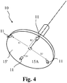
- the rotor 10 comprises a support plate 15' with discoid form substantially facing and coplanar with the ground (T), with substantially vertical rotation axis Z orthogonal to the lying plane of the plate 15', from whose lower face 15A the nozzles 11 project.
- the nozzles 11 can be mounted at different radial distances from the rotation axis Z, i.e. simultaneously or alternatively they can be mounted with different tilts.
- the nozzles are advantageously supplied by the rotating hydraulic joint 80 through tubes 81 arranged radially on the support plate 15'.
- the nozzles are advantageously arranged at different radial distances starting from over half the radius towards the peripheral edge, in order to cover a wider zone of treatment of the ground.
- nozzles 11 are assumed at the radial distances R1-R4, of which at least two are different from each other (in figure 4 , all are indicated as different from each other).
- Such plate 15' is advantageously made of plastic material and in particular with a Teflon disc with diameter comprised between 200 and 800 mm, in particular fixed with screws to the rotation shaft of the hydraulic motor 12.
- Teflon disc 15' preferably has the tubes 81 inserted in radial holes obtained in its thickness, which terminate at the radial position from which they must emit the pressurised water jets towards the ground.
- the rotor 10 is mounted on a bracket structure 100 for the support thereof, on which also the movement means 12 and the hydraulic joint 80 are advantageously arranged.
- bracket structure 100 is vertically hinged to the frame 3 connected to the tractor by means of a hinge 101, such that it can rotate with respect to a substantially vertical axis Z' between an interference position PI inside the rows and a non-interference position P2 outside the rows in the case of tree cultivations, or between an internal position and an external position with respect to the uprights of a guardrail or more generally to obstacles on the edge of a roadway, in the case of a road.
- the bracket structure 100 is forced by thrust means 102 to always return towards the position inside the rows or roadside obstacles, i.e. towards the position PI of interference with the plants of rows or with the roadside obstacles, during the advancing of the tractor along an advancement direction parallel to the rows or road.
- the interference position PI inside the rows or between the roadside obstacles represents the position of stability in which the bracket structure is arranged, in particular subjected to the action of its weight and of the different springs as specified hereinbelow.
- the bracket structure 100 can at least partly unload its weight by means of suspension means 103 preferably obtained with a first spring advantageously mounted between the frame 3 and the bracket structure 100.
- the thrust means 102 advantageously comprise at least first elastic means 104, simply obtained for example with a second spring, connected between the bracket structure 100 and the frame 3 and mounted along a connection direction A having a component A1 in the direction of the rows or towards the interference position PI inside the rows in order to carry the bracket structure 100 into such position, after it has sustained a thrust and moved away from such position following interference with the plant or with an obstacle on the side of the road during the advancing of the tractor.
- a support frame 105 is arranged around the rotor 10 and is directed so as to abut against the trunk of the plants or against a roadside obstacle during the advancing of the equipment 1, and consequently push the bracket structure 100 away, rotating it around its substantially vertical rotation axis Z' from the position inside the rows or obstacles to the position outside the rows or obstacles.
- Such support frame 105 is for example obtained with a metal ring supported by the bracket structure 100 at a few centimetres from the edge of the rotor 10.
- the bracket structure 100 comprises a support plate 106 beneath which the rotor 10 is mounted by means of the rotating hydraulic joint 80, from which an arm 107 is extended towards the frame 3; the free end of such arm 107 bears a bushing 108 adapted to obtain the jacket of the hinge 101 pin.
- Such bushing 108 has a tilted profile 108' that rests on a tilted support 3' of the frame 3, so as to be forced by its weight towards the position inside the rows.
- the bushing 108 can vertically slide along the hinge 101 pin and is opposed in its lifting by the abutment against the tilted surface 3' of the frame 3 by the action of a third spring 109 aimed to push the bushing 108 downward.
- the aforesaid third spring 109 is mounted coaxially with the pin and operates between an end stop nut 120 mounted on the pin and the aforesaid bushing 108.
- bracket structure 100 In case of vertical stresses transmitted from the frame 3 to the bracket structure 100, e.g. due to stones or rugged terrain, such bracket structure 100 can be lifted by sliding with the bushing 108 along the hinge 101 pin in order to follow the received stress.
- the thrust means 102 comprise, according to a preferred embodiment of the invention in addition to those already advantageously mentioned above, second elastic means 110, e.g. obtained with a fourth spring; also such elastic means 110 are connected between the bracket structure 100 and the frame 3 but they are mounted along a connection direction B having a component B1 in the direction towards the position outside the rows, having the purpose of preventing an excessively deep insertion of the rotor 10 between the plants or roadside obstacles when the rotor is moved beyond the position inside the rows into a position further away from the tractor 2 with the arm of the bracket 100 even more externally open.
- second elastic means 110 e.g. obtained with a fourth spring
- the bracket structure 100 is forced by the thrust means 102 to always return towards the interference position PI inside the rows or roadside obstacles, always being forced towards such position both after having intercepted a trunk or an obstacle and having been moved away therefrom (in this case by operating the first elastic means 104), and after having been excessively inserted between the rows or obstacles (in the latter case by operating the second elastic means 110).
- the bracket structure 100 preferably but not necessarily having at least partly unloaded its weight that lies on the hinge 101 due to the action of the first and/or second and/or fourth spring 103, 104, 110, oscillates with little friction between the two internal (or interference) positions and external (or non-interference) positions with respect to the rows, following the blows that it receives by striking with its support frame 105 against the trunks of the trees of the rows or against the roadside obstacles.
- the bracket structure 100 For the entire space that lies between each row or obstacle, the bracket structure 100 is situated in a stable position inside the rows, while each time that it abuts with the support frame 105 against the trunk of a tree of the row or against a roadside obstacle, it is moved towards the external non-interference position until there is no longer interference with the trunk of the plant or with the roadside obstacle and the bracket structure 100 can return into the interference position PI between the rows or between the roadside obstacles.
- the thrust means 102 are aimed to ensure that, in the shortest time possible, the rotor 10 returns to the interference position PI inside the rows.
- the thrust means 12 at least with second elastic means 104, the latter will be aimed to quickly bring the bracket 100 back towards the aforesaid internal position as soon as there is no more plant or obstacle presence.
- a protection casing 111 is mounted that is for example obtained with chains.
- Such protection casing 111 is adapted to prevent the sprays or even small stones from being ejected by said rotor 10 towards the machine or in any case towards zones outside the area in proximity to the rotor.
- the frame 3 of the equipment 1 is provided with a wheel 200 for resting on the ground T, which is adjustably mounted on an upright of the frame 3 in order to vary the height of the rotor 10 with respect to the ground.
- the plane of the plate 15' or the opening profile of the bell-shaped element 16 can define a lying plane ⁇ of the rotor 10 which is substantially coplanar with the ground, or which is advantageously tilted forward, i.e. in the advancing sense of the tractor 2, by an angle ⁇ smaller than 8 degrees in order to move part of the ground treated by the nozzles 11, during the advancing of the equipment 1, towards the rear part of the same rotor 10 which thus preferably remains slightly raised from the ground T.
- the same lying plane ⁇ of the rotor 10 can be tilted laterally with respect to the advancement direction Y of the rotor 10 parallel to the advancement direction Y of the tractor 2, by an angle ⁇ (not illustrated) in order to substantially face, in a coplanar manner, the mound of the row F of the tree cultivation, i.e. that mound of earth that is normally provided along the row F.
- the movement means 12 are susceptible of rotating the rotor 10 at a speed comprised between 300 and 1000 revolutions per minute in order to uniformly distribute the action of the jets 13 over the entire ground zone affected by the advancing of the rotor on the ground T, following the advancing of the tractor 2.
- the finding thus conceived therefore achieves the predefined objects.
Landscapes
- Life Sciences & Earth Sciences (AREA)
- Environmental Sciences (AREA)
- Engineering & Computer Science (AREA)
- Insects & Arthropods (AREA)
- Pest Control & Pesticides (AREA)
- Wood Science & Technology (AREA)
- Zoology (AREA)
- Soil Working Implements (AREA)
- Catching Or Destruction (AREA)
- Medicines Containing Plant Substances (AREA)
Applications Claiming Priority (1)
| Application Number | Priority Date | Filing Date | Title |
|---|---|---|---|
| IT000362A ITPD20130362A1 (it) | 2013-12-31 | 2013-12-31 | Apparecchiatura per la distruzione del cotico erboso, in particolare in filari di colture arboree. |
Publications (2)
| Publication Number | Publication Date |
|---|---|
| EP2888941A1 EP2888941A1 (en) | 2015-07-01 |
| EP2888941B1 true EP2888941B1 (en) | 2018-05-16 |
Family
ID=50190574
Family Applications (1)
| Application Number | Title | Priority Date | Filing Date |
|---|---|---|---|
| EP14199894.8A Active EP2888941B1 (en) | 2013-12-31 | 2014-12-22 | Equipment for destroying turf |
Country Status (4)
| Country | Link |
|---|---|
| EP (1) | EP2888941B1 (it) |
| ES (1) | ES2683088T3 (it) |
| IT (1) | ITPD20130362A1 (it) |
| PT (1) | PT2888941T (it) |
Families Citing this family (4)
| Publication number | Priority date | Publication date | Assignee | Title |
|---|---|---|---|---|
| ITUA20164020A1 (it) * | 2016-06-01 | 2017-12-01 | Antonio Farinazzo | Macchina decespugliatrice o taglia erba per bordo strada |
| ITUA20164575A1 (it) * | 2016-06-21 | 2017-12-21 | Giorgio Micheletti | Apparato per lo sfalcio di erba, erbacce o similari |
| ITUA20164822A1 (it) * | 2016-06-30 | 2017-12-30 | Erardo Mateo Mayer | Apparato per il diserbo di un'area mediante un fluido di lavoro ad alta pressione |
| DE102021201308A1 (de) | 2021-02-11 | 2022-08-11 | Hochschule für Wirtschaft und Umwelt Nürtingen-Geislingen (HfWU) Körperschaft des öffentlichen Rechts | Verfahren und Vorrichtung zur gezielten Abgabe eines Wirkmittels auf einen Boden |
Family Cites Families (9)
| Publication number | Priority date | Publication date | Assignee | Title |
|---|---|---|---|---|
| GB2093327A (en) | 1981-02-21 | 1982-09-02 | Watts Derek James | High pressure liquid cutting means |
| US5385106A (en) * | 1992-08-24 | 1995-01-31 | Langshaw; Eric | Hot water/steam weed killing system |
| DE29913887U1 (de) * | 1999-08-09 | 1999-12-02 | Merlaku, Kastriot, 84347 Pfarrkirchen | Mähdrescher |
| DE29919431U1 (de) | 1999-11-04 | 2001-03-15 | Gerhard Dücker GmbH & Co. KG Landmaschinenfabrik, 48703 Stadtlohn | Mähgerät |
| FR2887113B1 (fr) * | 2005-06-17 | 2009-01-16 | Gyrax Soc Par Actions Simplifi | Broyeur avec module de broyage lateral articule ne blessant pas les obstacles |
| US20070227418A1 (en) * | 2006-03-30 | 2007-10-04 | Polfer Jeffrey J | Apparatus for eliminating undesirable vegetation |
| US20090249758A1 (en) * | 2008-04-08 | 2009-10-08 | Darryll Duane Weeden | Sidewinder Fence Mower |
| WO2013006921A1 (en) * | 2011-07-13 | 2013-01-17 | South Australian No-Till Farmers Association Inc. | Weed pruner |
| GB201122263D0 (en) * | 2011-12-23 | 2012-02-01 | Weeding Technologies Ltd | Weed control |
-
2013
- 2013-12-31 IT IT000362A patent/ITPD20130362A1/it unknown
-
2014
- 2014-12-22 ES ES14199894.8T patent/ES2683088T3/es active Active
- 2014-12-22 PT PT141998948T patent/PT2888941T/pt unknown
- 2014-12-22 EP EP14199894.8A patent/EP2888941B1/en active Active
Non-Patent Citations (1)
| Title |
|---|
| None * |
Also Published As
| Publication number | Publication date |
|---|---|
| PT2888941T (pt) | 2018-07-24 |
| ES2683088T3 (es) | 2018-09-24 |
| ITPD20130362A1 (it) | 2015-07-01 |
| EP2888941A1 (en) | 2015-07-01 |
Similar Documents
| Publication | Publication Date | Title |
|---|---|---|
| US10375891B2 (en) | Agricultural device | |
| EP2888941A1 (en) | Equipment for destroying turf, in particular in cultivations of trees in rows | |
| AU2010226963B2 (en) | Method and apparatus for in situ treatment of grass | |
| AU2022228189B2 (en) | Recycle and drift reduction spray system for vineyards and tree crops | |
| US20130056561A1 (en) | Drip Irrigation System and Apparatus for Installation Thereof | |
| US5467723A (en) | Combined cultivator and fluid injector system | |
| HU209851B (en) | Cultivator | |
| EP3142472B1 (en) | An agricultural implement for removing the weeds that form in land used as orchards and vineyards | |
| GB2470669A (en) | A seeder for use with turf overseeding apparatus | |
| Larson | Revegetation equipment catalog | |
| CN206118923U (zh) | 农田表层土壤高温喷烧灭虫机 | |
| EP4054304B1 (en) | Weeding device | |
| CN212812638U (zh) | 多向旋抛玉米锄草机 | |
| WO2023179833A1 (ru) | Рабочий орган косилки-измельчителя (варианты) и косилка –измельчитель с его применением (варианты) | |
| US20160073594A1 (en) | System and Method for the Comminution and Harvesting of Trees and Brush Type Vegetation | |
| US20160044863A1 (en) | Low clearance row crop application system | |
| CN220875125U (zh) | 一种割草打药一体机 | |
| CN205962495U (zh) | 除草刀具及使用该除草刀具的果园除草装置 | |
| RU2369060C2 (ru) | Устройство роторного типа для прополки бахчевых культур в рядках | |
| CN217694242U (zh) | 一种农业种植用除草施肥装置 | |
| US5924495A (en) | Apparatus and method for removal of surface debris from crop rows | |
| RU2101926C1 (ru) | Устройство для срезания древесно-кустарниковой и стебельной растительности | |
| CN212588773U (zh) | 新型果林断根遁耕深施肥一体机 | |
| CN110622951B (zh) | 一种自识别园艺除草机 | |
| WO2019177560A1 (ru) | Устройство для обработки почвы и извлечения из нее сорных растений |
Legal Events
| Date | Code | Title | Description |
|---|---|---|---|
| PUAI | Public reference made under article 153(3) epc to a published international application that has entered the european phase |
Free format text: ORIGINAL CODE: 0009012 |
|
| 17P | Request for examination filed |
Effective date: 20141222 |
|
| AK | Designated contracting states |
Kind code of ref document: A1 Designated state(s): AL AT BE BG CH CY CZ DE DK EE ES FI FR GB GR HR HU IE IS IT LI LT LU LV MC MK MT NL NO PL PT RO RS SE SI SK SM TR |
|
| AX | Request for extension of the european patent |
Extension state: BA ME |
|
| R17P | Request for examination filed (corrected) |
Effective date: 20151229 |
|
| RBV | Designated contracting states (corrected) |
Designated state(s): AL AT BE BG CH CY CZ DE DK EE ES FI FR GB GR HR HU IE IS IT LI LT LU LV MC MK MT NL NO PL PT RO RS SE SI SK SM TR |
|
| GRAP | Despatch of communication of intention to grant a patent |
Free format text: ORIGINAL CODE: EPIDOSNIGR1 |
|
| INTG | Intention to grant announced |
Effective date: 20171218 |
|
| GRAS | Grant fee paid |
Free format text: ORIGINAL CODE: EPIDOSNIGR3 |
|
| GRAA | (expected) grant |
Free format text: ORIGINAL CODE: 0009210 |
|
| AK | Designated contracting states |
Kind code of ref document: B1 Designated state(s): AL AT BE BG CH CY CZ DE DK EE ES FI FR GB GR HR HU IE IS IT LI LT LU LV MC MK MT NL NO PL PT RO RS SE SI SK SM TR |
|
| REG | Reference to a national code |
Ref country code: GB Ref legal event code: FG4D |
|
| REG | Reference to a national code |
Ref country code: CH Ref legal event code: EP |
|
| REG | Reference to a national code |
Ref country code: IE Ref legal event code: FG4D |
|
| REG | Reference to a national code |
Ref country code: DE Ref legal event code: R096 Ref document number: 602014025486 Country of ref document: DE |
|
| REG | Reference to a national code |
Ref country code: AT Ref legal event code: REF Ref document number: 998708 Country of ref document: AT Kind code of ref document: T Effective date: 20180615 |
|
| REG | Reference to a national code |
Ref country code: PT Ref legal event code: SC4A Ref document number: 2888941 Country of ref document: PT Date of ref document: 20180724 Kind code of ref document: T Free format text: AVAILABILITY OF NATIONAL TRANSLATION Effective date: 20180716 |
|
| REG | Reference to a national code |
Ref country code: CH Ref legal event code: NV Representative=s name: KIRKER AND CIE S.A., CH Ref country code: NL Ref legal event code: FP |
|
| REG | Reference to a national code |
Ref country code: ES Ref legal event code: FG2A Ref document number: 2683088 Country of ref document: ES Kind code of ref document: T3 Effective date: 20180924 |
|
| REG | Reference to a national code |
Ref country code: LT Ref legal event code: MG4D |
|
| PG25 | Lapsed in a contracting state [announced via postgrant information from national office to epo] |
Ref country code: LT Free format text: LAPSE BECAUSE OF FAILURE TO SUBMIT A TRANSLATION OF THE DESCRIPTION OR TO PAY THE FEE WITHIN THE PRESCRIBED TIME-LIMIT Effective date: 20180516 Ref country code: SE Free format text: LAPSE BECAUSE OF FAILURE TO SUBMIT A TRANSLATION OF THE DESCRIPTION OR TO PAY THE FEE WITHIN THE PRESCRIBED TIME-LIMIT Effective date: 20180516 Ref country code: NO Free format text: LAPSE BECAUSE OF FAILURE TO SUBMIT A TRANSLATION OF THE DESCRIPTION OR TO PAY THE FEE WITHIN THE PRESCRIBED TIME-LIMIT Effective date: 20180816 Ref country code: FI Free format text: LAPSE BECAUSE OF FAILURE TO SUBMIT A TRANSLATION OF THE DESCRIPTION OR TO PAY THE FEE WITHIN THE PRESCRIBED TIME-LIMIT Effective date: 20180516 Ref country code: BG Free format text: LAPSE BECAUSE OF FAILURE TO SUBMIT A TRANSLATION OF THE DESCRIPTION OR TO PAY THE FEE WITHIN THE PRESCRIBED TIME-LIMIT Effective date: 20180816 |
|
| PG25 | Lapsed in a contracting state [announced via postgrant information from national office to epo] |
Ref country code: LV Free format text: LAPSE BECAUSE OF FAILURE TO SUBMIT A TRANSLATION OF THE DESCRIPTION OR TO PAY THE FEE WITHIN THE PRESCRIBED TIME-LIMIT Effective date: 20180516 Ref country code: RS Free format text: LAPSE BECAUSE OF FAILURE TO SUBMIT A TRANSLATION OF THE DESCRIPTION OR TO PAY THE FEE WITHIN THE PRESCRIBED TIME-LIMIT Effective date: 20180516 Ref country code: GR Free format text: LAPSE BECAUSE OF FAILURE TO SUBMIT A TRANSLATION OF THE DESCRIPTION OR TO PAY THE FEE WITHIN THE PRESCRIBED TIME-LIMIT Effective date: 20180817 Ref country code: HR Free format text: LAPSE BECAUSE OF FAILURE TO SUBMIT A TRANSLATION OF THE DESCRIPTION OR TO PAY THE FEE WITHIN THE PRESCRIBED TIME-LIMIT Effective date: 20180516 |
|
| PG25 | Lapsed in a contracting state [announced via postgrant information from national office to epo] |
Ref country code: DK Free format text: LAPSE BECAUSE OF FAILURE TO SUBMIT A TRANSLATION OF THE DESCRIPTION OR TO PAY THE FEE WITHIN THE PRESCRIBED TIME-LIMIT Effective date: 20180516 Ref country code: PL Free format text: LAPSE BECAUSE OF FAILURE TO SUBMIT A TRANSLATION OF THE DESCRIPTION OR TO PAY THE FEE WITHIN THE PRESCRIBED TIME-LIMIT Effective date: 20180516 Ref country code: SK Free format text: LAPSE BECAUSE OF FAILURE TO SUBMIT A TRANSLATION OF THE DESCRIPTION OR TO PAY THE FEE WITHIN THE PRESCRIBED TIME-LIMIT Effective date: 20180516 Ref country code: EE Free format text: LAPSE BECAUSE OF FAILURE TO SUBMIT A TRANSLATION OF THE DESCRIPTION OR TO PAY THE FEE WITHIN THE PRESCRIBED TIME-LIMIT Effective date: 20180516 Ref country code: CZ Free format text: LAPSE BECAUSE OF FAILURE TO SUBMIT A TRANSLATION OF THE DESCRIPTION OR TO PAY THE FEE WITHIN THE PRESCRIBED TIME-LIMIT Effective date: 20180516 Ref country code: RO Free format text: LAPSE BECAUSE OF FAILURE TO SUBMIT A TRANSLATION OF THE DESCRIPTION OR TO PAY THE FEE WITHIN THE PRESCRIBED TIME-LIMIT Effective date: 20180516 |
|
| REG | Reference to a national code |
Ref country code: DE Ref legal event code: R097 Ref document number: 602014025486 Country of ref document: DE |
|
| PG25 | Lapsed in a contracting state [announced via postgrant information from national office to epo] |
Ref country code: SM Free format text: LAPSE BECAUSE OF FAILURE TO SUBMIT A TRANSLATION OF THE DESCRIPTION OR TO PAY THE FEE WITHIN THE PRESCRIBED TIME-LIMIT Effective date: 20180516 |
|
| PLBE | No opposition filed within time limit |
Free format text: ORIGINAL CODE: 0009261 |
|
| STAA | Information on the status of an ep patent application or granted ep patent |
Free format text: STATUS: NO OPPOSITION FILED WITHIN TIME LIMIT |
|
| 26N | No opposition filed |
Effective date: 20190219 |
|
| PG25 | Lapsed in a contracting state [announced via postgrant information from national office to epo] |
Ref country code: SI Free format text: LAPSE BECAUSE OF FAILURE TO SUBMIT A TRANSLATION OF THE DESCRIPTION OR TO PAY THE FEE WITHIN THE PRESCRIBED TIME-LIMIT Effective date: 20180516 |
|
| GBPC | Gb: european patent ceased through non-payment of renewal fee |
Effective date: 20181222 |
|
| PG25 | Lapsed in a contracting state [announced via postgrant information from national office to epo] |
Ref country code: LU Free format text: LAPSE BECAUSE OF NON-PAYMENT OF DUE FEES Effective date: 20181222 Ref country code: MC Free format text: LAPSE BECAUSE OF FAILURE TO SUBMIT A TRANSLATION OF THE DESCRIPTION OR TO PAY THE FEE WITHIN THE PRESCRIBED TIME-LIMIT Effective date: 20180516 |
|
| REG | Reference to a national code |
Ref country code: IE Ref legal event code: MM4A |
|
| PG25 | Lapsed in a contracting state [announced via postgrant information from national office to epo] |
Ref country code: IE Free format text: LAPSE BECAUSE OF NON-PAYMENT OF DUE FEES Effective date: 20181222 |
|
| PG25 | Lapsed in a contracting state [announced via postgrant information from national office to epo] |
Ref country code: AL Free format text: LAPSE BECAUSE OF FAILURE TO SUBMIT A TRANSLATION OF THE DESCRIPTION OR TO PAY THE FEE WITHIN THE PRESCRIBED TIME-LIMIT Effective date: 20180516 |
|
| PG25 | Lapsed in a contracting state [announced via postgrant information from national office to epo] |
Ref country code: GB Free format text: LAPSE BECAUSE OF NON-PAYMENT OF DUE FEES Effective date: 20181222 |
|
| PG25 | Lapsed in a contracting state [announced via postgrant information from national office to epo] |
Ref country code: MT Free format text: LAPSE BECAUSE OF NON-PAYMENT OF DUE FEES Effective date: 20181222 |
|
| PG25 | Lapsed in a contracting state [announced via postgrant information from national office to epo] |
Ref country code: TR Free format text: LAPSE BECAUSE OF FAILURE TO SUBMIT A TRANSLATION OF THE DESCRIPTION OR TO PAY THE FEE WITHIN THE PRESCRIBED TIME-LIMIT Effective date: 20180516 |
|
| PG25 | Lapsed in a contracting state [announced via postgrant information from national office to epo] |
Ref country code: CY Free format text: LAPSE BECAUSE OF FAILURE TO SUBMIT A TRANSLATION OF THE DESCRIPTION OR TO PAY THE FEE WITHIN THE PRESCRIBED TIME-LIMIT Effective date: 20180516 Ref country code: MK Free format text: LAPSE BECAUSE OF NON-PAYMENT OF DUE FEES Effective date: 20180516 Ref country code: HU Free format text: LAPSE BECAUSE OF FAILURE TO SUBMIT A TRANSLATION OF THE DESCRIPTION OR TO PAY THE FEE WITHIN THE PRESCRIBED TIME-LIMIT; INVALID AB INITIO Effective date: 20141222 |
|
| PG25 | Lapsed in a contracting state [announced via postgrant information from national office to epo] |
Ref country code: IS Free format text: LAPSE BECAUSE OF FAILURE TO SUBMIT A TRANSLATION OF THE DESCRIPTION OR TO PAY THE FEE WITHIN THE PRESCRIBED TIME-LIMIT Effective date: 20180916 |
|
| REG | Reference to a national code |
Ref country code: AT Ref legal event code: UEP Ref document number: 998708 Country of ref document: AT Kind code of ref document: T Effective date: 20180516 |
|
| REG | Reference to a national code |
Ref country code: CH Ref legal event code: U11 Free format text: ST27 STATUS EVENT CODE: U-0-0-U10-U11 (AS PROVIDED BY THE NATIONAL OFFICE) Effective date: 20260101 |
|
| PGFP | Annual fee paid to national office [announced via postgrant information from national office to epo] |
Ref country code: DE Payment date: 20251211 Year of fee payment: 12 |
|
| PGFP | Annual fee paid to national office [announced via postgrant information from national office to epo] |
Ref country code: PT Payment date: 20251211 Year of fee payment: 12 Ref country code: AT Payment date: 20251222 Year of fee payment: 12 |
|
| PGFP | Annual fee paid to national office [announced via postgrant information from national office to epo] |
Ref country code: IT Payment date: 20251126 Year of fee payment: 12 |
|
| PGFP | Annual fee paid to national office [announced via postgrant information from national office to epo] |
Ref country code: FR Payment date: 20251223 Year of fee payment: 12 Ref country code: NL Payment date: 20251219 Year of fee payment: 12 |
|
| PGFP | Annual fee paid to national office [announced via postgrant information from national office to epo] |
Ref country code: BE Payment date: 20251219 Year of fee payment: 12 |
|
| PGFP | Annual fee paid to national office [announced via postgrant information from national office to epo] |
Ref country code: ES Payment date: 20260130 Year of fee payment: 12 |
|
| PGFP | Annual fee paid to national office [announced via postgrant information from national office to epo] |
Ref country code: CH Payment date: 20260101 Year of fee payment: 12 |