EP2889081A1 - Knetrotor und knetmaschine - Google Patents
Knetrotor und knetmaschine Download PDFInfo
- Publication number
- EP2889081A1 EP2889081A1 EP13831152.7A EP13831152A EP2889081A1 EP 2889081 A1 EP2889081 A1 EP 2889081A1 EP 13831152 A EP13831152 A EP 13831152A EP 2889081 A1 EP2889081 A1 EP 2889081A1
- Authority
- EP
- European Patent Office
- Prior art keywords
- kneading
- rotor
- kneading rotor
- convex portion
- shaft center
- Prior art date
- Legal status (The legal status is an assumption and is not a legal conclusion. Google has not performed a legal analysis and makes no representation as to the accuracy of the status listed.)
- Withdrawn
Links
- 238000004898 kneading Methods 0.000 title claims abstract description 206
- 239000000463 material Substances 0.000 claims abstract description 64
- 230000010006 flight Effects 0.000 claims abstract description 23
- 230000002093 peripheral effect Effects 0.000 claims description 4
- 238000011144 upstream manufacturing Methods 0.000 description 3
- 239000000654 additive Substances 0.000 description 2
- 230000000996 additive effect Effects 0.000 description 2
- 239000008188 pellet Substances 0.000 description 2
- 239000002952 polymeric resin Substances 0.000 description 2
- 239000000843 powder Substances 0.000 description 2
- 230000000452 restraining effect Effects 0.000 description 2
- 238000010008 shearing Methods 0.000 description 2
- 229920003002 synthetic resin Polymers 0.000 description 2
- 230000007423 decrease Effects 0.000 description 1
- 230000000694 effects Effects 0.000 description 1
- 238000012986 modification Methods 0.000 description 1
- 230000004048 modification Effects 0.000 description 1
- 239000011800 void material Substances 0.000 description 1
Images


Classifications
-
- B—PERFORMING OPERATIONS; TRANSPORTING
- B01—PHYSICAL OR CHEMICAL PROCESSES OR APPARATUS IN GENERAL
- B01F—MIXING, e.g. DISSOLVING, EMULSIFYING OR DISPERSING
- B01F27/00—Mixers with rotary stirring devices in fixed receptacles; Kneaders
- B01F27/05—Stirrers
- B01F27/07—Stirrers characterised by their mounting on the shaft
- B01F27/072—Stirrers characterised by their mounting on the shaft characterised by the disposition of the stirrers with respect to the rotating axis
- B01F27/0722—Stirrers characterised by their mounting on the shaft characterised by the disposition of the stirrers with respect to the rotating axis perpendicular with respect to the rotating axis
-
- B—PERFORMING OPERATIONS; TRANSPORTING
- B01—PHYSICAL OR CHEMICAL PROCESSES OR APPARATUS IN GENERAL
- B01F—MIXING, e.g. DISSOLVING, EMULSIFYING OR DISPERSING
- B01F27/00—Mixers with rotary stirring devices in fixed receptacles; Kneaders
- B01F27/60—Mixers with rotary stirring devices in fixed receptacles; Kneaders with stirrers rotating about a horizontal or inclined axis
- B01F27/72—Mixers with rotary stirring devices in fixed receptacles; Kneaders with stirrers rotating about a horizontal or inclined axis with helices or sections of helices
- B01F27/721—Mixers with rotary stirring devices in fixed receptacles; Kneaders with stirrers rotating about a horizontal or inclined axis with helices or sections of helices with two or more helices in the same receptacle
- B01F27/722—Mixers with rotary stirring devices in fixed receptacles; Kneaders with stirrers rotating about a horizontal or inclined axis with helices or sections of helices with two or more helices in the same receptacle the helices closely surrounded by a casing
-
- B—PERFORMING OPERATIONS; TRANSPORTING
- B29—WORKING OF PLASTICS; WORKING OF SUBSTANCES IN A PLASTIC STATE IN GENERAL
- B29B—PREPARATION OR PRETREATMENT OF THE MATERIAL TO BE SHAPED; MAKING GRANULES OR PREFORMS; RECOVERY OF PLASTICS OR OTHER CONSTITUENTS OF WASTE MATERIAL CONTAINING PLASTICS
- B29B7/00—Mixing; Kneading
- B29B7/30—Mixing; Kneading continuous, with mechanical mixing or kneading devices
- B29B7/34—Mixing; Kneading continuous, with mechanical mixing or kneading devices with movable mixing or kneading devices
- B29B7/38—Mixing; Kneading continuous, with mechanical mixing or kneading devices with movable mixing or kneading devices rotary
- B29B7/40—Mixing; Kneading continuous, with mechanical mixing or kneading devices with movable mixing or kneading devices rotary with single shaft
- B29B7/42—Mixing; Kneading continuous, with mechanical mixing or kneading devices with movable mixing or kneading devices rotary with single shaft with screw or helix
- B29B7/426—Mixing; Kneading continuous, with mechanical mixing or kneading devices with movable mixing or kneading devices rotary with single shaft with screw or helix with consecutive casings or screws, e.g. for charging, discharging, mixing
-
- B—PERFORMING OPERATIONS; TRANSPORTING
- B29—WORKING OF PLASTICS; WORKING OF SUBSTANCES IN A PLASTIC STATE IN GENERAL
- B29B—PREPARATION OR PRETREATMENT OF THE MATERIAL TO BE SHAPED; MAKING GRANULES OR PREFORMS; RECOVERY OF PLASTICS OR OTHER CONSTITUENTS OF WASTE MATERIAL CONTAINING PLASTICS
- B29B7/00—Mixing; Kneading
- B29B7/30—Mixing; Kneading continuous, with mechanical mixing or kneading devices
- B29B7/34—Mixing; Kneading continuous, with mechanical mixing or kneading devices with movable mixing or kneading devices
- B29B7/38—Mixing; Kneading continuous, with mechanical mixing or kneading devices with movable mixing or kneading devices rotary
- B29B7/46—Mixing; Kneading continuous, with mechanical mixing or kneading devices with movable mixing or kneading devices rotary with more than one shaft
- B29B7/465—Mixing; Kneading continuous, with mechanical mixing or kneading devices with movable mixing or kneading devices rotary with more than one shaft each shaft comprising rotor parts of the Banbury type in addition to screw parts
-
- B—PERFORMING OPERATIONS; TRANSPORTING
- B29—WORKING OF PLASTICS; WORKING OF SUBSTANCES IN A PLASTIC STATE IN GENERAL
- B29B—PREPARATION OR PRETREATMENT OF THE MATERIAL TO BE SHAPED; MAKING GRANULES OR PREFORMS; RECOVERY OF PLASTICS OR OTHER CONSTITUENTS OF WASTE MATERIAL CONTAINING PLASTICS
- B29B7/00—Mixing; Kneading
- B29B7/30—Mixing; Kneading continuous, with mechanical mixing or kneading devices
- B29B7/34—Mixing; Kneading continuous, with mechanical mixing or kneading devices with movable mixing or kneading devices
- B29B7/38—Mixing; Kneading continuous, with mechanical mixing or kneading devices with movable mixing or kneading devices rotary
- B29B7/46—Mixing; Kneading continuous, with mechanical mixing or kneading devices with movable mixing or kneading devices rotary with more than one shaft
- B29B7/48—Mixing; Kneading continuous, with mechanical mixing or kneading devices with movable mixing or kneading devices rotary with more than one shaft with intermeshing devices, e.g. screws
- B29B7/482—Mixing; Kneading continuous, with mechanical mixing or kneading devices with movable mixing or kneading devices rotary with more than one shaft with intermeshing devices, e.g. screws provided with screw parts in addition to other mixing parts, e.g. paddles, gears, discs
-
- B—PERFORMING OPERATIONS; TRANSPORTING
- B29—WORKING OF PLASTICS; WORKING OF SUBSTANCES IN A PLASTIC STATE IN GENERAL
- B29B—PREPARATION OR PRETREATMENT OF THE MATERIAL TO BE SHAPED; MAKING GRANULES OR PREFORMS; RECOVERY OF PLASTICS OR OTHER CONSTITUENTS OF WASTE MATERIAL CONTAINING PLASTICS
- B29B7/00—Mixing; Kneading
- B29B7/30—Mixing; Kneading continuous, with mechanical mixing or kneading devices
- B29B7/34—Mixing; Kneading continuous, with mechanical mixing or kneading devices with movable mixing or kneading devices
- B29B7/38—Mixing; Kneading continuous, with mechanical mixing or kneading devices with movable mixing or kneading devices rotary
- B29B7/46—Mixing; Kneading continuous, with mechanical mixing or kneading devices with movable mixing or kneading devices rotary with more than one shaft
- B29B7/48—Mixing; Kneading continuous, with mechanical mixing or kneading devices with movable mixing or kneading devices rotary with more than one shaft with intermeshing devices, e.g. screws
- B29B7/487—Mixing; Kneading continuous, with mechanical mixing or kneading devices with movable mixing or kneading devices rotary with more than one shaft with intermeshing devices, e.g. screws with consecutive casings or screws, e.g. for feeding, discharging, mixing
-
- B—PERFORMING OPERATIONS; TRANSPORTING
- B29—WORKING OF PLASTICS; WORKING OF SUBSTANCES IN A PLASTIC STATE IN GENERAL
- B29B—PREPARATION OR PRETREATMENT OF THE MATERIAL TO BE SHAPED; MAKING GRANULES OR PREFORMS; RECOVERY OF PLASTICS OR OTHER CONSTITUENTS OF WASTE MATERIAL CONTAINING PLASTICS
- B29B7/00—Mixing; Kneading
- B29B7/30—Mixing; Kneading continuous, with mechanical mixing or kneading devices
- B29B7/34—Mixing; Kneading continuous, with mechanical mixing or kneading devices with movable mixing or kneading devices
- B29B7/38—Mixing; Kneading continuous, with mechanical mixing or kneading devices with movable mixing or kneading devices rotary
- B29B7/46—Mixing; Kneading continuous, with mechanical mixing or kneading devices with movable mixing or kneading devices rotary with more than one shaft
- B29B7/48—Mixing; Kneading continuous, with mechanical mixing or kneading devices with movable mixing or kneading devices rotary with more than one shaft with intermeshing devices, e.g. screws
- B29B7/488—Parts, e.g. casings, sealings; Accessories, e.g. flow controlling or throttling devices
- B29B7/489—Screws
-
- B—PERFORMING OPERATIONS; TRANSPORTING
- B29—WORKING OF PLASTICS; WORKING OF SUBSTANCES IN A PLASTIC STATE IN GENERAL
- B29C—SHAPING OR JOINING OF PLASTICS; SHAPING OF MATERIAL IN A PLASTIC STATE, NOT OTHERWISE PROVIDED FOR; AFTER-TREATMENT OF THE SHAPED PRODUCTS, e.g. REPAIRING
- B29C48/00—Extrusion moulding, i.e. expressing the moulding material through a die or nozzle which imparts the desired form; Apparatus therefor
- B29C48/25—Component parts, details or accessories; Auxiliary operations
- B29C48/36—Means for plasticising or homogenising the moulding material or forcing it through the nozzle or die
- B29C48/50—Details of extruders
- B29C48/505—Screws
- B29C48/57—Screws provided with kneading disc-like elements, e.g. with oval-shaped elements
-
- B—PERFORMING OPERATIONS; TRANSPORTING
- B01—PHYSICAL OR CHEMICAL PROCESSES OR APPARATUS IN GENERAL
- B01F—MIXING, e.g. DISSOLVING, EMULSIFYING OR DISPERSING
- B01F2101/00—Mixing characterised by the nature of the mixed materials or by the application field
- B01F2101/2805—Mixing plastics, polymer material ingredients, monomers or oligomers
-
- B—PERFORMING OPERATIONS; TRANSPORTING
- B29—WORKING OF PLASTICS; WORKING OF SUBSTANCES IN A PLASTIC STATE IN GENERAL
- B29C—SHAPING OR JOINING OF PLASTICS; SHAPING OF MATERIAL IN A PLASTIC STATE, NOT OTHERWISE PROVIDED FOR; AFTER-TREATMENT OF THE SHAPED PRODUCTS, e.g. REPAIRING
- B29C48/00—Extrusion moulding, i.e. expressing the moulding material through a die or nozzle which imparts the desired form; Apparatus therefor
- B29C48/03—Extrusion moulding, i.e. expressing the moulding material through a die or nozzle which imparts the desired form; Apparatus therefor characterised by the shape of the extruded material at extrusion
-
- B—PERFORMING OPERATIONS; TRANSPORTING
- B29—WORKING OF PLASTICS; WORKING OF SUBSTANCES IN A PLASTIC STATE IN GENERAL
- B29C—SHAPING OR JOINING OF PLASTICS; SHAPING OF MATERIAL IN A PLASTIC STATE, NOT OTHERWISE PROVIDED FOR; AFTER-TREATMENT OF THE SHAPED PRODUCTS, e.g. REPAIRING
- B29C48/00—Extrusion moulding, i.e. expressing the moulding material through a die or nozzle which imparts the desired form; Apparatus therefor
- B29C48/25—Component parts, details or accessories; Auxiliary operations
- B29C48/268—Throttling of the flow, e.g. for cooperating with plasticising elements or for degassing
Definitions
- the present invention relates to a kneading rotor and a kneading machine capable of kneading a material while restraining a temperature rise of the material.
- a material such as a polymer resin pellet or a powder additive is supplied into a barrel, and a pair of kneading rotors inserted into the barrel are rotated to thereby knead the material within the barrel.
- kneading rotors each are provided, about their shaft centers, with a plurality of kneading flights for kneading the material.
- kneading rotors When each kneading rotor is rotated, the material within the barrel is tearingly separated from each other.
- the kneading rotor in the kneading machine is thus generally provided with the kneading flights that each have a cross-section suitable for shearing the material.
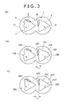
- Fig. 4 of Patent Document 1 discloses a kneading rotor having kneading flights suitable for shearing the material. Note that, for easy understanding, a kneading rotor having substantially the same shape as a kneading rotor shown in Fig. 4 of Patent Document 1 is illustrated as prior art 1 in Fig. 2 (b) of the present description.
- the kneading rotor in Patent Document 1 has three kneading flights about the horizontally oriented shaft center, each of which kneading flights has a triangular cross-section that projects radially outwardly.
- the projecting end of this kneading flight is a portion referred to as a tip portion and located in the neighborhood of an inner circumferential surface of the barrel.
- the operating mechanism is that a narrow clearance is provided between the tip portion and the inner circumferential surface of the barrel, so that the material is introduced into this clearance to thereby apply a shear force to the material.
- the kneading flight has a slanted face so as to be continuously connected with the side of the tip portion.
- the slanted faces those that face the material when the kneading rotor rotates are working faces.
- Patent Document 1 JP H06-41135 (Refer to Fig. 4 )
- the working face is in a radially outwardly convex shape, as shown in an ovally encircled area in the figure.
- This convex working face is not greatly slanted relative to the inner wall surface of the barrel, and the distance from the surface of the kneading flight to the inner wall surface of the barrel is comparatively short.
- the present invention is made in light of the above described problems, and its object is to provide a kneading rotor and a kneading machine capable of positively restraining a temperature rise of a material and localized variations in temperature within the material.
- a kneading rotor is rotatably disposed about a horizontally oriented shaft center, the kneading rotor including at least two or more of kneading flights that are disposed about the shaft center and knead a material, characterized in that in a cross-section perpendicular with the shaft center of the kneading rotor, the kneading flights each have a working face that faces the material when the kneading rotor is rotated, and that a recess resulting from the working face being partially recessed radially inwardly is formed on the working face of each kneading flight.
- a convex portion resulting from a surface of the kneading flight partially projecting radially outwardly may be formed between circumferentially adjacent kneading flights, and a place between a tip portion of the kneading flight and the top of the convex portion may be made to be the recess.
- an outer peripheral surface of the convex portion may be formed into a cylindrical surface having the shaft center of the kneading rotor as the center line.
- the convex portion is formed such that the diameter from the shaft center of the kneading rotor to the top of the convex portion may be 0.6 times or more the diameter from the shaft center of the kneading rotor to the tip portion of the kneading flight.
- a temperature rise of a material and localized variations in temperature within the material can positively be restrained.
- Embodiments of a kneading rotor 1 according to the present invention and a kneading machine 2 provided with this kneading rotor 1 will be described hereinafter in detail with reference to the drawings.
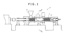
- Fig. 1 shows the kneading machine 2 provided with the kneading rotor 1 according to a first embodiment (the kneading machine 2 according to the first embodiment).
- the kneading machine 2 is the one that kneads a material such as a polymer resin pellet or a powder additive, and includes the knead rotor 1 that kneads the material.
- the kneading machine 2 according to the present invention is described by exemplifying a double shaft continuous kneading machine of different direction rotation type which includes a double shaft of the kneading rotors 1 that each rotate in different directions.
- a double shaft continuous kneading machine of different direction rotation type a double shaft continuous kneading machine of the same direction rotation type, a double shaft extruder, or a batch type kneading machine can also be used as the kneading machine 2 according to the present invention.
- the kneading machine 2 includes a barrel 3 having a void in its interior, and a pair of the left and right kneading rotors 1, 1 that are housed within the barrel 3.
- the two circular through-holes 4 each capable of housing the kneading rotor 1 are perforated as being aligned in parallel rows. Inner wall surfaces of the two circular through-holes 4, 4 are configured or designed to partially overlap each other, enabling the material to be moved from one circular through-hole 4 to another.
- These two circular through-holes 4, 4 each have one kneading rotor 1 inserted therein.
- the kneading machine 2 is of double shaft type that has in total two shafts of the kneading rotor 1.
- the left-hand side of Fig. 1 is referred to as a location upstream of the machine and the right-hand side thereof is referred to as a location downstream of the machine.
- the left and right lateral direction in Fig. 1 is referred to as an axial direction and moreover, the direction perpendicular relative to the axial direction is referred to as an axis perpendicular direction.
- the direction far from the shaft center is referred to as radially outward portion
- the direction closer to the shaft center is referred to as radially inward portion.
- the barrel 3 is formed into a long cylindrical shape in the horizontal direction.
- the two circular through-holes 4, 4 are formed as being aligned in parallel rows into the barrel 3 so as to be oriented from the location upstream of the machine to the location downstream thereof (in the axial direction).
- a hopper 5 Disposed in an intermediate location in the axial direction of the barrel 3 is a hopper 5 through which a material is supplied into the barrel 3.
- the circular through-holes 4 are substantially cylindrical lateral holes formed by hollowing out the barrel 3 in the horizontal direction, and its cross-section in the axis perpendicular direction is made to be substantially circular.
- a pair of the left and right circular through-holes 4 are aligned in parallel in the horizontal direction, and formed into a so-called "eyeglass shape" such that their inner walls are partially jointed together.
- the kneading rotor 1 is the one that kneads a material supplied into the barrel 3, and formed into an elongated shape in the axial direction.
- the pair of left and right kneading rotors 1 is provided, so that each rotor is configured to be inserted into the pair of the circular through-holes 4 as described above.
- the kneading rotor 1 on the left-hand side rotates clockwise and the kneading rotor 1 on the right-hand side rotates counter-clockwise, as viewed from the location upstream of the machine.
- the kneading rotor 1 is formed by axially combining various types of segments, and a plurality of rotor segments 6 (segments for kneading) is provided in an intermediate portion in the axial direction.
- the rotor segments 6 are the ones suitable for in particular kneading among various types of segments.
- the rotor segments 6 are each formed into a distorted triangle in cross-section in the axis perpendicular direction, and includes three kneading flights 7 having radially outwardly projecting peak ends about the shaft center. These kneading flights 7 each have at their projecting peak ends a tip potion 8 that faces the inner wall surface of the barrel 3.
- the tip portion 8 of each of the kneading flights 7 rotates so as to pass the closer portion of the inner wall surface of the barrel 3, so that the material attached to the inner wall surface of the barrel 3 can be scraped without leaving anything behind to knead the material.
- each kneading flight 7 of the above described kneading rotor 1 is provided with a slanted working face 9 that faces the material when the kneading rotor 1 rotates.
- the working face 9 is formed so as to be circumferentially continuous relative to the tip portion 8 of the kneading flight 7, and for the kneading rotor 1 on the left-hand sides of Fig. 2 (a) to Fig. 2 (c) the working face is adjacently provided clockwise (rotation direction) as viewed from the tip portion 8.
- This working face 9 can be of various shapes and have a slanted angle, as shown in Fig. 2 (a) to Fig. 2 (c) .
- a working face 109 is formed in an ovally encircled area in the figure, as a slanted face relative to an inner wall surface of a circular through-hole 104 of a barrel.
- This working face 109 of the prior art 1 is formed into a curved convex bulging out radially outwardly (outer peripheral side), and does not include a very large slanted angle relative to the inner wall surface of the circular through-holes 104 of the barrel.
- the working face 109 has a slanted angle that conforms to the inner wall surface of the circular through-hole 104 of the barrel.
- the working face 109 protrudes toward the inner wall surface (radially outwardly) of the circular through-hole 104 of the barrel, and the distance is accordingly reduced between the working face 109 and the inner wall surface of the circular through-holes 104 of the barrel.
- a working face 209 is formed, in an ovally encircled area in the figure, as a slanted face relative to an inner wall surface of a circular through-hole 204 of a barrel.
- the difference between the working face 209 of the prior art 2 and that of the prior art 1 is that the working face 209 of the prior art 2 is formed into a planar face that connects by the minimum length between two tip portions 208 of the circumferentially adjacent kneading flights 207.
- the working face 209 of the prior art 2 does not bulge out radially outwardly, and includes a very large slanted angle relative to the inner wall surface of the circular through-holes 204 of the barrel.
- the working face 209 has a large slanted angle and accordingly, the number of places where the distance between the inner wall surface of the circular through-hole 204 of the barrel and the surfaces of the kneading flights 207 is reduced decreases than that of the prior art 1.
- the shear force applied to the material becomes smaller than that of the prior art 1.
- a rotor clearance L2 formed between the left and right lateral kneading rotors 201 becomes greater as compared to a rotor clearance L1 formed between the left and right lateral kneading rotors 101 of the prior art 1.
- the shear force applied to the material varies greatly, resulting in increased localized variations of the temperature within the material.
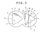
- the working face 9 of the kneading flight 7 is formed with a recess 10 formed by the working face 9 being partially recessed radially inwardly. If such a recess 10 is formed on the working face 9, the inner wall surface of the circular through-hole 4 of the barrel 3 is accordingly spaced apart from the surface of the kneading flight 7 and the shear force applied to the material is thereby reduced, which allows the rise of the material temperature to be restrained.
- the surface of the kneading flight 7, other than the place where the recess 10 is formed, can also be caused to project radially outwardly, the rotor clearance formed between the left-right lateral kneading rotors 1 can be reduced, enabling the restraint of localized variations in temperature within the material.
- the kneading rotor 1 is formed with a convex portion 11 that results from the surface of the kneading flight 7 partially projecting radially outwardly, between the circumferentially adjacent kneading flights 7, 7, in a cross-section perpendicular to the shaft center of the kneading rotor 1. And a place between a top 11' of this convex potion 11 and the tip portion 8 of the kneading flight 7 becomes recessed, contrary to the convex potion 11, by providing this convex portion 11, which place is the above described recess 10.
- the working face 9, as shown in the ovally encircled area in Fig. 3 is a face that is slanted so as to face the material when the kneading rotor 1 rotates, and is formed at a circumferentially continuous position relative to the tip portion 8 (adjacent position).
- This working face 9 is formed so as to be slanted circumferentially, so that when the kneading rotor 1 rotates, the material within the barrel 3 makes contact with the working face 9.
- the convex portion 11 is the one formed by the surface of the kneading flight 7 being caused to partially project radially outwardly, as described above, and an outer peripheral surface thereof is formed into a cylindrical surface having the shaft center of the kneading rotor 1 as the center line. That is, in the cross-section perpendicular to the shaft center of the kneading rotor 1, the convex potion 11 is in a shape of a circular arc having the shaft center of the kneading rotor 1 as its center of curvature, and is bulged out so as to project radially outwardly from a straight line that connects between the circumferentially adjacent tip portions 8.
- the recess 10 is a resultingly formed portion by the above described convex portion 11 being formed.
- the recess 10 is configured or designed to be recessed radially inwardly than a reference line S (shown in straight dash-dot lines in the figure) that connects between the tip portion 8 of the kneading flight 7 and the top 11' (peak) of the above described convex portion 11.
- the convex portion 11 is preferably formed such that a radius from the shaft center of the kneading rotor 1 to the top 11' of the convex potion 11 may be 0.6 or more times a radius from the shaft center of the kneading rotor 1 to the tip portion 8 of the kneading flight 7.
- the amount of projection of the convex portion 11, in other words, the radius from the shaft center of the kneading rotor 1 to the top 11' of the convex portion 11 will be described next.
- the inside diameter of the barrel 3, i.e., the diameter of the inner wall surface of the barrel 3 circular through-hole 4 is assumed to be db.
- the maximum outside diameter of the kneading rotor 1, i.e., two times the distance from the shaft center of the kneading rotor 1 to the tip portion 8 (the top of the flight) is assumed to be dr.
- three types of the kneading rotors 1, as shown in Figs 4 (a) to 4 (c) are considered such that the ratio of db and dr (dr/db) is 0.85.
- Figs. 6 (a) and (b) show results obtained by measuring how the temperature of a material rises per revolution when kneading rotors of prior arts 1 and 2, and the kneading rotor 1 of the present embodiment are rotated a single revolution. Further, Figs. 7 (a) and (b) each show results obtained by measuring variations of the material temperatures within the barrel 3, as the standard variations of measured temperatures. Note that Fig 6 (a) and Fig. 7 (a) each show the results for when the ratio (dr/db) is 0.85, and Fig 6 (b) and Fig. 7 (b) each show the results for when the ratio (dr/db) is 0.98.
- the temperature rise in the prior art 2 is in the range of slightly above 0.5 degrees C, whereas in the prior art 1, as ds/dr becomes from 0.55 to 0.6 to 0.72, each temperature rise increases by 0.6 to 0.7 degrees C. As compared to this, even if ds/dr increases from 0.55 to 0.6 to 0.72, the temperature rise in the present embodiment is 0.5 to 0.6 degrees C, which rate remains small, and does not increase as high as that of the prior art 1. Note that ds in the prior art 1 represents the radius of a circle inscribed in the visible outline of the kneading rotor 14.
- the temperature variations of the material of the prior art 2 exceeds 0.11 degrees, whereas as ds/dr increases from 0.55 to 0.6 to 0.72, each variation of the prior art 1 is reduced to 0.09 degrees C to 0.10 degrees C.
- the temperature variation in the present embodiment when ds/dr is 0.55, is 0.11 degrees C, which is great; however, when ds/dr is 0.6 or 0.72, the temperature variation is 0.085 degrees C to 0.10 degrees C, and is smaller than that of the prior art 1.
- the use of the kneading rotor 1 according to the first embodiment allows for positive restraint of a temperature rise of the material and localized variations in temperature within the material.
- the kneading rotor 1 according to the second embodiment and the kneading machine 2 provided with this kneading rotor 1 will next be described.
- Fig. 8 shows a cross-sectional view of the kneading rotor according to the second embodiment.
- the working face 9 in a cross-section perpendicular to the shaft center of the kneading rotor 1, unlike the simple recessed working face 9 as in the first embodiment includes the working face 9 is formed to have complex irregularities so that the cross-section of the working face 9 is wavy.
- a first convex portion 11a which is provided closer to the tip portion 8
- a second convex portion 11b which is provided farther from the tip portion 8 are provided.
- the portion between the first convex portion 11a and the second convex portion 11b is made to be the recess 10.
- the working face 9 of the kneading flight 7 according to the second embodiment is curved in the neighborhood of the tip portion 8 so as to bulge out radially outwardly relative to a reference line P (dash-dot lines in the figure) connecting between the circumferentially adjacent tip portions.
- This portion which curved toward radially outwardly is the first convex portion 11a.
- the second convex portion 11b is formed which projects radially outwardly more greatly than the first convex portion 11a.
- a portion gently recessed radially inwardly between the first convex portion 11a and the second convex portion 11b, is made to be the recess 10.
Landscapes
- Engineering & Computer Science (AREA)
- Mechanical Engineering (AREA)
- Chemical & Material Sciences (AREA)
- Chemical Kinetics & Catalysis (AREA)
- Processing And Handling Of Plastics And Other Materials For Molding In General (AREA)
- Mixers Of The Rotary Stirring Type (AREA)
Applications Claiming Priority (2)
| Application Number | Priority Date | Filing Date | Title |
|---|---|---|---|
| JP2012182676A JP5822800B2 (ja) | 2012-08-21 | 2012-08-21 | 混練ロータ及び混練機 |
| PCT/JP2013/072017 WO2014030598A1 (ja) | 2012-08-21 | 2013-08-16 | 混練ロータ及び混練機 |
Publications (2)
| Publication Number | Publication Date |
|---|---|
| EP2889081A1 true EP2889081A1 (de) | 2015-07-01 |
| EP2889081A4 EP2889081A4 (de) | 2016-04-13 |
Family
ID=50149907
Family Applications (1)
| Application Number | Title | Priority Date | Filing Date |
|---|---|---|---|
| EP13831152.7A Withdrawn EP2889081A4 (de) | 2012-08-21 | 2013-08-16 | Knetrotor und knetmaschine |
Country Status (6)
| Country | Link |
|---|---|
| US (1) | US20150182926A1 (de) |
| EP (1) | EP2889081A4 (de) |
| JP (1) | JP5822800B2 (de) |
| KR (1) | KR101704311B1 (de) |
| CN (1) | CN104507558B (de) |
| WO (1) | WO2014030598A1 (de) |
Families Citing this family (6)
| Publication number | Priority date | Publication date | Assignee | Title |
|---|---|---|---|---|
| JP6430902B2 (ja) * | 2015-07-06 | 2018-11-28 | 日本スピンドル製造株式会社 | 密閉式混練機 |
| JP6361607B2 (ja) * | 2015-08-28 | 2018-07-25 | トヨタ自動車株式会社 | 混練機およびそれを用いる電極活物質を含む電極体の製造方法 |
| CN106393471A (zh) * | 2016-11-16 | 2017-02-15 | 哈尔滨理工大学 | 新型混炼式转矩流变仪转子 |
| JP7002343B2 (ja) * | 2017-01-26 | 2022-01-20 | 株式会社神戸製鋼所 | ゴム混練機の排出口を開閉するドア |
| US20210187452A1 (en) * | 2018-08-30 | 2021-06-24 | Kyocera Corporation | Rotating member, kneading machine member, and kneading machine using same, bearing and bearing unit using same |
| EP4556195A1 (de) * | 2023-11-14 | 2025-05-21 | Steer Engineering Private Limited | Element für eine gegendrehende doppelschneckenbearbeitungsvorrichtung |
Family Cites Families (25)
| Publication number | Priority date | Publication date | Assignee | Title |
|---|---|---|---|---|
| US3184790A (en) * | 1962-09-15 | 1965-05-25 | Toyo Tire & Rubber Co | Screw for the cold feed extruder of the compounded rubber |
| US3403894A (en) * | 1967-08-03 | 1968-10-01 | Stewart Bolling & Co Inc | Rotor and mixer |
| SE426561B (sv) * | 1975-05-29 | 1983-01-31 | Usm Corp | Genommatande blandare |
| JPS59147629A (ja) * | 1983-02-12 | 1984-08-24 | Masao Moriyama | 連続混練装置 |
| KR910005193B1 (ko) * | 1982-12-30 | 1991-07-23 | 모리야마 마사오 | 혼련장치 (混練裝置) |
| US4474475A (en) * | 1982-12-30 | 1984-10-02 | Masao Moriyama | Mixing apparatus |
| JPS59123520A (ja) * | 1982-12-30 | 1984-07-17 | Masao Moriyama | 連続混練装置 |
| US4556324A (en) * | 1984-05-01 | 1985-12-03 | E. I. Du Pont De Nemours And Company | Apparatus for forming films of constant thickness |
| DE3519349A1 (de) * | 1985-05-30 | 1986-12-04 | IKA-Maschinenbau Janke & Kunkel GmbH & Co KG, 7812 Bad Krozingen | Knetmaschine |
| JPH0641135B2 (ja) * | 1989-04-04 | 1994-06-01 | 株式会社神戸製鋼所 | 連続混練機の混練制御装置 |
| JPH0677680B2 (ja) * | 1991-08-16 | 1994-10-05 | ビーエイチ工業有限会社 | 連続捏和機 |
| JP3254525B2 (ja) * | 1991-09-13 | 2002-02-12 | 大日本インキ化学工業株式会社 | 静電荷像現像用トナーの製造方法 |
| JPH0641135A (ja) | 1992-07-21 | 1994-02-15 | Nippon Soda Co Ltd | イミダゾプテリジン誘導体及びその製造方法 |
| JP2905418B2 (ja) * | 1994-04-18 | 1999-06-14 | 株式会社神戸製鋼所 | 混練機 |
| KR100199639B1 (ko) * | 1995-04-24 | 1999-06-15 | 토요다 히로시 | 밀폐형혼련장치 |
| JP2601645B2 (ja) * | 1995-06-06 | 1997-04-16 | 株式会社神戸製鋼所 | 連続混練機の混練制御装置 |
| DE19617606A1 (de) * | 1996-05-02 | 1997-11-06 | Wacker Chemie Gmbh | Kontinuierliches Verfahren zur Herstellung lagerstabiler Organopolysiloxanzusammensetzungen |
| JP3499414B2 (ja) * | 1996-12-24 | 2004-02-23 | 株式会社神戸製鋼所 | 2軸混練機 |
| JP3530334B2 (ja) * | 1997-03-06 | 2004-05-24 | 株式会社神戸製鋼所 | 連続混練機及び連続混練機のロータ |
| US6136246A (en) * | 1997-11-07 | 2000-10-24 | Rauwendaal Extrusion Engineering | Screw extruder with improved dispersive mixing elements |
| JP3574618B2 (ja) * | 2000-10-17 | 2004-10-06 | Nok株式会社 | 密閉式混練機 |
| JP4236963B2 (ja) * | 2003-03-12 | 2009-03-11 | 株式会社神戸製鋼所 | 密閉式混練機 |
| JP3854298B1 (ja) * | 2005-07-11 | 2006-12-06 | 株式会社神戸製鋼所 | 噛合型2軸押出機の混練度調整装置 |
| JP4568785B2 (ja) * | 2009-01-19 | 2010-10-27 | 株式会社神戸製鋼所 | 混練ロータ |
| JP5832172B2 (ja) * | 2010-08-05 | 2015-12-16 | 株式会社神戸製鋼所 | 連続混練装置 |
-
2012
- 2012-08-21 JP JP2012182676A patent/JP5822800B2/ja active Active
-
2013
- 2013-08-16 KR KR1020157003522A patent/KR101704311B1/ko active Active
- 2013-08-16 US US14/418,311 patent/US20150182926A1/en not_active Abandoned
- 2013-08-16 EP EP13831152.7A patent/EP2889081A4/de not_active Withdrawn
- 2013-08-16 CN CN201380040614.6A patent/CN104507558B/zh active Active
- 2013-08-16 WO PCT/JP2013/072017 patent/WO2014030598A1/ja not_active Ceased
Also Published As
| Publication number | Publication date |
|---|---|
| CN104507558B (zh) | 2017-03-08 |
| US20150182926A1 (en) | 2015-07-02 |
| CN104507558A (zh) | 2015-04-08 |
| KR20150036509A (ko) | 2015-04-07 |
| JP2014039899A (ja) | 2014-03-06 |
| KR101704311B1 (ko) | 2017-02-07 |
| JP5822800B2 (ja) | 2015-11-24 |
| EP2889081A4 (de) | 2016-04-13 |
| WO2014030598A1 (ja) | 2014-02-27 |
Similar Documents
| Publication | Publication Date | Title |
|---|---|---|
| US20150182926A1 (en) | Kneading rotor and kneading machine | |
| EP2792462B1 (de) | Dispersive Knetmethode | |
| JP5832172B2 (ja) | 連続混練装置 | |
| JP5137613B2 (ja) | ニーディングディスクセグメント及び2軸押出機 | |
| WO2009096450A1 (ja) | 混練度調整装置、押出機、及び連続混練機 | |
| CN106079135B (zh) | 一种同步六棱锯齿型动态变间隙密炼机转子 | |
| EP4470747A1 (de) | Element und schnecke für eine gegenläufige doppelschneckenbearbeitungsvorrichtung | |
| JP4834653B2 (ja) | 混練スクリュ及び押出機 | |
| KR100199639B1 (ko) | 밀폐형혼련장치 | |
| EP1005969A1 (de) | Rotor für Elastomermischer mit veränderlichem Gewindegang | |
| US10744551B2 (en) | Rolling-swaging tool and method for closing opening of cylindrical member using same | |
| JP5679874B2 (ja) | 2軸押出機 | |
| JP5631263B2 (ja) | 連続混練機 | |
| EP3284576A1 (de) | Getriebevorrichtung zur verwendung in einem mehrwellenextruder oder kneter | |
| US20150298078A1 (en) | Kneading device | |
| JP2016028799A (ja) | 混練撹拌装置 | |
| EP3106278B1 (de) | Kontinuierliche knetvorrichtung | |
| EP3409945A1 (de) | Flügelzellenpumpe und verfahren zur bestimmung des profils in inneren eines nockenrings davon | |
| JP5361704B2 (ja) | 混練用セグメント及び混練設備 | |
| EP3434359B1 (de) | Staubblockiervorrichtung für abgedichteten kneter | |
| JP2016028798A (ja) | 混練撹拌装置 | |
| JP2014043794A (ja) | インナーロータの製造方法及びそのインナーロータ | |
| JP2016028797A (ja) | 混練撹拌装置 |
Legal Events
| Date | Code | Title | Description |
|---|---|---|---|
| PUAI | Public reference made under article 153(3) epc to a published international application that has entered the european phase |
Free format text: ORIGINAL CODE: 0009012 |
|
| 17P | Request for examination filed |
Effective date: 20141215 |
|
| AK | Designated contracting states |
Kind code of ref document: A1 Designated state(s): AL AT BE BG CH CY CZ DE DK EE ES FI FR GB GR HR HU IE IS IT LI LT LU LV MC MK MT NL NO PL PT RO RS SE SI SK SM TR |
|
| AX | Request for extension of the european patent |
Extension state: BA ME |
|
| DAX | Request for extension of the european patent (deleted) | ||
| RA4 | Supplementary search report drawn up and despatched (corrected) |
Effective date: 20160316 |
|
| RIC1 | Information provided on ipc code assigned before grant |
Ipc: B29C 47/60 20060101ALI20160310BHEP Ipc: B29B 7/46 20060101AFI20160310BHEP Ipc: B29B 7/48 20060101ALI20160310BHEP |
|
| 17Q | First examination report despatched |
Effective date: 20170704 |
|
| STAA | Information on the status of an ep patent application or granted ep patent |
Free format text: STATUS: THE APPLICATION IS DEEMED TO BE WITHDRAWN |
|
| 18D | Application deemed to be withdrawn |
Effective date: 20190515 |