EP2889215A1 - Empennage horizontal d'un aéronef - Google Patents
Empennage horizontal d'un aéronef Download PDFInfo
- Publication number
- EP2889215A1 EP2889215A1 EP13382564.6A EP13382564A EP2889215A1 EP 2889215 A1 EP2889215 A1 EP 2889215A1 EP 13382564 A EP13382564 A EP 13382564A EP 2889215 A1 EP2889215 A1 EP 2889215A1
- Authority
- EP
- European Patent Office
- Prior art keywords
- spar
- horizontal tail
- tail plane
- ribs
- rib
- Prior art date
- Legal status (The legal status is an assumption and is not a legal conclusion. Google has not performed a legal analysis and makes no representation as to the accuracy of the status listed.)
- Withdrawn
Links
- 238000005304 joining Methods 0.000 description 5
- 238000005452 bending Methods 0.000 description 4
- 238000009826 distribution Methods 0.000 description 4
- 238000004519 manufacturing process Methods 0.000 description 3
- 230000007704 transition Effects 0.000 description 2
- OKTJSMMVPCPJKN-UHFFFAOYSA-N Carbon Chemical compound [C] OKTJSMMVPCPJKN-UHFFFAOYSA-N 0.000 description 1
- 229920002430 Fibre-reinforced plastic Polymers 0.000 description 1
- AYFVYJQAPQTCCC-GBXIJSLDSA-N L-threonine Chemical compound C[C@@H](O)[C@H](N)C(O)=O AYFVYJQAPQTCCC-GBXIJSLDSA-N 0.000 description 1
- 229910052799 carbon Inorganic materials 0.000 description 1
- 238000005516 engineering process Methods 0.000 description 1
- 239000011151 fibre-reinforced plastic Substances 0.000 description 1
- 239000000463 material Substances 0.000 description 1
- 238000000034 method Methods 0.000 description 1
- 238000005457 optimization Methods 0.000 description 1
- 238000004513 sizing Methods 0.000 description 1
- 239000003351 stiffener Substances 0.000 description 1
Images
Classifications
-
- B—PERFORMING OPERATIONS; TRANSPORTING
- B64—AIRCRAFT; AVIATION; COSMONAUTICS
- B64C—AEROPLANES; HELICOPTERS
- B64C5/00—Stabilising surfaces
- B64C5/02—Tailplanes
-
- B—PERFORMING OPERATIONS; TRANSPORTING
- B64—AIRCRAFT; AVIATION; COSMONAUTICS
- B64C—AEROPLANES; HELICOPTERS
- B64C3/00—Wings
- B64C3/18—Spars; Ribs; Stringers
Definitions
- the present invention refers to an optimized layout of structural elements, specifically covers, ribs, spars and stringers in a torsion box of a trimmable horizontal tail plane.
- HTP horizontal tail planes
- Known horizontal tail planes comprise right and left torsion boxes, both structures being joined by means of a central torsion box or by means of a central joint.
- Said torsion boxes comprise external and internal elements.
- the external elements of each torsion box are front spar and rear spars, two closing ribs and upper and lower covers.
- the known internal elements of each torsion box are:
- Pure multirib torsion box structures comprise a forward spar, a rear spar, ribs and upper and lower covers and pure multispar torsion box structures comprise a forward spar, a rear spar, intermediate spars, upper and lower covers and also ribs located next to the load introduction areas.
- the aim of the invention is to achieve weight savings and manufacturing improvements with respect to conventional multirib or multispar right and left torsion box concepts.
- the claimed horizontal tail plane provides advantages in terms of manufacturing and weight saving over the state of the art.
- the horizontal tail plane object of the invention comprises a single torsion box which comprises a front and rear spars, upper and lower covers and two closing ribs, the front spar, the rear spar and the upper and lower covers extending between said two closing ribs and along the whole span of the horizontal tail plane in a symmetric layout with respect to the symmetry axis or longitudinal axis of the aircraft.
- said single torsion box comprises elements, ie, front and rear spars and upper and lower covers extending between the two closing ribs.
- the element extends along the whole span of the HTP although said element could be split into several subelements for manufacturing purpose that are afterwards joined together in a continuous manner.
- the horizontal tail plane does not comprise an intermediate central box or an intermediate joint located in the central part for joining a right and a left torsion boxes.
- the resulting engineered structure is neither a pure multirib or a multispar architecture as it combines both philosophies.
- Another novelty of the invention is that the spars are not purely straight as they are kinked next to the central zone of the HTP.
- Upper and lower covers can be a one piece element or can be split into two upper and two lower covers.
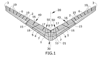
- Figure 1 shows an embodiment of the invention.
- the external or boundary elements are the following:
- the first intermediante spar (5) extends between the closing ribs (3) in a symmetric layout with respect to the symmetry axis (20) of the aircraft.
- the spars (1, 2, 4, 5) comprises straight portions having different orientations distributed in a symmetric layout with respect to the symmetry axis (20) of the aircraft.
- the changes of orientation between said portions of the spars (1, 2, 4, 5) are performed at their crossing with a rib (7, 8, 9, 10).
- the embodiment of the horizontal tail plane shown in Figure 1 also has the following three supporting points, as known in conventional horizontal tail planes:
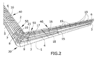
- the embodiment shown in Figures 1 and 2 comprises ribs extending from the supporting points (50, 30) and the actuators interface (40). Ribs of the embodiments shown in Figures 1 and 2 can be full-chord ribs which are ribs which join both front (1) and rear (2) spars or non-full-chord ribs which are ribs which extend from the front (1) or the rear (2) spar to an intermediate spar (4, 5).
- the front spar (1) and the intermediate spars (4, 5) shown in Figures 1 and 2 comprise at least a central portion perpendicular to the symmetry axis (20) of the aircraft and two lateral portions symmetric with respect to said symmetry axis (20) and forming an obtuse angle with the central portion.
- the horizontal tail plane of the embodiment also comprises stringers (6) which are spanwise distributed elements placed on the upper and lower covers and which extend between the two closing ribs (3) along the whole span of the horizontal tail plane. Therefore, the stringers (6) extend between the closing ribs (3) and along the whole span of the horizontal tail plane in a symmetric layout with respect to the symmetry axis (20) the aircraft.
- It also comprises two intermediate ribs (15) extending between the rear (2) and the front (1) spars at both sides of the symmetry axis (20) of the aircraft and located at a distance of 50 ⁇ 10% of the length of half the span measured along the rear spar plane from the symmetry axis (20) of the aircraft of the horizontal tail plane.
- the claimed layout is the result of an optimization which takes into account the most relevant sizing load cases, maximum and minimum vertical bending, maximum and minimum torsion and maximum asymmetric vertical bending.
- the elements forming the torsion box structure are arranged such that follow, as closely as possible, the predominant load paths also having a manufacturable structure.
- the resulting engineered structure which could be manufactured with today's technologies using known carbon fibre reinforced plastic materials and processes, provides a significant weight saving.
- the central zone is delimited by the two intermediate full-chord ribs or pivot ribs (7) extending from the pivot supporting points (50) which are significantly loaded areas. More specifically the angle of the pivot ribs (7) with respect to the rear spar (2) may vary between 90o and the resulting value of the angle of the rear spar (2) with respect to the symmetry axis (20) of the aircraft, ie, the pivot rib (7) parallel to said axis.
- This central zone there are three ribs (8, 9, 10). Two of the ribs called intermediate center ribs (8, 9) are placed next to the pivot ribs (7). The three ribs (8, 9, 10) are placed between the two pivot ribs (7). Intermediate center ribs (8, 9) improve the load transition between the rear spar (2) zone and horizontal tail plane jack fitting supporting point (30).
- the third rib is the center rib (10).
- the center rib (10) is an non-full-chord intermediate rib which extends between the rear spar (2) and the additional intermediate central spar (4) along the symmetry axis (20) of the aircraft.
- the intermediate spars (4, 5) are kinked looking for a proper load transition between central and lateral zones of the horizontal tail plane.
- the central portion of the intermediate spar (5) located close to the rear spar (2) extends between both pivot ribs (7).
- Said central portion of said intermediate spar (5) is located at a distance measured from the rear spar (2) between 15% and 30% of the distance between the rear spar (2) and the front spar (1).
- the first kink between the central portion and the lateral parts of the intermediate spar (4) located closer to the front spar (1) is performed at its crossing with the pivot ribs (7) and a second kink is performed at its crossing with the center ribs (8, 9).
- Said central portion of said intermediate spar (4) is located at a distance measured from the rear spar (2) between 60% and 75% of the distance between the rear spar (2) and the front spar (1).
- the central zone also comprises stiffeners (21) located spanwise and extending between the two pivot ribs (7).
- the stifferners (21) comprises a kink at their crossing with the center ribs (8, 9).
- Each lateral zone extends from the corresponding pivot rib (7) to the corresponding closing rib (3).
- the additional intermediate spar (4) extends between the two intermediate ribs (15) along the whole span of the horizontal tail plane and is located between the intermediate spar (5) and the front spar (1).
- the angle between the lateral portions of the intermediate spars (4, 5) and the rear spar (2) is between 0o and 10o.
- Both intermediate spars (4, 5) increase the horizontal tail plane bending inertia and prevent covers' buckling modes affecting entire bays.
- the first rib described is the actuator rib (16), which is an intermediate non-full-chord rib which connects the rear spar (2) at the actuator interface (40) with the intermediate spar (5).
- the angle of this element with respect to the rear spar (2) varies between 80o and 100o.
- this oblique rib (18) may vary between 60o ⁇ 10o and it is located between the actuator rib (16) and the additional intermediate rib (17) and extending between the front spar (1) and the rear spar (2).
- Stringers (6) are also spanwise distributed elements extending between the closing ribs (3) and along the whole span of the horizontal tail plane.
- Stringer layout (6) is conical between continuous spars, which means that stringers (6) located between two spars have a conical configuration with respect to those spars. This configuration determines an optimal bending stiffness depending on the load distribution.
Landscapes
- Engineering & Computer Science (AREA)
- Aviation & Aerospace Engineering (AREA)
- Mechanical Engineering (AREA)
- Moulding By Coating Moulds (AREA)
- Vibration Dampers (AREA)
Priority Applications (3)
| Application Number | Priority Date | Filing Date | Title |
|---|---|---|---|
| EP13382564.6A EP2889215A1 (fr) | 2013-12-27 | 2013-12-27 | Empennage horizontal d'un aéronef |
| US14/584,480 US20150183508A1 (en) | 2013-12-27 | 2014-12-29 | Horizontal tail plane of an aircraft |
| CN201410838482.8A CN104743097A (zh) | 2013-12-27 | 2014-12-29 | 飞行器的水平尾翼 |
Applications Claiming Priority (1)
| Application Number | Priority Date | Filing Date | Title |
|---|---|---|---|
| EP13382564.6A EP2889215A1 (fr) | 2013-12-27 | 2013-12-27 | Empennage horizontal d'un aéronef |
Publications (1)
| Publication Number | Publication Date |
|---|---|
| EP2889215A1 true EP2889215A1 (fr) | 2015-07-01 |
Family
ID=49998035
Family Applications (1)
| Application Number | Title | Priority Date | Filing Date |
|---|---|---|---|
| EP13382564.6A Withdrawn EP2889215A1 (fr) | 2013-12-27 | 2013-12-27 | Empennage horizontal d'un aéronef |
Country Status (3)
| Country | Link |
|---|---|
| US (1) | US20150183508A1 (fr) |
| EP (1) | EP2889215A1 (fr) |
| CN (1) | CN104743097A (fr) |
Families Citing this family (2)
| Publication number | Priority date | Publication date | Assignee | Title |
|---|---|---|---|---|
| CN105620789A (zh) * | 2016-02-23 | 2016-06-01 | 哈尔滨飞机工业集团有限责任公司 | 一种水平尾翼延长盒段 |
| GB2640446A (en) * | 2024-04-19 | 2025-10-22 | Fortescue Future Ind Pty Ltd | An aircraft |
Citations (5)
| Publication number | Priority date | Publication date | Assignee | Title |
|---|---|---|---|---|
| DE603773C (de) * | 1931-10-14 | 1934-10-08 | Provencale De Const Aeronautiq | Flugzeugtragfluegel |
| US3910531A (en) * | 1972-10-17 | 1975-10-07 | Aerospatiale | Shell-type structure for light aircraft |
| US4667905A (en) * | 1983-09-29 | 1987-05-26 | The Boeing Company | High strength to weight horizontal and vertical aircraft stabilizer |
| US20050236524A1 (en) * | 2004-04-27 | 2005-10-27 | The Boeing Company | Airfoil box and associated method |
| US20080265093A1 (en) * | 2007-04-30 | 2008-10-30 | Airbus Espana, S.L. | Integrated multispar torsion box of composite material |
Family Cites Families (8)
| Publication number | Priority date | Publication date | Assignee | Title |
|---|---|---|---|---|
| US3109614A (en) * | 1961-10-23 | 1963-11-05 | Boeing Co | Fin-tip mounted horizontal control surface for airplanes |
| US3417946A (en) * | 1967-12-29 | 1968-12-24 | Lockheed Aircraft Corp | T-tail construction for aircraft |
| US4034939A (en) * | 1975-11-05 | 1977-07-12 | The Boeing Company | Assembly for sealing the mounting opening for a flying horizontal stabilizer on a vertical stabilizer |
| US6190484B1 (en) * | 1999-02-19 | 2001-02-20 | Kari Appa | Monolithic composite wing manufacturing process |
| DE502005001475D1 (de) * | 2004-12-22 | 2007-10-25 | Airbus Deutschland Gmbh Hrb 43527 | Tragwerk einer aerodynamischen Wirkfläche eines Flugzeugs |
| US8074926B2 (en) * | 2006-12-22 | 2011-12-13 | Calvin Burgess | Structural dynamic stability for an aircraft |
| ES2346834B1 (es) * | 2007-04-30 | 2011-08-17 | Airbus Operations, S.L. | Estructura de costilla para cajones de torsion de un ala o de un estabilizador de una aeronave. |
| ES2330180B1 (es) * | 2007-06-28 | 2010-09-14 | Airbus España S.L. | Cajon de torsion multilarguero rigidizado. |
-
2013
- 2013-12-27 EP EP13382564.6A patent/EP2889215A1/fr not_active Withdrawn
-
2014
- 2014-12-29 US US14/584,480 patent/US20150183508A1/en not_active Abandoned
- 2014-12-29 CN CN201410838482.8A patent/CN104743097A/zh active Pending
Patent Citations (5)
| Publication number | Priority date | Publication date | Assignee | Title |
|---|---|---|---|---|
| DE603773C (de) * | 1931-10-14 | 1934-10-08 | Provencale De Const Aeronautiq | Flugzeugtragfluegel |
| US3910531A (en) * | 1972-10-17 | 1975-10-07 | Aerospatiale | Shell-type structure for light aircraft |
| US4667905A (en) * | 1983-09-29 | 1987-05-26 | The Boeing Company | High strength to weight horizontal and vertical aircraft stabilizer |
| US20050236524A1 (en) * | 2004-04-27 | 2005-10-27 | The Boeing Company | Airfoil box and associated method |
| US20080265093A1 (en) * | 2007-04-30 | 2008-10-30 | Airbus Espana, S.L. | Integrated multispar torsion box of composite material |
Also Published As
| Publication number | Publication date |
|---|---|
| CN104743097A (zh) | 2015-07-01 |
| US20150183508A1 (en) | 2015-07-02 |
Similar Documents
| Publication | Publication Date | Title |
|---|---|---|
| CA2649125C (fr) | Joint aile-fuselage composite | |
| CN102307782B (zh) | 在飞行器的后端中的负载引导区域的结构 | |
| EP2848519B1 (fr) | Joints supérieurs entre caisson d'aile extérieure et sections d'aile centrale d'un d'ensemble d'aile d'aéronef | |
| KR20140048256A (ko) | 윙의 윙팁 장치 및 이러한 윙팁 장치를 갖는 윙 | |
| US7810758B2 (en) | Arrangement for coupling a coupling pivot for a trimmable horizontal stabiliser to the tail fuselage of an aircraft | |
| CN103180207A (zh) | 复合材料构造体、具备该复合材料构造体的航空器主翼及航空器机身 | |
| CN204279981U (zh) | 一种用于火箭舱体的外环框 | |
| CN103429492B (zh) | 用非平行的纵梁强化的抗扭箱外壳 | |
| CA2804094A1 (fr) | Structure interne d'aeronef en materiau composite | |
| KR20100106623A (ko) | 항공기용 동체 구조체 | |
| EP3551305A1 (fr) | Rail à armature pour montagnes russes et agencement de montagnes russes | |
| EP2889215A1 (fr) | Empennage horizontal d'un aéronef | |
| EP3090940B1 (fr) | Plan horizontal d'empennage avec un caisson de torsion multi-nervure | |
| CN106482589B (zh) | 一种桁条壳体 | |
| EP3025954A1 (fr) | Cadre de fuselage d'aéronef | |
| CN104724280B (zh) | 飞行器控制表面 | |
| US9010688B2 (en) | Structural joint having continuous skin with inside and outside stringers | |
| CN105722757B (zh) | 在pi结合结构中的低应力加强件过渡段 | |
| CN112319775A (zh) | 用于飞机的t型尾部接头组件 | |
| EP3998192B1 (fr) | Structure de longeron d'aile | |
| US20170320561A1 (en) | Aircraft empennage | |
| US20260070652A1 (en) | Aircraft wing structure | |
| CN111319750B (zh) | 支撑翼飞行器 |
Legal Events
| Date | Code | Title | Description |
|---|---|---|---|
| PUAI | Public reference made under article 153(3) epc to a published international application that has entered the european phase |
Free format text: ORIGINAL CODE: 0009012 |
|
| 17P | Request for examination filed |
Effective date: 20131227 |
|
| AK | Designated contracting states |
Kind code of ref document: A1 Designated state(s): AL AT BE BG CH CY CZ DE DK EE ES FI FR GB GR HR HU IE IS IT LI LT LU LV MC MK MT NL NO PL PT RO RS SE SI SK SM TR |
|
| AX | Request for extension of the european patent |
Extension state: BA ME |
|
| R17P | Request for examination filed (corrected) |
Effective date: 20151228 |
|
| RBV | Designated contracting states (corrected) |
Designated state(s): AL AT BE BG CH CY CZ DE DK EE ES FI FR GB GR HR HU IE IS IT LI LT LU LV MC MK MT NL NO PL PT RO RS SE SI SK SM TR |
|
| STAA | Information on the status of an ep patent application or granted ep patent |
Free format text: STATUS: THE APPLICATION IS DEEMED TO BE WITHDRAWN |
|
| 18D | Application deemed to be withdrawn |
Effective date: 20170701 |