EP2889557B1 - Klimaanlage - Google Patents
Klimaanlage Download PDFInfo
- Publication number
- EP2889557B1 EP2889557B1 EP14190205.6A EP14190205A EP2889557B1 EP 2889557 B1 EP2889557 B1 EP 2889557B1 EP 14190205 A EP14190205 A EP 14190205A EP 2889557 B1 EP2889557 B1 EP 2889557B1
- Authority
- EP
- European Patent Office
- Prior art keywords
- heat
- exchanger
- refrigerant
- accumulator
- indoor
- Prior art date
- Legal status (The legal status is an assumption and is not a legal conclusion. Google has not performed a legal analysis and makes no representation as to the accuracy of the status listed.)
- Active
Links
Images




Classifications
-
- F—MECHANICAL ENGINEERING; LIGHTING; HEATING; WEAPONS; BLASTING
- F25—REFRIGERATION OR COOLING; COMBINED HEATING AND REFRIGERATION SYSTEMS; HEAT PUMP SYSTEMS; MANUFACTURE OR STORAGE OF ICE; LIQUEFACTION SOLIDIFICATION OF GASES
- F25B—REFRIGERATION MACHINES, PLANTS OR SYSTEMS; COMBINED HEATING AND REFRIGERATION SYSTEMS; HEAT PUMP SYSTEMS
- F25B30/00—Heat pumps
- F25B30/02—Heat pumps of the compression type
-
- F—MECHANICAL ENGINEERING; LIGHTING; HEATING; WEAPONS; BLASTING
- F25—REFRIGERATION OR COOLING; COMBINED HEATING AND REFRIGERATION SYSTEMS; HEAT PUMP SYSTEMS; MANUFACTURE OR STORAGE OF ICE; LIQUEFACTION SOLIDIFICATION OF GASES
- F25B—REFRIGERATION MACHINES, PLANTS OR SYSTEMS; COMBINED HEATING AND REFRIGERATION SYSTEMS; HEAT PUMP SYSTEMS
- F25B30/00—Heat pumps
- F25B30/06—Heat pumps characterised by the source of low potential heat
-
- F—MECHANICAL ENGINEERING; LIGHTING; HEATING; WEAPONS; BLASTING
- F25—REFRIGERATION OR COOLING; COMBINED HEATING AND REFRIGERATION SYSTEMS; HEAT PUMP SYSTEMS; MANUFACTURE OR STORAGE OF ICE; LIQUEFACTION SOLIDIFICATION OF GASES
- F25B—REFRIGERATION MACHINES, PLANTS OR SYSTEMS; COMBINED HEATING AND REFRIGERATION SYSTEMS; HEAT PUMP SYSTEMS
- F25B13/00—Compression machines, plants or systems, with reversible cycle
-
- F—MECHANICAL ENGINEERING; LIGHTING; HEATING; WEAPONS; BLASTING
- F24—HEATING; RANGES; VENTILATING
- F24F—AIR-CONDITIONING; AIR-HUMIDIFICATION; VENTILATION; USE OF AIR CURRENTS FOR SCREENING
- F24F5/00—Air-conditioning systems or apparatus not covered by F24F1/00 or F24F3/00, e.g. using solar heat or combined with household units such as an oven or water heater
- F24F5/0007—Air-conditioning systems or apparatus not covered by F24F1/00 or F24F3/00, e.g. using solar heat or combined with household units such as an oven or water heater cooling apparatus specially adapted for use in air-conditioning
- F24F5/001—Compression cycle type
-
- F—MECHANICAL ENGINEERING; LIGHTING; HEATING; WEAPONS; BLASTING
- F25—REFRIGERATION OR COOLING; COMBINED HEATING AND REFRIGERATION SYSTEMS; HEAT PUMP SYSTEMS; MANUFACTURE OR STORAGE OF ICE; LIQUEFACTION SOLIDIFICATION OF GASES
- F25B—REFRIGERATION MACHINES, PLANTS OR SYSTEMS; COMBINED HEATING AND REFRIGERATION SYSTEMS; HEAT PUMP SYSTEMS
- F25B27/00—Machines, plants or systems, using particular sources of energy
-
- F—MECHANICAL ENGINEERING; LIGHTING; HEATING; WEAPONS; BLASTING
- F25—REFRIGERATION OR COOLING; COMBINED HEATING AND REFRIGERATION SYSTEMS; HEAT PUMP SYSTEMS; MANUFACTURE OR STORAGE OF ICE; LIQUEFACTION SOLIDIFICATION OF GASES
- F25B—REFRIGERATION MACHINES, PLANTS OR SYSTEMS; COMBINED HEATING AND REFRIGERATION SYSTEMS; HEAT PUMP SYSTEMS
- F25B40/00—Subcoolers, desuperheaters or superheaters
-
- F—MECHANICAL ENGINEERING; LIGHTING; HEATING; WEAPONS; BLASTING
- F25—REFRIGERATION OR COOLING; COMBINED HEATING AND REFRIGERATION SYSTEMS; HEAT PUMP SYSTEMS; MANUFACTURE OR STORAGE OF ICE; LIQUEFACTION SOLIDIFICATION OF GASES
- F25B—REFRIGERATION MACHINES, PLANTS OR SYSTEMS; COMBINED HEATING AND REFRIGERATION SYSTEMS; HEAT PUMP SYSTEMS
- F25B40/00—Subcoolers, desuperheaters or superheaters
- F25B40/02—Subcoolers
-
- F—MECHANICAL ENGINEERING; LIGHTING; HEATING; WEAPONS; BLASTING
- F25—REFRIGERATION OR COOLING; COMBINED HEATING AND REFRIGERATION SYSTEMS; HEAT PUMP SYSTEMS; MANUFACTURE OR STORAGE OF ICE; LIQUEFACTION SOLIDIFICATION OF GASES
- F25B—REFRIGERATION MACHINES, PLANTS OR SYSTEMS; COMBINED HEATING AND REFRIGERATION SYSTEMS; HEAT PUMP SYSTEMS
- F25B41/00—Fluid-circulation arrangements
-
- F—MECHANICAL ENGINEERING; LIGHTING; HEATING; WEAPONS; BLASTING
- F25—REFRIGERATION OR COOLING; COMBINED HEATING AND REFRIGERATION SYSTEMS; HEAT PUMP SYSTEMS; MANUFACTURE OR STORAGE OF ICE; LIQUEFACTION SOLIDIFICATION OF GASES
- F25B—REFRIGERATION MACHINES, PLANTS OR SYSTEMS; COMBINED HEATING AND REFRIGERATION SYSTEMS; HEAT PUMP SYSTEMS
- F25B43/00—Arrangements for separating or purifying gases or liquids; Arrangements for vaporising the residuum of liquid refrigerant, e.g. by heat
-
- F—MECHANICAL ENGINEERING; LIGHTING; HEATING; WEAPONS; BLASTING
- F25—REFRIGERATION OR COOLING; COMBINED HEATING AND REFRIGERATION SYSTEMS; HEAT PUMP SYSTEMS; MANUFACTURE OR STORAGE OF ICE; LIQUEFACTION SOLIDIFICATION OF GASES
- F25B—REFRIGERATION MACHINES, PLANTS OR SYSTEMS; COMBINED HEATING AND REFRIGERATION SYSTEMS; HEAT PUMP SYSTEMS
- F25B43/00—Arrangements for separating or purifying gases or liquids; Arrangements for vaporising the residuum of liquid refrigerant, e.g. by heat
- F25B43/006—Accumulators
-
- F—MECHANICAL ENGINEERING; LIGHTING; HEATING; WEAPONS; BLASTING
- F25—REFRIGERATION OR COOLING; COMBINED HEATING AND REFRIGERATION SYSTEMS; HEAT PUMP SYSTEMS; MANUFACTURE OR STORAGE OF ICE; LIQUEFACTION SOLIDIFICATION OF GASES
- F25B—REFRIGERATION MACHINES, PLANTS OR SYSTEMS; COMBINED HEATING AND REFRIGERATION SYSTEMS; HEAT PUMP SYSTEMS
- F25B2400/00—Component parts or details not otherwise provided for in this subclass
- F25B2400/05—Compression system with heat exchange between particular parts of the system
- F25B2400/051—Compression system with heat exchange between particular parts of the system between the accumulator and another part of the cycle
-
- F—MECHANICAL ENGINEERING; LIGHTING; HEATING; WEAPONS; BLASTING
- F25—REFRIGERATION OR COOLING; COMBINED HEATING AND REFRIGERATION SYSTEMS; HEAT PUMP SYSTEMS; MANUFACTURE OR STORAGE OF ICE; LIQUEFACTION SOLIDIFICATION OF GASES
- F25B—REFRIGERATION MACHINES, PLANTS OR SYSTEMS; COMBINED HEATING AND REFRIGERATION SYSTEMS; HEAT PUMP SYSTEMS
- F25B2400/00—Component parts or details not otherwise provided for in this subclass
- F25B2400/13—Economisers
-
- F—MECHANICAL ENGINEERING; LIGHTING; HEATING; WEAPONS; BLASTING
- F25—REFRIGERATION OR COOLING; COMBINED HEATING AND REFRIGERATION SYSTEMS; HEAT PUMP SYSTEMS; MANUFACTURE OR STORAGE OF ICE; LIQUEFACTION SOLIDIFICATION OF GASES
- F25B—REFRIGERATION MACHINES, PLANTS OR SYSTEMS; COMBINED HEATING AND REFRIGERATION SYSTEMS; HEAT PUMP SYSTEMS
- F25B2400/00—Component parts or details not otherwise provided for in this subclass
- F25B2400/23—Separators
-
- F—MECHANICAL ENGINEERING; LIGHTING; HEATING; WEAPONS; BLASTING
- F25—REFRIGERATION OR COOLING; COMBINED HEATING AND REFRIGERATION SYSTEMS; HEAT PUMP SYSTEMS; MANUFACTURE OR STORAGE OF ICE; LIQUEFACTION SOLIDIFICATION OF GASES
- F25B—REFRIGERATION MACHINES, PLANTS OR SYSTEMS; COMBINED HEATING AND REFRIGERATION SYSTEMS; HEAT PUMP SYSTEMS
- F25B2400/00—Component parts or details not otherwise provided for in this subclass
- F25B2400/24—Thermal storage element
Definitions
- the present invention relates to an air conditioner, and more particularly, to an air conditioner that can improve the efficiency by overcooling a refrigerant using cold and heat of an accumulator during a cooling operation.
- an air conditioner is a system that keeps indoor air cool and warm using a refrigeration cycle including a compressor, an outdoor heat-exchanger, an expansion valve, and an indoor heat-exchanger. That is, the air conditioner may include a cooling device for keeping indoor air cool and a heating device for keeping indoor air warm. Also, the air conditioner may be designed to have both cooling and heating functions.
- the air conditioner is configured to include a four-way valve for converting a flow passage of a refrigerant compressed by a compressor in accordance with operational conditions (i.e., a cooling operation and a heating operation). That is, during the cooling operation, the refrigerant compressed in the compressor flows to the outdoor heat-exchanger through the four-way valve, and the outdoor heat-exchanger functions as a condenser. The refrigerant condensed by the outdoor heat-exchanger expands in the expansion valve, and then flows into the indoor heat-exchanger. In this case, the indoor heat-exchanger functions as a vaporizer. The refrigerant vaporized by the indoor heat-exchanger is redirected into the compressor through the four-way valve.
- operational conditions i.e., a cooling operation and a heating operation
- Document JP H08 5185 A discloses an air conditioner according to the preamble of claim 1.
- an object of the present invention is to provide an air conditioner that can improve the efficiency by overcooling a refrigerant using cold and heat of an accumulator during a cooling operation.
- an air conditioner having the features of claim 1.
- the accumulator jacket may comprise a flow passage allowing the refrigerating fluid to flow along the surface of the accumulator.
- the air conditioner according to the invention as claimed in claim 1, comprises a circulating pump that forcibly circulates the refrigerating fluid flowing in the supercooling heat-exchange hub and the accumulator jacket wherein the circulating pump may operate during the cooling operation, and does not operate during the heating operation
- the overcooling heat-exchange hub may overcool the refrigerant flowing from the outdoor heat-exchanger to the indoor heat-exchanger during the cooling operation.
- the air conditioner possibly further comprise an injection module disposed between the outdoor heat-exchanger and the indoor heat-exchanger and injecting a portion of the refrigerant flowing between the outdoor heat-exchanger and the indoor heat-exchanger to the compressor.
- the injection module may comprises, an injection expansion valve for expanding a portion of the refrigerant flowing between the indoor heat-exchanger and the outdoor heat-exchanger, and an injection heat-exchanger for exchanging heat between the other portion of the refrigerant flowing between the indoor heat-exchanger and the outdoor heat-exchanger and the refrigerant expanding in the injection expansion valve.
- the injection valve may be opened during the heating operation, and be closed during the cooling operation.
- FIG. 1 is a view illustrating a refrigerant cycle circuit of an air conditioner according to an embodiment of the present invention.
- FIG. 2 is a view illustrating a portion of an outdoor device of an air conditioner according to an embodiment of the present invention.
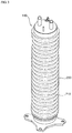
- FIG. 3 is a view illustrating an accumulator jacket installed on an accumulator of an air conditioner according to an embodiment of the present invention
- an air conditioner may include a compressor 110 for compressing a refrigerant, an outdoor heat-exchanger 120 that is disposed outside a room to heat-exchange between outdoor air and the refrigerant, an indoor heat-exchanger 130 that is disposed inside the room to heat-exchange between indoor air and the refrigerant, a converting valve 180 for guiding the refrigerant discharged from the compressor 110 to the outdoor heat-exchanger 120 during an cooling operation and guiding the refrigerant to the indoor heat-exchanger 130 during a heating operation, an accumulator 140 disposed between the compressor 110 and the converting valve 180 to separate the refrigerant into a liquid-phase refrigerant and a gas-phase refrigerant, an accumulator jacket 200 disposed on the surface of the accumulator 140 and containing a refrigerating fluid absorbing cold and heat generated in the accumulator 140 therein, a supercooling heat-exchange hub 190 connected
- the air conditioner may include an outdoor device disposed outside a room and an indoor device disposed inside the room, and the outdoor device and the indoor device may be connected to each other.
- the outdoor device may include a compressor 110, an outdoor heat-exchanger 120, an outdoor expansion valve 150, an injection module 170, an accumulator 140, a supercooling heat-exchange hub 190, a circulating pump 191, and an accumulator jacket 200.
- the indoor device may include an indoor heat-exchanger 130 and an indoor expansion valve 160.
- the compressor 110 may disposed in the outdoor device, and may compress a refrigerant introduced at a low-pressure and low-temperature state to a refrigerant of a high-pressure and high-temperature state.
- the compressor 110 may be formed in a variety of structures. That is, the compressor 110 may be a reciprocating compressor using a cylinder and a piston, a scroll compressor using an orbiting scroll and a fixed scroll, or an inverter compressor that controls the compression amount of refrigerant according to an operation frequency.
- the compressor 110 may be provided in plurality according to embodiments. In this embodiment, two compressors are provided.
- the compressor 110 may be connected to the converting valve 180, the accumulator 140, and the injection module 170.
- the compressor 110 may include an inlet port 111 through which a refrigerant vaporized in the indoor heat-exchanger 130 during the cooling operation is introduced or a refrigerant vaporized in the outdoor heat-exchanger 120 during the heating operation is introduced, an injection port 112 through which a relatively low-pressure refrigerant heat-exchanged to be vaporized in the injection module 170 is injected, and an outlet port 113 through which a compressed refrigerant is discharged.
- the compressor 110 may include an inlet port 111 through which the refrigerants vaporized in the evaporators 120 and 130 are introduced, an injection port 112 through which the relatively low-pressure refrigerant heat-exchanged to be vaporized in the injection module 170 is injected, and an outlet port 113 through which the compressed refrigerant passes through the converting valve 180 to be discharged to the condensers 120 and 130.
- the compressor 110 may compress the refrigerant introduced through the inlet port 111 into a compressing chamber, and may mix the refrigerant introduced through the injection port 112 to be compressed together during the compression of the refrigerant introduced through the inlet port 111.
- the compressor 110 may compress the mixed refrigerant and then may discharge the compressed refrigerant through the outlet port 113.
- the refrigerant discharged from the outlet port 113 may flow to the converting valve 180.
- the converting valve 180 may be a flow passage converting valve for cooling-heating conversion.
- the converting valve 180 may guide the refrigerant compressed in the compressor 110 to the outdoor heat-exchanger 120 during the cooling operation and to the indoor heat exchanger 130 during the heating operation.
- the converting valve 180 may be connected to the outlet port 113 of the compressor 110 and the accumulator 140, and may be connected to the indoor and outdoor heat-exchangers 130 and 120. During the cooling operation, the converting valve 180 may connect the outlet port 113 of the compressor 110 to the outdoor heat-exchanger 120, and may connect the indoor heat-exchanger 130 to the accumulator 140 or connect the indoor heat-exchanger 130 to the inlet port 111 of the compressor 110. During the heating operation, the converting 180 may connect the outlet port 113 of the compressor 110 to the indoor heat-exchanger 130, and may connect the outdoor heat-exchanger 120 to the accumulator 140 or connect the outdoor heat-exchanger 120 to the inlet port 111 of the compressor 110.
- the converting valve 180 may be formed in a variety of different modules that can connect different flow passages to each other. In this exemplary embodiment, a four-way valve may be used. However, the present invention is not limited to this exemplary embodiment. A combination of two 3-way valves or other valves may be used as the converting valve 180.
- the outdoor heat-exchanger 120 may be disposed in the outdoor device outside a room, and may heat-exchange the refrigerant passing through the outdoor heat-exchanger 120 with the outdoor air.
- the outdoor heat-exchanger 120 may serve as a condenser for condensing the refrigerant during the cooling operation, and may serve as an evaporator for vaporizing the refrigerant during the heating operation.
- the outdoor heat exchanger 120 may be connected to the converting valve 180 and the outdoor expansion valve 150.
- the refrigerant compressed in the compressor 110 and passing through the outlet port 113 of the compressor 110 and the converting valve 180 may be introduced into the outdoor heat-exchanger 120, and then may be condensed to flow to the outdoor expansion valve 150.
- the refrigerant expanding in the outdoor expansion valve 150 may flow into the outdoor heat-exchanger 120, and then may be vaporized to flow to the converting valve 180.
- the outdoor expansion valve 150 may be completely opened during the cooling operation to allow the refrigerant to pass. During the heating operation, the opening degree of the indoor expansion valve 150 may be controlled to expand the refrigerant.
- the outdoor expansion valve 150 may be disposed between the outdoor heat-exchanger 120 and the supercooling heat-exchange hub 190. However, in one embodiment, the outdoor expansion valve 150 may be disposed between the outdoor heat-exchanger 120 and an injection heat-exchanger 172.
- the outdoor expansion valve 150 may pass and guide the refrigerant introduced from the outdoor heat exchanger 120 to the supercooling heat-exchange hub 190 during the cooling operation.
- the outdoor expansion valve 150 may expand and guide the refrigerant heat-exchanged in the injection module 170 and passing through the supercooling heat-exchange hub 190 to the outdoor heat exchanger 120 during the heating operation.
- the indoor heat-exchanger 130 may be disposed in the indoor device inside a room, and may heat-exchange the refrigerant passing through the indoor heat-exchanger 130 with the indoor air. During the cooling operation, the indoor heat-exchanger 130 may serve as a vaporizer for vaporizing the refrigerant. During the heating operation, the indoor heat-exchanger 130 may serve as a condenser for condensing the refrigerant.
- the indoor heat exchanger 130 may be connected to the converting valve 180 and the indoor expansion valve 160.
- the refrigerant expanding in the indoor expansion valve 160 may flow into the indoor heat-exchanger 130, and then may be vaporized to flow to the converting valve 180.
- the refrigerant compressed in the compressor 110 and passing through the outlet port 113 of the compressor 110 and the converting valve 180 may be introduced into the indoor heat-exchanger 130, and then may be condensed to flow to the indoor expansion valve 160.
- the opening degree of the indoor expansion valve 160 may be controlled to expand the refrigerant.
- the indoor expansion valve 160 may be completely opened to allow the refrigerant to pass therethrough.
- the indoor expansion valve 160 may be disposed between the indoor heat-exchanger 130 and the injection module 170. However, in one embodiment, the indoor expansion valve 160 may be disposed between the indoor heat-exchanger 130 and the supercooling heat-exchange hub 190.
- the indoor expansion valve 160 may be supercooled in the supercooling heat-exchange hub 190 to expand the refrigerant flowing to the indoor heat-exchanger 130.
- the indoor expansion valve 160 may pass and guide the refrigerant introduced from the indoor heat-exchanger 130 to the injection module 170.
- the injection module 170 may be disposed between the outdoor heat-exchanger 120 and the indoor heat-exchanger 130, and may inject a portion of the refrigerant flowing between the outdoor heat-exchanger 120 and the indoor heat-exchanger 130 to the compressor 110.
- the injection module 170 may be connected to the supercooling heat-exchange hub 190 and the indoor expansion valve 160.
- the injection module 170 may be disposed between the supercooling heat-exchange hub 190 and the outdoor expansion valve 150.
- the injection module 170 may include an injection expansion valve 171 for expanding a portion of the refrigerant flowing between the outdoor heat-exchanger 120 and the indoor heat-exchanger 130 and an injection heat-exchanger 172 for heat-exchanging the other portion of the refrigerant flowing between the outdoor heat-exchanger 120 and the indoor heat-exchanger 130 with the refrigerant being expanded in the injection expansion valve 171.
- the refrigerating fluid described below may be a medium that exchanges heat with the accumulator 140 by circulating the surface of the accumulator 140 through the accumulator jacket 200.
- the refrigerating fluid may be cooled by exchanging heat with the accumulator 140, and may be stored in the supercooling heat-exchange hub 190.
- Examples of refrigerating fluid may be brine which includes organic media and inorganic media such as NaCl, CaCl2, and MgCl2.
- the refrigerant flowing from the outdoor heat-exchanger 120 to the indoor heat exchanger 130 may exchange heat with the refrigerating fluid in the supercooling heat-exchange hub 190 to be supercooled. Accordingly, during the cooling operation, since the injection expansion valve 171 is closed, the injection module 170 may be supercooled in the supercooling heat-exchange hub 190 to allow a portion of the refrigerant flowing to the indoor heat-exchanger 130 not to flow into the injection heat-exchanger 172. That is, during the cooling operation, the injection module 170 may not heat-exchange the refrigerant flowing from the outdoor heat-exchanger 120 to the indoor heat-exchanger 130.
- the injection module 170 may exchange heat between a portion of the refrigerant flowing from the indoor heat-exchanger 130 to the outdoor heat-exchanger 120 with the other portion of the refrigerant flowing to the outdoor heat-exchanger 120, and then may guide the refrigerant to the injection port 112 of the compressor 110.
- the refrigerant may not be injected to the compressor 110, and during the heating operation, the refrigerant may be injected to the compressor 110.
- the injection expansion valve 171 and the injection heat-exchanger 172 will be described based on the heating operation.
- the injection expansion valve 171 may be connected to the indoor expansion valve 160, the injection heat-exchanger 172, and the supercooling heat-exchange hub 190. During the heating operation, the injection expansion valve 171 may expand a portion of the refrigerant discharged out of the indoor heat exchanger 130 and passing through the indoor expansion valve 160 to guide the portion of the refrigerant to the injection heat-exchanger 172.
- the injection heat-exchanger 172 may be connected to the injection expansion valve 171, the supercooling heat-exchange hub 190, the compressor 110, and the indoor expansion valve 160. During the heating operation, the injection heat-exchanger 172 may exchange heat with the refrigerant expanded in the injection expansion valve 171 and the refrigerant flowing from the indoor heat-exchanger 130 to the outdoor heat-exchanger 120. The injection heat-exchanger 172 may guide the heat-exchanged refrigerant to the compressor 110. That is, the refrigerant heat-exchanged in the injection heat-exchanger 172 may be vaporized and introduced into the injection port 112 of the compressor 110.
- the accumulator 140 may be disposed between the converting valve 180 and the inlet port 111 of the compressor 110.
- the accumulator 140 may be connected to the converting valve 180 and the inlet port 111 of the compressor 110.
- the accumulator 140 may separate a gas-phase refrigerant and a liquid-phase refrigerant from the refrigerant vaporized in the indoor heat-exchanger 130 during the cooling operation or the refrigerant vaporized in the outdoor heat-exchanger 120 during the heating operation, and may guide the gas-phase refrigerant to the inlet port 111 of the compressor 110.
- the accumulator 140 may separate the gas-phase refrigerant and the liquid-phase refrigerant from the refrigerant vaporized in the evaporators 120 and 130 to guide the gas-phase refrigerant to the inlet port 111 of the compressor 110.
- the refrigerant vaporized in the outdoor heat exchanger 120 or the indoor heat-exchanger 130 may be introduced into the accumulator 140 through the converting valve 180. Accordingly, the accumulator 140 may be maintained at a temperature of about 0 degree to about 5 degrees, and cold and heat may be emitted to the outside. The surface temperature of the accumulator 140 may be lower than the temperature of the refrigerant condensed in the outdoor heat-exchanger 120 during the cooling operation.
- the accumulator 140 may have a cylindrical shape that is long in a longitudinal direction.
- the accumulator jacket 200 may be disposed to cover the surface of the accumulator 140.
- the accumulator jacket 200 may thermally contact the surface of the accumulator 140.
- the accumulator jacket 200 may be formed of a material having a high thermal conductivity for the heat-exchange between the accumulator 140 and the refrigerating fluid. More specifically, the accumulator jacket 200 may be disposed such that the inner circumferential surface of the accumulator jacket 200 contacts the outer circumferential surface of the accumulator 140.
- the accumulator jacket 200 may be formed so as to correspond to the length of the accumulator 140 for the sufficient heat-exchange between the accumulator 140 and the refrigerating fluid.
- the accumulator jacket 200 may be connected to the supercooling heat-exchange hub 190, the circulating pump 191, and the accumulator 140.
- the refrigerating fluid may flow in the accumulator jacket 200 to exchange heat with the accumulator 140.
- the accumulator jacket 200 may include a flow passage 210 to allow the refrigerating fluid to flow along the surface of the accumulator 140. Accordingly, the refrigerating fluid introduced from the supercooling heat-exchange hub 190 to the accumulator jacket 200 by the driving of the circulating pump 191 may flow on the surface of the accumulator along the flow passage 210, exchanging heat with the accumulator 140.
- the heat-exchanged refrigerating fluid may flow into the supercooling heat-exchange hub 190.
- the flow passage 210 of the accumulator jacket 200 may have an inlet through which the refrigerating fluid is introduced to the lower side of the accumulator 140 and an outlet through which the refrigerating fluid absorbing cold and heat of the accumulator 140 is discharged. Accordingly, the refrigerating fluid introduced from the supercooling heat-exchange hub 190 may circulate on the circumferential surface of the accumulator 140 along the flow passage 210 to absorb cold and heat of the accumulator 140, and then may be discharged to the supercooling heat-exchange hub through the outlet.
- the supercooling heat-exchange hub 190 may be disposed between the indoor heat-exchanger 130 and the outdoor heat-exchanger 120.
- the supercooling heat-exchange hub 190 may be connected to the accumulator jacket 200, the injection module 170, the circulating pump 191, and the outdoor expansion valve 150. Since the supercooling heat-exchange hub 190 is connected to the accumulator jacket 200, the refrigerating fluid absorbing cold and heat emitted from the accumulator 140 may be stored in the supercooling heat-exchange hub 190. Since the supercooling heat-exchange hub 190 is connected to the circulating pump 191, the refrigerating fluid stored in the supercooling heat-exchange hub 190 may forcibly flow to the accumulator jacket 200.
- the supercooling heat-exchange hub 190 may include a pipe therein. During the cooling operation, the refrigerant condensed in the outdoor heat-exchanger 120 and passing through the outdoor expansion valve 150 may flow in the pipe. Accordingly, during the cooling operation, heat-exchange between the refrigerant condensed in the outdoor heat-exchanger 120 and the refrigerating fluid may occur in the supercooling heat-exchange hub 190. In this case, the temperature of the refrigerating fluid may be lower than the temperature of the refrigerant condensed in the outdoor heat-exchanger 120. Accordingly, the temperature of the refrigerating fluid may rise, and the temperature of the condensed refrigerant may fall, causing supercooling.
- the pipe disposed in the supercooling heat-exchange hub 190 and allowing the refrigerant to flow therein may be disposed in a zigzag pattern. Accordingly, the heat-exchange between the refrigerating fluid and the refrigerant in the supercooling heat-exchange hub 190 may occur for a longtime.
- the supercooling heat-exchange hub 190 may be formed to have a large size to store the refrigerating fluid to the maximum.
- the circulating pump 191 may be installed in the outdoor device, and may be disposed over the supercooling heat-exchange hub 190.
- the circulating pump 191 may forcibly circulate the refrigerating fluid flowing in the supercooling heat-exchange hub 190 and the accumulator jacket 200.
- the circulating pump 191 may allow the refrigerating fluid heat-exchanged in the accumulator 140 to be stored in the supercooling heat-exchange hub 190 by forcibly circulating the refrigerating fluid.
- the circulating pump 191 may not operate to forcibly circulate the refrigerating fluid.
- the circulating pump 191 does not operate during the heating operation, natural circulation may occur due to the convection phenomenon. Due to the natural circulation, the refrigerating fluid may flow to the accumulator jacket 200, and may exchange heat with the accumulator 140.
- the circulating pump 191 may be disposed between the supercooling heat-exchange hub 190 and the accumulator jacket 200.
- the circulating pump 191 may be a typical pump, and may be disposed in plurality to increase the circulation force.
- a blocking valve (not shown) may be disposed between the accumulator jacket 200 and the supercooling heat-exchange hub 190 to block the flow of the refrigerating fluid.
- the blocking valve (not shown) may be closed to prevent the refrigerating fluid from flowing due to the natural circulation.
- the blocking valve (not shown) needs to be opened because the circulating pump 191 operates.
- FIG. 4 is a view illustrating a refrigerant flow during the cooling operation of an air conditioner according to an exemplary embodiment of the present invention.
- FIG. 5 is a pressure-enthalpy diagram (hereinafter, referred to as P-h diagram) during the cooling operation of an air conditioner shown in FIG. 4 .
- the refrigerant compressed in the compressor 110 may be discharged through the outlet port 113, and may flow to the converting valve 180.
- the refrigerant discharged through the outlet port 113 and flowing to the converting valve 180 may pass a point b.
- the refrigerant may be in a high temperature and high pressure state.
- the refrigerant flowing to the converting valve 180 may flow to the outdoor heat-exchanger 120 via a point h.
- the refrigerant passing through the point h may be maintained in pressure, but may be slightly lowered in temperature compared to the refrigerant of the point b.
- the refrigerant flowing from the converting valve 180 to the outdoor heat-exchanger 120 may exchange heat with the outdoor air in the outdoor heat-exchanger 120, and thus may be condensed.
- the refrigerant condensed in the outdoor heat-exchanger 120 may flow to the outdoor expansion valve 150 via a point g.
- the condensed refrigerant of the point g may be maintained in pressure, but may be greatly lowered in temperature compared to the refrigerant of the point h.
- the refrigerant condensed in the outdoor heat-exchanger 120 may flow to the outdoor expansion valve 150.
- the outdoor expansion valve 150 may be completely opened, and thus may allow the refrigerant to pass therethrough, guiding the refrigerant to the supercooling heat-exchange hub 190.
- the refrigerating fluid stored in the supercooling heat-exchange hub 190 may forcibly flow to the accumulator jacket 200 due to the driving of the circulating pump 191.
- the temperature of the refrigerating fluid flowing from the supercooling heat-exchange hub 190 to the accumulator jacket 200 may be lowered due to the heat-exchange with the accumulator 140.
- the low temperature refrigerating fluid heat-exchanged with the accumulator 140 may be stored in the supercooling heat-exchange hub 190 by the circulating pump 191.
- the refrigerant flowing from the outdoor expansion valve 150 to the supercooling heat-exchange hub 190 may pass through the pipe disposed inside the supercooling heat-exchange hub 190.
- the refrigerant passing through the pipe disposed inside the supercooling heat-exchange hub 190 may exchange heat with the refrigerating fluid.
- the refrigerant heat-exchanged in the supercooling heat-exchange hub 190 may pass a point j, and may flow to the injection module 170.
- the refrigerant of the point j may be maintained in pressure, but may be lowered in temperature compared to the refrigerant of the point hg
- the refrigerant may pass a point e and flow to the indoor expansion valve 160 without flowing into the injection module 170.
- the refrigerant of the point e may be little changed in pressure and temperature compared to the refrigerant of the point j.
- the refrigerant flowing to the indoor expansion valve 160 may expand and flow to the indoor heat-exchanger 130 via a point d.
- the refrigerant passing through the point d may be maintained in temperature, but may be greatly lowered in pressure compared to the refrigerant of the point e.
- the refrigerant passing through the point d may be slightly lowered in temperature, and may be greatly lowered in pressure compared to the refrigerant of the point e.
- the refrigerant flowing to the indoor heat-exchanger 130 may exchange heat with the indoor air in the indoor heat-exchanger 130, and thus may be vaporized.
- the refrigerant vaporized in the indoor heat-exchanger 130 may flow to the converting valve 180 via a point c.
- the refrigerant passing through the point c may be maintained in pressure, but may be greatly increased in temperature compared to the refrigerant of the point d.
- the refrigerant flowing from the indoor heat-exchanger 130 to the converting valve 180 may flow into to the accumulator 140.
- the refrigerant flowing into the accumulator 140 may be separated into a gas-phase refrigerant and a liquid-phase refrigerant, and the gas-phase refrigerant may flow to inlet port 111 of the compressor 110 via a point a.
- the refrigerant passing through the point a may be maintained in pressure, but may be slightly increased in temperature compared to the refrigerant of the point c. This is because only the relatively high temperature gas-phase refrigerant among the refrigerant flowing into the accumulator 140 flows to inlet port 111 of the compressor 110.
- the refrigerant flowing to the inlet port 111 may be compressed in the compressor 110, and then may be discharged through the outlet port 113. That is, the refrigerant flowing into the compressor 110 may be compressed, and may become a high temperature and high pressure refrigerant at the point b of FIG. 5 .
- FIG. 6 is a view illustrating a refrigerant flow during the heating operation of an air conditioner according to an exemplary embodiment of the present invention.
- FIG. 7 is a P-h diagram during the heating operation of an air conditioner shown in FIG. 6 .
- the refrigerant compressed in the compressor 110 may be discharged through the outlet port 113, and may flow to the converting valve 180.
- the refrigerant discharged through the outlet port 113 and flowing to the converting valve 180 may pass a point b.
- the refrigerant may be in a high temperature and high pressure state as shown in FIG. 7 .
- the refrigerant flowing to the converting unit 190 may flow to the indoor heat-exchanger 130 via a point c.
- the refrigerant passing through the point c may be maintained in pressure, but may be slightly lowered in temperature compared to the refrigerant of the point b.
- the refrigerant flowing from the converting valve 180 to the indoor heat-exchanger 130 may exchange heat with the indoor air in the indoor heat-exchanger 130, and thus may be condensed.
- the refrigerant condensed in the indoor heat-exchanger 130 may flow to the indoor expansion valve 160 via a point d.
- the refrigerant of the point d may be maintained in pressure but may be greatly lowered in temperature due to the condensation in the indoor heat-exchanger 130, compared to the refrigerant of the point c.
- the refrigerant condensed in the indoor heat-exchanger 130 may flow to the indoor expansion valve 160.
- the indoor expansion valve 160 may be completely opened, and thus may allow the refrigerant to pass therethrough, guiding the refrigerant to the injection module 170 via a point e.
- the refrigerant passing through the point e may be maintained in pressure, but may be slight lowered in temperature compared to the refrigerant passing through the point d.
- a portion of the refrigerant passing through the indoor expansion valve 160 may flow to the injection expansion valve 171.
- the opening degree of the injection expansion valve 171 may be controlled to expand the refrigerant. Accordingly, the refrigerant flowing to the injection expansion valve 171 may expand and flow to the injection heat-exchanger 172 via a point f. The refrigerant passing through the point f may be maintained in temperature, but may be lowered in pressure compared to the refrigerant of the point e.
- the refrigerant expanded in the injection expansion valve 171 may be guided to the injection heat-exchanger 172, and may be vaporized by heat-exchanging with the other portion of the refrigerant flowing to the outdoor heat-exchanger 120 through the indoor expansion valve 160 without passing the injection expansion valve 171.
- the vaporized refrigerant may flow to the injection port 112 of the compressor 110 via a point i.
- the refrigerant passing through the point i may be maintained in pressure, but may be increased in temperature compared to the refrigerant of the point f.
- the refrigerant passing through the point i may be high in pressure and temperature compared to the refrigerant passing through a point a described later.
- the refrigerant that does not flow to the injection expansion valve 171 among the refrigerant flowing from the indoor expansion valve 160 to the outdoor heat-exchanger 120 may exchange heat with the refrigerant expanded in the injection expansion valve 171 to be overcooled.
- the overcooled refrigerant may flow to the supercooling heat-exchange hub via a point j.
- the refrigerant passing through the point j may be maintained in pressure, but may be decreased in temperature compared to the refrigerant of the point e.
- the circulating pump 191 may not operate to forcibly circulate the refrigerating fluid. Accordingly, the refrigerating fluid may not exchange heat with the accumulator 140. Also, the refrigerant passing through the supercooling heat-exchange hub 190 may be little changed in pressure and temperature compared to the refrigerant of the point j. The refrigerant passing through the supercooling heat-exchange hub 190 may flow to the outdoor expansion valve 150.
- the refrigerating fluid may also circulate to the accumulator jacket 200 due to the natural circulation.
- the refrigerating fluid may also absorb cold and heat of the accumulator 140 due to the natural circulation, and then may be stored in the supercooling heat-exchange hub 190. Accordingly, the refrigerant passing through the supercooling heat-exchange hub 190 may be maintained in pressure but may be slightly lowered in temperature compared to the refrigerant of the point j.
- the refrigerant flowing to the outdoor expansion valve 150 may expand and flow to the outdoor heat-exchanger 120 via a point g.
- the refrigerant passing through the point g may be maintained in temperature but may be greatly lowered in pressure compared to the refrigerant passing through the supercooling heat-exchange hub 190 or the refrigerant of the point j.
- the refrigerant passing through the point g may also be slightly lowered in temperature and may be greatly lowered in pressure compared to the refrigerant passing through the supercooling heat-exchange hub 190 or the refrigerant of the point j.
- the refrigerant expanding in the outdoor expansion valve 150 may flow into the outdoor heat-exchanger 120, and then may be vaporized by exchanging heat with the outdoor air.
- the refrigerant vaporized in the outdoor heat-exchanger 120 may flow to the converting valve 180 via a point h.
- the refrigerant passing through the point h may be maintained in pressure, but may be greatly increased in temperature compared to the refrigerant of the point g.
- the refrigerant flowing from the outdoor heat-exchanger 120 to the converting valve 180 may flow into to the accumulator 140.
- the refrigerant flowing into the accumulator 140 may be separated into a gas-phase refrigerant and a liquid-phase refrigerant, and the gas-phase refrigerant may flow to inlet port 111 of the compressor 110 via a point a.
- the refrigerant passing through the point a may be maintained in pressure, but may be slightly increased in temperature compared to the refrigerant of the point h. This is because only the relatively high temperature gas-phase refrigerant among the refrigerant flowing into the accumulator 140 flows to inlet port 111 of the compressor 110.
- the refrigerant flowing to the inlet port 111 may be compressed in the compressor 110, and may be mixed with the refrigerant vaporized in the injection module 170 through the injection port 112 during the compression process.
- the temperature and the pressure of the refrigerant that is compressed may be lowered to a point i.
- the mixed refrigerant may be again compressed, and may become a high temperature and high pressure refrigerant of the point b to be discharged through the outlet port 113.
- the refrigerant passing through the point i may be injected to the compressor 110, allowing the temperature of the refrigerant discharged through the outlet port 113 of the compressor 110 to be lowered compared to a case where the refrigerant is not injected to the compressor 110. Accordingly, the overload of the compressor 110 can also be prevented.
- FIG. 4 is a view illustrating a refrigerant flow during the cooling operation of an air conditioner according to an exemplary embodiment of the present invention.
- FIG. 8 is a view illustrating a configuration of an air conditioner during the cooling operation according to an exemplary embodiment of the present invention.
- FIG. 9 is a flowchart illustrating a method for controlling an air conditioner during the cooling operation according to an exemplary embodiment of the present invention.
- the control unit 10 starts the cooling operation (S210).
- the converting valve 180 may connect the outlet port 113 of the compressor 110 to the outdoor heat-exchanger 120, guiding the refrigerant discharged from the compressor 110 to the outdoor heat-exchanger 120.
- the controller 10 may drive the circulating pump 191 such that the refrigerating fluid stored in the supercooling heat-exchange hub 190 is forcibly circulated to the accumulator jacket 200 and the refrigerating fluid forcibly circulated to the accumulator jacket 200 exchanges heat with the accumulator 140 to be cooled (S220).
- the cooled refrigerating fluid may flow to the supercooling heat-exchange hub 190, and may be stored therein.
- the refrigerant flowing to the outdoor heat-exchanger 120 through the outlet port 113 of the compressor 110 and the converting valve 180 may exchange heat with the outdoor air in the outdoor heat-exchanger 120. Accordingly, the refrigerant passing through the outdoor heat-exchanger 120 may be condensed (S220).
- the controller 10 may completely open the outdoor expansion valve 150 to guide the refrigerant condensed in the outdoor heat-exchanger 120 to the supercooling heat-exchange hub 190, and may exchange heat between the refrigerant and the refrigerating fluid of the supercooling heat-exchange hub 190 to overcool the refrigerant (S230).
- the overcooled refrigerant may flow to the injection module 170.
- the controller 10 may close the injection expansion valve 171 to block the flow of the refrigerant into the injection expansion valve 172. Since the injection expansion valve 171 is closed, the overcooled refrigerant flowing to the injection module 170 may flow to the indoor expansion valve 160.
- the controller 10 may control the opening degree of the indoor expansion valve 160 to expand the refrigerant flowing to the indoor expansion valve 160 (S240).
- the refrigerant expanding in the indoor expansion valve 160 may flow to the indoor heat-exchanger 130.
- the refrigerant flowing to the indoor heat-exchanger 130 may exchange heat with the indoor air to be vaporized (S240).
- the refrigerant vaporized in the indoor heat-exchanger 130 may flow to the converting valve 180.
- the controller 10 may connect the indoor heat-exchanger 130 and the accumulator 140. Accordingly, the refrigerant vaporized in the indoor heat-exchanger 130 may flow to the accumulator 140.
- the refrigerant flowing into the accumulator 140 may be separated into a gas-phase refrigerant and a liquid-phase refrigerant, and only the gas-phase refrigerant may flow to inlet port 111 of the compressor 110.
- the controller 10 may control the operation speed of the compressor 110 according to the control logic of the cooling operation to compress the refrigerant.
- the high temperature and high pressure refrigerant in the compressor 110 may be discharged to the converting valve 180 through the outlet port 113.
- An air conditioner according to an exemplary embodiment of the present invention has at least one of the following effects.
- the efficiency can be improved by collecting cold and heat of the accumulator and thus supercooling the refrigerant during the cooling operation.
- the reduction of the mass and flow rate of the refrigerant directing to the indoor heat-exchanger can be prevented by collecting cold and heat of the accumulator and thus supercooling the refrigerant during the cooling operation.
- the present invention can be employed in all systems including the accumulator regardless of the type of refrigerant.
Landscapes
- Engineering & Computer Science (AREA)
- Mechanical Engineering (AREA)
- General Engineering & Computer Science (AREA)
- Physics & Mathematics (AREA)
- Thermal Sciences (AREA)
- Chemical & Material Sciences (AREA)
- Analytical Chemistry (AREA)
- Power Engineering (AREA)
- Life Sciences & Earth Sciences (AREA)
- Sustainable Development (AREA)
- Combustion & Propulsion (AREA)
- Compression-Type Refrigeration Machines With Reversible Cycles (AREA)
- Other Air-Conditioning Systems (AREA)
Claims (6)
- Eine Klimaanlage umfassend:einen Kompressor (110) zum Verdichten eines Kühlmittels;einen Außen-Wärmetauscher (120) zum Austausch von Wärme mit Außenluft;einen Innen-Wärmetauscher (130) zum Austausch von Wärme mit Raumluft;ein Umschaltventil (180) zum Führen des vom Kompressor (110) abgegebenen Kühlmittels zum Außen-Wärmetauscher (120) in einem Kühlbetrieb und Führen des Kühlmittels zum Innen-Wärmetauscher (130) in einem Heizbetrieb; undeinen zwischen dem Kompressor (110) und dem Umschaltventil (180) angeordneten Akkumulator (140) zum Trennen des Kühlmittels in ein Flüssigphasen-Kühlmittel und ein Gasphasen-Kühlmittel,dadurch gekennzeichnet, dass sie ferner umfasst:einen auf einer Oberfläche des Akkumulators (140) angeordneten Akkumulatormantel (200), der dazu eingerichtet ist, ein darin strömendes Kühlfluid zum Wärmeaustausch mit dem Akkumulator (140) zu enthalten, um dadurch gekühlt zu werden;einen Unterkühlungs-Wärmetausch-Hub (190), der zum Speichern des am Akkumulatormantel (200) abgekühlten Kühlfluids und zum Unterkühlen des zwischen dem Außen-Wärmetauscher (130) und dem Innen-Wärmetauscher (120) strömenden Kühlmittels ausgebildet ist;eine Umwälzpumpe (191), die dazu eingerichtet ist, das in dem Unterkühlungs-Wärmetausch-Hub (190) und dem Akkumulatormantel (200) strömende Kühlfluid zwangsweise umzuwälzen;und eine im Kühlbetrieb ausgebildete Steuereinheit (10) zur Steuerung des Umschaltventils (180) zum Verbinden einer Auslassöffnung (113) des Kompressors (110) mit dem Außen-Wärmetauscher (120) und zum Antreiben der Umwälzpumpe (191),wobei die Steuereinheit (10) dazu ausgebildet ist, die Umwälzpumpe (191) im Heizbetrieb nicht anzutreiben.
- Klimaanlage nach Anspruch 1, wobei der Speichermantel (200) einen Strömungskanal (210) aufweist, der dazu eingerichtet ist, es dem Kühlfluid zu ermöglichen, entlang der Oberfläche des Akkumulators (140) zu strömen.
- Klimaanlage nach einem der vorhergehenden Ansprüche, wobei der Unterkühlungs-Wärmetausch-Hub (190) im Kühlbetrieb das vom Außen-Wärmetauscher (130) zum Innen-Wärmetauscher (120) strömende Kühlmittel unterkühlt.
- Klimaanlage nach einem der vorhergehenden Ansprüche, ferner umfassend ein Einspritzmodul (170) zwischen dem Außen-Wärmetauscher (130) und dem Innen-Wärmetauscher (120), zum Einspritzen eines Teils des Kühlmittels, das zwischen dem Außen-Wärmetauscher (130) und dem Innen-Wärmetauscher (120) zu dem Kompressor (110) fließt.
- Klimaanlage nach Anspruch 4, wobei das Einspritzmodul (170) umfasst:ein Einspritz-Expansionsventil (171) zum Expandieren eines Teils des zwischen dem Innen-Wärmetauscher (120) und dem Außenwärmetauscher (130) fließenden Kühlmittels; undeinen Einspritz-Wärmetauscher (172) zum Austausch von Wärme zwischen dem anderen Teil des Kühlmittels, das zwischen dem Innen-Wärmetauscher (120) und dem Außen-Wärmetauscher (130) und dem im Einspritz-Expansionsventil (171) expandierten Kühlmittel fließt.
- Klimaanlage nach Anspruch 5, wobei das Einspritzventil (171) dazu eingerichtet ist, im Heizbetrieb geöffnet und im Kühlbetrieb geschlossen zu werden.
Applications Claiming Priority (1)
| Application Number | Priority Date | Filing Date | Title |
|---|---|---|---|
| KR1020130168799A KR102203436B1 (ko) | 2013-12-31 | 2013-12-31 | 공기조화기 |
Publications (2)
| Publication Number | Publication Date |
|---|---|
| EP2889557A1 EP2889557A1 (de) | 2015-07-01 |
| EP2889557B1 true EP2889557B1 (de) | 2019-03-20 |
Family
ID=51790594
Family Applications (1)
| Application Number | Title | Priority Date | Filing Date |
|---|---|---|---|
| EP14190205.6A Active EP2889557B1 (de) | 2013-12-31 | 2014-10-24 | Klimaanlage |
Country Status (4)
| Country | Link |
|---|---|
| US (1) | US9810457B2 (de) |
| EP (1) | EP2889557B1 (de) |
| KR (1) | KR102203436B1 (de) |
| CN (1) | CN104748273B (de) |
Families Citing this family (2)
| Publication number | Priority date | Publication date | Assignee | Title |
|---|---|---|---|---|
| KR102435203B1 (ko) * | 2015-10-20 | 2022-08-24 | 삼성전자주식회사 | 공기조화기 및 그 제어방법 |
| KR101854335B1 (ko) | 2016-01-18 | 2018-05-03 | 엘지전자 주식회사 | 공기조화기 |
Family Cites Families (15)
| Publication number | Priority date | Publication date | Assignee | Title |
|---|---|---|---|---|
| US3766748A (en) * | 1969-07-11 | 1973-10-23 | Chrysler Corp | Vehicle air conditioning system with suction accumulator |
| US3651657A (en) * | 1970-01-26 | 1972-03-28 | Edward W Bottum | Air conditioning system with suction accumulator |
| US4236381A (en) * | 1979-02-23 | 1980-12-02 | Intertherm Inc. | Suction-liquid heat exchanger having accumulator and receiver |
| US4507936A (en) * | 1983-08-19 | 1985-04-02 | System Homes Company Ltd. | Integral solar and heat pump water heating system |
| JPH0688659A (ja) * | 1992-09-07 | 1994-03-29 | Hitachi Bill Shisetsu Eng Kk | 冷凍機の抽気運転方法および同抽気運転装置 |
| JPH085185A (ja) * | 1994-06-16 | 1996-01-12 | Mitsubishi Electric Corp | 冷凍サイクルシステム |
| JP2968241B2 (ja) * | 1997-10-24 | 1999-10-25 | 株式会社荏原製作所 | 除湿空調システム及びその運転方法 |
| JP2001066022A (ja) * | 1999-08-25 | 2001-03-16 | Showa Alum Corp | 熱交換器 |
| DE60037445T2 (de) * | 1999-10-18 | 2008-12-04 | Daikin Industries, Ltd. | Kältevorrichtung |
| US6463757B1 (en) * | 2001-05-24 | 2002-10-15 | Halla Climate Controls Canada, Inc. | Internal heat exchanger accumulator |
| US6915646B2 (en) * | 2002-07-02 | 2005-07-12 | Delphi Technologies, Inc. | HVAC system with cooled dehydrator |
| KR20040003628A (ko) * | 2002-07-03 | 2004-01-13 | 엘지전자 주식회사 | 히트 펌프 시스템 |
| CN101796355A (zh) * | 2007-08-28 | 2010-08-04 | 开利公司 | 热激活高效热泵 |
| US8539785B2 (en) * | 2009-02-18 | 2013-09-24 | Emerson Climate Technologies, Inc. | Condensing unit having fluid injection |
| US10139157B2 (en) * | 2012-02-22 | 2018-11-27 | Black & Veatch Holding Company | NGL recovery from natural gas using a mixed refrigerant |
-
2013
- 2013-12-31 KR KR1020130168799A patent/KR102203436B1/ko active Active
-
2014
- 2014-10-24 EP EP14190205.6A patent/EP2889557B1/de active Active
- 2014-12-30 CN CN201410843260.5A patent/CN104748273B/zh not_active Expired - Fee Related
- 2014-12-30 US US14/585,881 patent/US9810457B2/en active Active
Non-Patent Citations (1)
| Title |
|---|
| None * |
Also Published As
| Publication number | Publication date |
|---|---|
| US20150184905A1 (en) | 2015-07-02 |
| KR102203436B1 (ko) | 2021-01-14 |
| CN104748273B (zh) | 2017-09-01 |
| EP2889557A1 (de) | 2015-07-01 |
| CN104748273A (zh) | 2015-07-01 |
| KR20150078933A (ko) | 2015-07-08 |
| US9810457B2 (en) | 2017-11-07 |
Similar Documents
| Publication | Publication Date | Title |
|---|---|---|
| EP2489965A1 (de) | Heisswasserversorgungssystem für eine klimaanlage | |
| KR102014616B1 (ko) | 공기 조화 장치 | |
| JP4118254B2 (ja) | 冷凍装置 | |
| KR102199382B1 (ko) | 공기조화기 및 그 제어방법 | |
| EP2541170A1 (de) | Heisswasserversorgungssystem für eine klimaanlage | |
| JPWO2015140885A1 (ja) | 冷凍サイクル装置 | |
| KR20100027353A (ko) | 냉장냉동장치 | |
| JP4428341B2 (ja) | 冷凍サイクル装置 | |
| US9810457B2 (en) | Air conditioner | |
| JP2016125746A (ja) | 冷凍又は空調装置及びその制御方法 | |
| KR101146783B1 (ko) | 냉매시스템 | |
| EP3217117A1 (de) | Klimatisierungs-/heisswasserversorgungssystem | |
| KR101854335B1 (ko) | 공기조화기 | |
| JP2010038408A (ja) | 室外熱交換器及びこれを搭載した冷凍サイクル装置 | |
| KR20050043089A (ko) | 히트 펌프 | |
| KR101852797B1 (ko) | 캐스케이드 히트펌프 장치 | |
| KR101187286B1 (ko) | 공조 시스템 | |
| KR20050074133A (ko) | 멀티형 공기조화기 및 그 제어방법 | |
| KR100624811B1 (ko) | 리시버 냉매 순환 장치 | |
| KR20220011975A (ko) | 칠러 | |
| KR200362729Y1 (ko) | 냉매사이클 시스템 | |
| JP2025035117A (ja) | 空気調和機 | |
| KR200362728Y1 (ko) | 냉매사이클 시스템 | |
| KR200143512Y1 (ko) | 공기조화기의 배관장치 | |
| KR200362727Y1 (ko) | 냉매사이클 시스템 |
Legal Events
| Date | Code | Title | Description |
|---|---|---|---|
| PUAI | Public reference made under article 153(3) epc to a published international application that has entered the european phase |
Free format text: ORIGINAL CODE: 0009012 |
|
| 17P | Request for examination filed |
Effective date: 20141120 |
|
| AK | Designated contracting states |
Kind code of ref document: A1 Designated state(s): AL AT BE BG CH CY CZ DE DK EE ES FI FR GB GR HR HU IE IS IT LI LT LU LV MC MK MT NL NO PL PT RO RS SE SI SK SM TR |
|
| AX | Request for extension of the european patent |
Extension state: BA ME |
|
| RBV | Designated contracting states (corrected) |
Designated state(s): AL AT BE BG CH CY CZ DE DK EE ES FI FR GB GR HR HU IE IS IT LI LT LU LV MC MK MT NL NO PL PT RO RS SE SI SK SM TR |
|
| GRAP | Despatch of communication of intention to grant a patent |
Free format text: ORIGINAL CODE: EPIDOSNIGR1 |
|
| STAA | Information on the status of an ep patent application or granted ep patent |
Free format text: STATUS: GRANT OF PATENT IS INTENDED |
|
| INTG | Intention to grant announced |
Effective date: 20181206 |
|
| GRAS | Grant fee paid |
Free format text: ORIGINAL CODE: EPIDOSNIGR3 |
|
| GRAA | (expected) grant |
Free format text: ORIGINAL CODE: 0009210 |
|
| STAA | Information on the status of an ep patent application or granted ep patent |
Free format text: STATUS: THE PATENT HAS BEEN GRANTED |
|
| AK | Designated contracting states |
Kind code of ref document: B1 Designated state(s): AL AT BE BG CH CY CZ DE DK EE ES FI FR GB GR HR HU IE IS IT LI LT LU LV MC MK MT NL NO PL PT RO RS SE SI SK SM TR |
|
| REG | Reference to a national code |
Ref country code: GB Ref legal event code: FG4D |
|
| REG | Reference to a national code |
Ref country code: CH Ref legal event code: EP |
|
| REG | Reference to a national code |
Ref country code: DE Ref legal event code: R096 Ref document number: 602014043177 Country of ref document: DE |
|
| REG | Reference to a national code |
Ref country code: AT Ref legal event code: REF Ref document number: 1110962 Country of ref document: AT Kind code of ref document: T Effective date: 20190415 |
|
| REG | Reference to a national code |
Ref country code: IE Ref legal event code: FG4D |
|
| REG | Reference to a national code |
Ref country code: NL Ref legal event code: MP Effective date: 20190320 |
|
| PG25 | Lapsed in a contracting state [announced via postgrant information from national office to epo] |
Ref country code: LT Free format text: LAPSE BECAUSE OF FAILURE TO SUBMIT A TRANSLATION OF THE DESCRIPTION OR TO PAY THE FEE WITHIN THE PRESCRIBED TIME-LIMIT Effective date: 20190320 Ref country code: FI Free format text: LAPSE BECAUSE OF FAILURE TO SUBMIT A TRANSLATION OF THE DESCRIPTION OR TO PAY THE FEE WITHIN THE PRESCRIBED TIME-LIMIT Effective date: 20190320 Ref country code: NO Free format text: LAPSE BECAUSE OF FAILURE TO SUBMIT A TRANSLATION OF THE DESCRIPTION OR TO PAY THE FEE WITHIN THE PRESCRIBED TIME-LIMIT Effective date: 20190620 Ref country code: SE Free format text: LAPSE BECAUSE OF FAILURE TO SUBMIT A TRANSLATION OF THE DESCRIPTION OR TO PAY THE FEE WITHIN THE PRESCRIBED TIME-LIMIT Effective date: 20190320 |
|
| REG | Reference to a national code |
Ref country code: LT Ref legal event code: MG4D |
|
| PG25 | Lapsed in a contracting state [announced via postgrant information from national office to epo] |
Ref country code: HR Free format text: LAPSE BECAUSE OF FAILURE TO SUBMIT A TRANSLATION OF THE DESCRIPTION OR TO PAY THE FEE WITHIN THE PRESCRIBED TIME-LIMIT Effective date: 20190320 Ref country code: GR Free format text: LAPSE BECAUSE OF FAILURE TO SUBMIT A TRANSLATION OF THE DESCRIPTION OR TO PAY THE FEE WITHIN THE PRESCRIBED TIME-LIMIT Effective date: 20190621 Ref country code: BG Free format text: LAPSE BECAUSE OF FAILURE TO SUBMIT A TRANSLATION OF THE DESCRIPTION OR TO PAY THE FEE WITHIN THE PRESCRIBED TIME-LIMIT Effective date: 20190620 Ref country code: LV Free format text: LAPSE BECAUSE OF FAILURE TO SUBMIT A TRANSLATION OF THE DESCRIPTION OR TO PAY THE FEE WITHIN THE PRESCRIBED TIME-LIMIT Effective date: 20190320 Ref country code: RS Free format text: LAPSE BECAUSE OF FAILURE TO SUBMIT A TRANSLATION OF THE DESCRIPTION OR TO PAY THE FEE WITHIN THE PRESCRIBED TIME-LIMIT Effective date: 20190320 Ref country code: NL Free format text: LAPSE BECAUSE OF FAILURE TO SUBMIT A TRANSLATION OF THE DESCRIPTION OR TO PAY THE FEE WITHIN THE PRESCRIBED TIME-LIMIT Effective date: 20190320 |
|
| REG | Reference to a national code |
Ref country code: AT Ref legal event code: MK05 Ref document number: 1110962 Country of ref document: AT Kind code of ref document: T Effective date: 20190320 |
|
| PG25 | Lapsed in a contracting state [announced via postgrant information from national office to epo] |
Ref country code: SK Free format text: LAPSE BECAUSE OF FAILURE TO SUBMIT A TRANSLATION OF THE DESCRIPTION OR TO PAY THE FEE WITHIN THE PRESCRIBED TIME-LIMIT Effective date: 20190320 Ref country code: AL Free format text: LAPSE BECAUSE OF FAILURE TO SUBMIT A TRANSLATION OF THE DESCRIPTION OR TO PAY THE FEE WITHIN THE PRESCRIBED TIME-LIMIT Effective date: 20190320 Ref country code: PT Free format text: LAPSE BECAUSE OF FAILURE TO SUBMIT A TRANSLATION OF THE DESCRIPTION OR TO PAY THE FEE WITHIN THE PRESCRIBED TIME-LIMIT Effective date: 20190720 Ref country code: ES Free format text: LAPSE BECAUSE OF FAILURE TO SUBMIT A TRANSLATION OF THE DESCRIPTION OR TO PAY THE FEE WITHIN THE PRESCRIBED TIME-LIMIT Effective date: 20190320 Ref country code: CZ Free format text: LAPSE BECAUSE OF FAILURE TO SUBMIT A TRANSLATION OF THE DESCRIPTION OR TO PAY THE FEE WITHIN THE PRESCRIBED TIME-LIMIT Effective date: 20190320 Ref country code: IT Free format text: LAPSE BECAUSE OF FAILURE TO SUBMIT A TRANSLATION OF THE DESCRIPTION OR TO PAY THE FEE WITHIN THE PRESCRIBED TIME-LIMIT Effective date: 20190320 Ref country code: RO Free format text: LAPSE BECAUSE OF FAILURE TO SUBMIT A TRANSLATION OF THE DESCRIPTION OR TO PAY THE FEE WITHIN THE PRESCRIBED TIME-LIMIT Effective date: 20190320 Ref country code: EE Free format text: LAPSE BECAUSE OF FAILURE TO SUBMIT A TRANSLATION OF THE DESCRIPTION OR TO PAY THE FEE WITHIN THE PRESCRIBED TIME-LIMIT Effective date: 20190320 |
|
| PG25 | Lapsed in a contracting state [announced via postgrant information from national office to epo] |
Ref country code: PL Free format text: LAPSE BECAUSE OF FAILURE TO SUBMIT A TRANSLATION OF THE DESCRIPTION OR TO PAY THE FEE WITHIN THE PRESCRIBED TIME-LIMIT Effective date: 20190320 Ref country code: SM Free format text: LAPSE BECAUSE OF FAILURE TO SUBMIT A TRANSLATION OF THE DESCRIPTION OR TO PAY THE FEE WITHIN THE PRESCRIBED TIME-LIMIT Effective date: 20190320 |
|
| PG25 | Lapsed in a contracting state [announced via postgrant information from national office to epo] |
Ref country code: IS Free format text: LAPSE BECAUSE OF FAILURE TO SUBMIT A TRANSLATION OF THE DESCRIPTION OR TO PAY THE FEE WITHIN THE PRESCRIBED TIME-LIMIT Effective date: 20190720 Ref country code: AT Free format text: LAPSE BECAUSE OF FAILURE TO SUBMIT A TRANSLATION OF THE DESCRIPTION OR TO PAY THE FEE WITHIN THE PRESCRIBED TIME-LIMIT Effective date: 20190320 |
|
| REG | Reference to a national code |
Ref country code: DE Ref legal event code: R097 Ref document number: 602014043177 Country of ref document: DE |
|
| PLBE | No opposition filed within time limit |
Free format text: ORIGINAL CODE: 0009261 |
|
| STAA | Information on the status of an ep patent application or granted ep patent |
Free format text: STATUS: NO OPPOSITION FILED WITHIN TIME LIMIT |
|
| PG25 | Lapsed in a contracting state [announced via postgrant information from national office to epo] |
Ref country code: DK Free format text: LAPSE BECAUSE OF FAILURE TO SUBMIT A TRANSLATION OF THE DESCRIPTION OR TO PAY THE FEE WITHIN THE PRESCRIBED TIME-LIMIT Effective date: 20190320 |
|
| 26N | No opposition filed |
Effective date: 20200102 |
|
| PG25 | Lapsed in a contracting state [announced via postgrant information from national office to epo] |
Ref country code: SI Free format text: LAPSE BECAUSE OF FAILURE TO SUBMIT A TRANSLATION OF THE DESCRIPTION OR TO PAY THE FEE WITHIN THE PRESCRIBED TIME-LIMIT Effective date: 20190320 |
|
| PG25 | Lapsed in a contracting state [announced via postgrant information from national office to epo] |
Ref country code: TR Free format text: LAPSE BECAUSE OF FAILURE TO SUBMIT A TRANSLATION OF THE DESCRIPTION OR TO PAY THE FEE WITHIN THE PRESCRIBED TIME-LIMIT Effective date: 20190320 |
|
| PG25 | Lapsed in a contracting state [announced via postgrant information from national office to epo] |
Ref country code: MC Free format text: LAPSE BECAUSE OF FAILURE TO SUBMIT A TRANSLATION OF THE DESCRIPTION OR TO PAY THE FEE WITHIN THE PRESCRIBED TIME-LIMIT Effective date: 20190320 |
|
| REG | Reference to a national code |
Ref country code: CH Ref legal event code: PL |
|
| PG25 | Lapsed in a contracting state [announced via postgrant information from national office to epo] |
Ref country code: LU Free format text: LAPSE BECAUSE OF NON-PAYMENT OF DUE FEES Effective date: 20191024 Ref country code: LI Free format text: LAPSE BECAUSE OF NON-PAYMENT OF DUE FEES Effective date: 20191031 Ref country code: CH Free format text: LAPSE BECAUSE OF NON-PAYMENT OF DUE FEES Effective date: 20191031 |
|
| REG | Reference to a national code |
Ref country code: BE Ref legal event code: MM Effective date: 20191031 |
|
| PG25 | Lapsed in a contracting state [announced via postgrant information from national office to epo] |
Ref country code: BE Free format text: LAPSE BECAUSE OF NON-PAYMENT OF DUE FEES Effective date: 20191031 |
|
| GBPC | Gb: european patent ceased through non-payment of renewal fee |
Effective date: 20191024 |
|
| PG25 | Lapsed in a contracting state [announced via postgrant information from national office to epo] |
Ref country code: GB Free format text: LAPSE BECAUSE OF NON-PAYMENT OF DUE FEES Effective date: 20191024 Ref country code: IE Free format text: LAPSE BECAUSE OF NON-PAYMENT OF DUE FEES Effective date: 20191024 Ref country code: FR Free format text: LAPSE BECAUSE OF NON-PAYMENT OF DUE FEES Effective date: 20191031 |
|
| PG25 | Lapsed in a contracting state [announced via postgrant information from national office to epo] |
Ref country code: CY Free format text: LAPSE BECAUSE OF FAILURE TO SUBMIT A TRANSLATION OF THE DESCRIPTION OR TO PAY THE FEE WITHIN THE PRESCRIBED TIME-LIMIT Effective date: 20190320 |
|
| PG25 | Lapsed in a contracting state [announced via postgrant information from national office to epo] |
Ref country code: MT Free format text: LAPSE BECAUSE OF FAILURE TO SUBMIT A TRANSLATION OF THE DESCRIPTION OR TO PAY THE FEE WITHIN THE PRESCRIBED TIME-LIMIT Effective date: 20190320 Ref country code: HU Free format text: LAPSE BECAUSE OF FAILURE TO SUBMIT A TRANSLATION OF THE DESCRIPTION OR TO PAY THE FEE WITHIN THE PRESCRIBED TIME-LIMIT; INVALID AB INITIO Effective date: 20141024 |
|
| PG25 | Lapsed in a contracting state [announced via postgrant information from national office to epo] |
Ref country code: MK Free format text: LAPSE BECAUSE OF FAILURE TO SUBMIT A TRANSLATION OF THE DESCRIPTION OR TO PAY THE FEE WITHIN THE PRESCRIBED TIME-LIMIT Effective date: 20190320 |
|
| PGFP | Annual fee paid to national office [announced via postgrant information from national office to epo] |
Ref country code: DE Payment date: 20240905 Year of fee payment: 11 |