EP2893207B1 - Cage axiale pour corps de roulement cylindriques - Google Patents
Cage axiale pour corps de roulement cylindriques Download PDFInfo
- Publication number
- EP2893207B1 EP2893207B1 EP13753552.2A EP13753552A EP2893207B1 EP 2893207 B1 EP2893207 B1 EP 2893207B1 EP 13753552 A EP13753552 A EP 13753552A EP 2893207 B1 EP2893207 B1 EP 2893207B1
- Authority
- EP
- European Patent Office
- Prior art keywords
- axial
- cage
- lugs
- pockets
- run
- Prior art date
- Legal status (The legal status is an assumption and is not a legal conclusion. Google has not performed a legal analysis and makes no representation as to the accuracy of the status listed.)
- Active
Links
Images

Classifications
-
- F—MECHANICAL ENGINEERING; LIGHTING; HEATING; WEAPONS; BLASTING
- F16—ENGINEERING ELEMENTS AND UNITS; GENERAL MEASURES FOR PRODUCING AND MAINTAINING EFFECTIVE FUNCTIONING OF MACHINES OR INSTALLATIONS; THERMAL INSULATION IN GENERAL
- F16C—SHAFTS; FLEXIBLE SHAFTS; ELEMENTS OR CRANKSHAFT MECHANISMS; ROTARY BODIES OTHER THAN GEARING ELEMENTS; BEARINGS
- F16C33/00—Parts of bearings; Special methods for making bearings or parts thereof
- F16C33/30—Parts of ball or roller bearings
- F16C33/46—Cages for rollers or needles
- F16C33/54—Cages for rollers or needles made from wire, strips, or sheet metal
- F16C33/542—Cages for rollers or needles made from wire, strips, or sheet metal made from sheet metal
- F16C33/548—Cages for rollers or needles made from wire, strips, or sheet metal made from sheet metal with more than three parts, e.g. two end rings connected by a plurality of stays or pins
-
- F—MECHANICAL ENGINEERING; LIGHTING; HEATING; WEAPONS; BLASTING
- F16—ENGINEERING ELEMENTS AND UNITS; GENERAL MEASURES FOR PRODUCING AND MAINTAINING EFFECTIVE FUNCTIONING OF MACHINES OR INSTALLATIONS; THERMAL INSULATION IN GENERAL
- F16C—SHAFTS; FLEXIBLE SHAFTS; ELEMENTS OR CRANKSHAFT MECHANISMS; ROTARY BODIES OTHER THAN GEARING ELEMENTS; BEARINGS
- F16C33/00—Parts of bearings; Special methods for making bearings or parts thereof
- F16C33/30—Parts of ball or roller bearings
- F16C33/46—Cages for rollers or needles
- F16C33/54—Cages for rollers or needles made from wire, strips, or sheet metal
- F16C33/541—Details of individual pockets, e.g. shape or roller retaining means
-
- F—MECHANICAL ENGINEERING; LIGHTING; HEATING; WEAPONS; BLASTING
- F16—ENGINEERING ELEMENTS AND UNITS; GENERAL MEASURES FOR PRODUCING AND MAINTAINING EFFECTIVE FUNCTIONING OF MACHINES OR INSTALLATIONS; THERMAL INSULATION IN GENERAL
- F16C—SHAFTS; FLEXIBLE SHAFTS; ELEMENTS OR CRANKSHAFT MECHANISMS; ROTARY BODIES OTHER THAN GEARING ELEMENTS; BEARINGS
- F16C33/00—Parts of bearings; Special methods for making bearings or parts thereof
- F16C33/30—Parts of ball or roller bearings
- F16C33/46—Cages for rollers or needles
- F16C33/467—Details of individual pockets, e.g. shape or roller retaining means
- F16C33/4682—Details of individual pockets, e.g. shape or roller retaining means of the end walls, e.g. interaction with the end faces of the rollers
-
- F—MECHANICAL ENGINEERING; LIGHTING; HEATING; WEAPONS; BLASTING
- F16—ENGINEERING ELEMENTS AND UNITS; GENERAL MEASURES FOR PRODUCING AND MAINTAINING EFFECTIVE FUNCTIONING OF MACHINES OR INSTALLATIONS; THERMAL INSULATION IN GENERAL
- F16C—SHAFTS; FLEXIBLE SHAFTS; ELEMENTS OR CRANKSHAFT MECHANISMS; ROTARY BODIES OTHER THAN GEARING ELEMENTS; BEARINGS
- F16C33/00—Parts of bearings; Special methods for making bearings or parts thereof
- F16C33/30—Parts of ball or roller bearings
- F16C33/46—Cages for rollers or needles
- F16C33/54—Cages for rollers or needles made from wire, strips, or sheet metal
- F16C33/542—Cages for rollers or needles made from wire, strips, or sheet metal made from sheet metal
- F16C33/543—Cages for rollers or needles made from wire, strips, or sheet metal made from sheet metal from a single part
- F16C33/546—Cages for rollers or needles made from wire, strips, or sheet metal made from sheet metal from a single part with a M- or W-shaped cross section
-
- F—MECHANICAL ENGINEERING; LIGHTING; HEATING; WEAPONS; BLASTING
- F16—ENGINEERING ELEMENTS AND UNITS; GENERAL MEASURES FOR PRODUCING AND MAINTAINING EFFECTIVE FUNCTIONING OF MACHINES OR INSTALLATIONS; THERMAL INSULATION IN GENERAL
- F16C—SHAFTS; FLEXIBLE SHAFTS; ELEMENTS OR CRANKSHAFT MECHANISMS; ROTARY BODIES OTHER THAN GEARING ELEMENTS; BEARINGS
- F16C19/00—Bearings with rolling contact, for exclusively rotary movement
- F16C19/22—Bearings with rolling contact, for exclusively rotary movement with bearing rollers essentially of the same size in one or more circular rows, e.g. needle bearings
- F16C19/30—Bearings with rolling contact, for exclusively rotary movement with bearing rollers essentially of the same size in one or more circular rows, e.g. needle bearings for axial load mainly
- F16C19/305—Bearings with rolling contact, for exclusively rotary movement with bearing rollers essentially of the same size in one or more circular rows, e.g. needle bearings for axial load mainly consisting of rollers held in a cage
-
- F—MECHANICAL ENGINEERING; LIGHTING; HEATING; WEAPONS; BLASTING
- F16—ENGINEERING ELEMENTS AND UNITS; GENERAL MEASURES FOR PRODUCING AND MAINTAINING EFFECTIVE FUNCTIONING OF MACHINES OR INSTALLATIONS; THERMAL INSULATION IN GENERAL
- F16C—SHAFTS; FLEXIBLE SHAFTS; ELEMENTS OR CRANKSHAFT MECHANISMS; ROTARY BODIES OTHER THAN GEARING ELEMENTS; BEARINGS
- F16C2361/00—Apparatus or articles in engineering in general
- F16C2361/61—Toothed gear systems, e.g. support of pinion shafts
Definitions
- the invention relates to a Axial lambfig for cylindrical rolling elements according to the preamble forming features of claim 1, and it is particularly advantageous to axial cages for axial needle bearings feasible.
- DE 1 174 113 B1 is a generic Axial hofig known for a Axialnadellager, which consists essentially of a thin-walled washer with a W-shaped profile cross-section, the individual profile legs by an integrally formed on the inner edge of the annular disc inner radial board, an integrally formed on the outer edge of the annular disc outer radial board and an inner and outer axial profile sections connected to the radial ribs and the same radial extent as the shelves having central U-shaped bead are formed.
- the Axial tanninfig form so that it has a circumferential bulge at the transition region of the inner and / or the outer radial Bordes to the adjacent axial profile section, which merges into the free profile end of the radial Bordes in a circumferential constriction.
- This circumferential constriction projects axially into the cage pockets and is in support contact with the end faces of the bearing needles via two points of contact such that the bearing needles can no longer start against the corner radii of the cage pockets under the influence of centrifugal forces.
- the finished axial cage is only connected via the lateral holding webs with the metal strip, of which it is separated in a final step.
- this separation of the finished axial cage is from the lateral Haltestegen not possible because of the bulge arranged under the retaining lugs directly on board, otherwise damage to the bulge is expected.
- the separation of the Axial lafigs of the retaining webs must therefore be done on the inner edge of the sheet metal strip, so that the retaining webs initially remain on the separate Axialrithfig and then costly with separate tools must be removed.
- Another possibility for producing the described Axial tanninfigs would be to manufacture this from individual circular blanks, but for such a production elaborate transport devices are needed to transport the circular blanks from one step to the next and therefore increase the cost of the manufacturing process disadvantageously ,
- an axial cage which also has an average U-shaped bead with adjoining axial profile sections, but in which the axial profile sections adjacent to this radial profile sections are not formed as inner and outer edges of the Axialkyfigs, but at the level of Rolling axles of the bearing needles merge into further inner and outer axial profile sections, to which the ribs extending in the opposite radial direction to the central U-shaped bead are integrally formed.
- the cage pockets extend in this Axialklafig from the outer axial profile cross section on the U-shaped central bead to the inner axial profile cross-section, wherein on the outer and inner axial profile sections within the cage pockets each on-board two wedge-shaped sheet nose are formed, the effect of centrifugal forces on the Lagernadeln with the end faces of the bearing needles in the amount of their rolling axes in a punctiform support contact occur.
- the invention is therefore based on the object to design a Axialkarfig for cylindrical rolling elements, with the known needle drilling and the associated consequences are avoided and at the same time without manufacturing problems after described conventional process technology is inexpensive to produce.
- this object is achieved in an axial cage for cylindrical rolling elements according to the preamble of claim 1 such that the outer radial board is formed with a pointing away from the middle U-shaped bead slope and the cage pockets such a greater axial length than the smallest axial Distance between the inner sides of the inner and the outer radial Bordes have that the cage pockets at least extend into the outer radial edge of the Axialklafigs and form a rounded start-up nose for the outer end faces of the rolling elements on the outer radial edge of the Axialrithfigs at the level of the rolling axes of the rolling elements by a spherical design of their outer end faces to the pocket center.
- the inventively designed Axial hofig also characterized by the fact that it is made according to the process technology described above, in which the cage pockets are machined by cutting without cutting, with their rounded start-up noses by design of the kerf with a smooth cutting surface of 10% Up to 30% of the material thickness of the Axial hofigs have a targeted punch rupture surface of 70% to 90% of the material thickness of the Axial hofigs.
- the smooth-cut surface of the starting lugs is incorporated vertically into the inside of the formed with the inclination outer radial Bordes of Axialklafigs and is thus in height of the pocket longitudinal center in a minimal line contact with the end faces of the rolling elements.
- the punching rupture surface of the starting lugs extending obliquely from the smooth-cut surface to the outside of the rim acts directly below the line contact between them and the end faces of the rolling elements as a capillary, with which sufficient lubricant is always conveyed to this contact.
- the inventively designed Axial hofig thus compared to the known from the prior art axial cages on the advantage that it can be formed without significant changes of the proven W-shaped profile cross section only by slight inclination of its outer radial Bordes with rounded start-up lugs, with the outer faces of the rolling elements are in line contact and thus effectively avoid needle drilling on the outer corner radii of the cage pockets in Axial Kofig and the associated consequences. If such needle drilling should also be avoided at the inner corner radii of the cage pockets, it is also possible to make the inner radial flange oblique and to form it with rounded starting lugs.
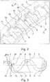
- FIG. 1 goes out for a Axialnadelellager suitable axial cage 1, which consists essentially of a thin-walled annular disc 2, which, as in particular FIG. 3 clearly shows, having a W-shaped profile cross-section.
- FIG. 1 in synopsis with FIG. 3 to see that the individual profile legs of the Axial hofigs 1 by an integrally formed on the inner edge of the annular disc 2 inner radial board 3, an integrally formed on the outer edge of the annular disc 2 outer radial board 4 and an inner and outer axial profile sections 5, 6 with the Borden 3, 4 connected U-shaped bead 7 are formed, which has the same radial extent as the shelves 3, 4. From the FIGS.
- FIGS. 2 and 3 show further that the outer radial board 4 according to the invention is formed with a direction away from the central U-shaped bead 7 slope ⁇ and the cage pockets 8 such a greater axial length than the smallest axial distance between the inner sides 11, 12 of the inner and outer radial Bordes 3, 4, that the cage pockets 8 extend into the outer radial rim 4 of the Axialklafigs 1 and by a spherical design of their outer end faces 13 to the pocket center on the outer radial rim 4 of the Axialklafigs 1 in the amount of unspecified Rolling axes of the rolling elements 10 form a rounded starting lug 14 for the outer end faces 15 of the rolling elements 10.
- the axial cage 1 is made of an endless sheet metal strip in a stepped punching tool and the rounded starting lugs 14 of the punched cage pockets 8 by designating the cutting gap with a smooth cutting surface 16 of about 10% a targeted punching rupture surface 17 of about 90% of Have material thickness of the axial cage 1.
- the smooth-cut surface 16 of the start-up lugs 14 is perpendicular to the inside 12 of the inclination ⁇ trained outer radial Bordes 4 of the Axialkafigs 1 incorporated and is in the amount of pocket longitudinal center with the end faces 15 of the rolling elements 10 in line contact, while the oblique from the smooth cutting surface 16 obliquely to the outside 18 of the board 4 punching rupture surface 17 of the start lugs 14 below the line contact between them and the end faces 15 of the rolling elements 10 is provided as a capillary for conveying lubricant to this contact.
- resulting from the rounded formation of the start-up lugs 14 free spaces 19, 20 provided on both sides of the line contact between them and the rolling elements 10 as discharge openings is discharged through the excess lubricant from the thrust bearing.
Landscapes
- Engineering & Computer Science (AREA)
- General Engineering & Computer Science (AREA)
- Mechanical Engineering (AREA)
- Rolling Contact Bearings (AREA)
Claims (7)
- Cage axiale (1) pour corps de roulement cylindriques, constituée essentiellement d'un disque annulaire à paroi mince (2) avec une section transversale de profilé en forme de W dont les branches de profilé individuelles sont formées par un bord radial interne (3) façonné au niveau du bord interne du disque annulaire (2), un bord radial externe (4) façonné au niveau du bord externe du disque annulaire (2) et une moulure en forme de U centrale (7) connectée par le biais de portions de profilé axiales interne et externe (5, 6) aux bords radiaux (3, 4) et présentant la même étendue radiale que les bords (3, 4), une pluralité de cavités de cage rectangulaires (8) espacées uniformément les unes des autres étant réalisées dans la moulure centrale (7) et dans les portions de profilé axiales adjacentes (5, 6), entre lesquelles est formé une pluralité identique de nervures de cavités (9) reliant les bords (3, 4) l'un à l'autre, par lesquelles nervures de cavités les corps de roulement cylindriques (10) sont retenus les uns par rapport aux autres à intervalles réguliers dans les cavités de cage (8) et sont guidés dans la direction périphérique, caractérisée en ce que le bord radial extérieur (4) est réalisé avec une inclinaison (α) orientée à l'écart de la moulure en forme de U centrale (7) et les cavités de cage (8) présentent une longueur axiale plus longue que la plus petite distance axiale entre les côtés internes (11, 12) des bords radiaux interne et externe (3, 4), de telle sorte que les cavités de cage (8) s'étendent au moins jusque dans le bord radial externe (4) de la cage axiale (1) et forment, par une réalisation bombée de leurs côtés frontaux externes (13) vers le centre de la cavité au niveau du bord radial externe (4) de la cage axiale (1) à la hauteur des axes de roulement des corps de roulement (10), un nez de butée arrondi (14) pour les côtés frontaux externes (15) des corps de roulement (10).
- Cage axiale selon la revendication 1, caractérisée en ce que l'inclinaison (α) du bord radial externe (4) est d'environ 15° par rapport à un axe médian vertical de la cage.
- Cage axiale selon la revendication 1, caractérisée en ce que la plus grande longueur axiale des cavités de cage (8) par rapport à la plus petite distance axiale entre les côtés internes (11, 12) des bords (3, 4) peut être produite par une réalisation raccourcie de la longueur de la section transversale de profilé axiale externe (6) par rapport à la longueur de la section transversale de profilé axiale interne (5).
- Cage axiale selon la revendication 1, caractérisée en ce que les cavités de cage (8) sont produites sans enlèvement de copeaux par estampage, leurs nez de butée arrondis (14) présentant une surface d'arrachement d'estampage (17) d'environ 90 % de l'épaisseur de matériau de la cage axiale (1) par conception de la fente de coupe avec une surface de coupe lisse (16) d'environ 10 %.
- Cage axiale selon la revendication 4, caractérisée en ce que la surface de coupe lisse (16) des nez de butée (14) est réalisée perpendiculairement dans le côté interne (11) du bord radial externe (4) de la cage axiale (1) réalisé avec l'inclinaison et se situe dans la hauteur du milieu longitudinal des cavités en contact linéaire avec les côtés frontaux (15) des corps de roulement (10).
- Cage axiale selon la revendication 5, caractérisée en ce que la surface d'arrachement d'estampage (17) des nez de butée (14) s'étendant obliquement par rapport au côté externe (18) du bord (4) depuis la surface de coupe lisse (16) est prévue sous le contact linéaire entre les nez de butée et les côtés frontaux (15) des corps de roulement (10) sous forme de capillaires pour transporter du lubrifiant vers ce contact.
- Cage axiale selon la revendication 5, caractérisée en ce que les espaces libres (19, 20) produits par la réalisation arrondie des nez de butée (14) des cavités de cage (8) sont prévus de chaque côté du contact linéaire entre ceux-ci et les côtés frontaux (15) des corps de roulement (10) sous forme d'ouvertures d'évacuation pour le lubrifiant en excès.
Applications Claiming Priority (2)
| Application Number | Priority Date | Filing Date | Title |
|---|---|---|---|
| DE102012215740.9A DE102012215740A1 (de) | 2012-09-05 | 2012-09-05 | Axialkäfig für zylindrische Wälzkörper |
| PCT/DE2013/200056 WO2014036997A1 (fr) | 2012-09-05 | 2013-07-17 | Cage axial pour corps de roulement cylindrique |
Publications (2)
| Publication Number | Publication Date |
|---|---|
| EP2893207A1 EP2893207A1 (fr) | 2015-07-15 |
| EP2893207B1 true EP2893207B1 (fr) | 2016-12-28 |
Family
ID=49080623
Family Applications (1)
| Application Number | Title | Priority Date | Filing Date |
|---|---|---|---|
| EP13753552.2A Active EP2893207B1 (fr) | 2012-09-05 | 2013-07-17 | Cage axiale pour corps de roulement cylindriques |
Country Status (7)
| Country | Link |
|---|---|
| US (1) | US9404537B2 (fr) |
| EP (1) | EP2893207B1 (fr) |
| JP (1) | JP2015528553A (fr) |
| KR (1) | KR20150046078A (fr) |
| CN (1) | CN104854357B (fr) |
| DE (1) | DE102012215740A1 (fr) |
| WO (1) | WO2014036997A1 (fr) |
Families Citing this family (7)
| Publication number | Priority date | Publication date | Assignee | Title |
|---|---|---|---|---|
| DE102014209236A1 (de) * | 2014-05-15 | 2015-11-19 | Schaeffler Technologies AG & Co. KG | Axialwälzlager und Axialwälzlagerkäfig |
| KR102508641B1 (ko) * | 2017-03-06 | 2023-03-10 | 엔티엔 가부시키가이샤 | 유지기가 부착된 바늘상 롤러 및 그것을 구비한 유성 기어 기구 지지 구조 |
| CN110382887B (zh) * | 2017-03-06 | 2021-05-25 | Ntn株式会社 | 带保持器的针状滚子和具有该带保持器的针状滚子的行星轮机构支承结构 |
| US10487877B2 (en) * | 2018-03-01 | 2019-11-26 | Schaeffler Technologies AG & Co. KG | Bearing cage including hydrodynamic feature |
| JP7356233B2 (ja) * | 2019-03-05 | 2023-10-04 | Ntn株式会社 | 保持器付きころおよびころ軸受 |
| WO2020191517A1 (fr) * | 2019-03-22 | 2020-10-01 | Schaeffler Technologies AG & Co. KG | Cage pour roulement, et roulement |
| US10941811B1 (en) * | 2020-01-14 | 2021-03-09 | Schaeffler Technologies AG & Co. KG | High-speed bearing |
Family Cites Families (25)
| Publication number | Priority date | Publication date | Assignee | Title |
|---|---|---|---|---|
| GB826173A (en) | 1956-02-10 | 1959-12-31 | Pitner Alfred | Improvements in or relating to needle bearings |
| DE1174113B (de) | 1962-02-20 | 1964-07-16 | Schaeffler Ohg Industriewerk | Axialkaefig fuer zylindrische Waelzkoerper |
| JPS58108622U (ja) * | 1982-01-20 | 1983-07-23 | 日本精工株式会社 | ころ軸受用保持器 |
| JPH0648182Y2 (ja) * | 1988-05-16 | 1994-12-12 | 光洋精工株式会社 | ころ軸受用保持器 |
| DE10143089B4 (de) | 2001-09-03 | 2010-07-29 | Schaeffler Technologies Gmbh & Co. Kg | Axialkäfig für zylindrische Wälzkörper und damit gebildete Axiallager |
| DE10326418A1 (de) * | 2002-07-02 | 2004-01-22 | Ina-Schaeffler Kg | Wälzlagerkäfig |
| JP2004144244A (ja) * | 2002-10-25 | 2004-05-20 | Koyo Seiko Co Ltd | ころ軸受用の保持器 |
| JP4165226B2 (ja) * | 2003-01-06 | 2008-10-15 | 株式会社ジェイテクト | スラストころ軸受用保持器 |
| JP4483365B2 (ja) * | 2004-03-24 | 2010-06-16 | 日本精工株式会社 | スラスト円筒ころ軸受用保持器とその製造方法 |
| JP4606128B2 (ja) * | 2004-11-11 | 2011-01-05 | 宇都宮機器株式会社 | ころ軸受用保持器の製造方法 |
| JP4432741B2 (ja) * | 2004-11-16 | 2010-03-17 | 株式会社ジェイテクト | スラストころ軸受用保持器 |
| JP4483803B2 (ja) * | 2005-03-03 | 2010-06-16 | 日本精工株式会社 | スラスト円筒ころ軸受 |
| JP2007224977A (ja) * | 2006-02-22 | 2007-09-06 | Jtekt Corp | スラストころ軸受 |
| US7896558B2 (en) * | 2006-06-06 | 2011-03-01 | Ntn Corporation | Thrust roller bearing |
| JP4817985B2 (ja) * | 2006-06-21 | 2011-11-16 | Ntn株式会社 | スラストころ軸受 |
| US20100008614A1 (en) * | 2006-07-17 | 2010-01-14 | Schaeffler Kg | Axial roller bearing |
| JP2008025611A (ja) * | 2006-07-18 | 2008-02-07 | Jtekt Corp | スラストころ軸受 |
| JP5186766B2 (ja) * | 2006-12-27 | 2013-04-24 | 株式会社ジェイテクト | スラストころ軸受 |
| JP2008175310A (ja) | 2007-01-19 | 2008-07-31 | Jtekt Corp | スラストころ軸受用保持器及びスラストころ軸受 |
| JP5104168B2 (ja) * | 2007-09-28 | 2012-12-19 | 株式会社ジェイテクト | 保持器およびその製造方法 |
| JP2010025250A (ja) * | 2008-07-22 | 2010-02-04 | Jtekt Corp | スラストころ軸受 |
| JP2010053888A (ja) * | 2008-08-26 | 2010-03-11 | Jtekt Corp | スラストころ軸受の保持器 |
| DE102008050232A1 (de) * | 2008-10-02 | 2010-04-08 | Schaeffler Kg | Wälzlager |
| JP2011144866A (ja) * | 2010-01-14 | 2011-07-28 | Jtekt Corp | スラストころ軸受 |
| DE102010019069A1 (de) | 2010-05-03 | 2011-11-03 | Schaeffler Technologies Gmbh & Co. Kg | Axialkäfig für zylindrische Wälzkörper |
-
2012
- 2012-09-05 DE DE102012215740.9A patent/DE102012215740A1/de not_active Withdrawn
-
2013
- 2013-07-17 KR KR1020157005469A patent/KR20150046078A/ko not_active Withdrawn
- 2013-07-17 WO PCT/DE2013/200056 patent/WO2014036997A1/fr not_active Ceased
- 2013-07-17 JP JP2015530296A patent/JP2015528553A/ja not_active Ceased
- 2013-07-17 EP EP13753552.2A patent/EP2893207B1/fr active Active
- 2013-07-17 US US14/424,641 patent/US9404537B2/en active Active
- 2013-07-17 CN CN201380046401.4A patent/CN104854357B/zh active Active
Non-Patent Citations (1)
| Title |
|---|
| None * |
Also Published As
| Publication number | Publication date |
|---|---|
| WO2014036997A1 (fr) | 2014-03-13 |
| US20150219158A1 (en) | 2015-08-06 |
| CN104854357A (zh) | 2015-08-19 |
| DE102012215740A1 (de) | 2014-03-06 |
| CN104854357B (zh) | 2017-04-12 |
| JP2015528553A (ja) | 2015-09-28 |
| US9404537B2 (en) | 2016-08-02 |
| EP2893207A1 (fr) | 2015-07-15 |
| KR20150046078A (ko) | 2015-04-29 |
Similar Documents
| Publication | Publication Date | Title |
|---|---|---|
| DE112011101552B4 (de) | Axialkäfig für zylindrische Wälzkörper | |
| EP2893207B1 (fr) | Cage axiale pour corps de roulement cylindriques | |
| EP2678576B1 (fr) | Cage de corps de roulement | |
| DE102010034254B4 (de) | Käfig für ein Rollenlager | |
| EP2691665B1 (fr) | Cage de palier à roulement et procédé de fabrication d'une cage de palier à roulement | |
| DE102008016977A1 (de) | Kugelrollenlager sowie Verfahren zur Montage eines solchen Kugelrollenlagers | |
| DE102011004374A1 (de) | Lagerkäfigsegment, Lagerkäfig und Verfahren zur Herstellung desselben | |
| EP2478235B1 (fr) | Roulement à rouleaux sphériques | |
| EP2213894A1 (fr) | Cage de palier de roulement | |
| DE112015005204T5 (de) | Halter für Druckrollenlager und Verfahren zur Herstellung des Halters | |
| DE102013203674A1 (de) | Käfigabschnitt und Verfahren zu seiner Herstellung | |
| EP2478236B1 (fr) | Roulement à rouleaux sphériques | |
| WO2008067792A2 (fr) | Cage de roulement | |
| EP2547925B1 (fr) | Coquille de coussinet lisse | |
| DE102013226132A1 (de) | Käfig für ein Wälzlager sowie Rollenlager mit einem Käfig | |
| EP2662581A2 (fr) | Cage pour un roulement | |
| EP3060821B1 (fr) | Cage axiale pour corps de roulement cylindriques | |
| DE102008037075A1 (de) | Kugelrollenlager, insbesondere zur Aufnahme einseitig höhere Axialkräfte, sowie Verfahren zur Montage eines solchen Kugelrollenlagers | |
| AT517814A2 (de) | Verfahren zur Herstellung einer Stahl- Reiblamelle für eine Reibungskupplung | |
| DE102008004046A1 (de) | Käfig für Wälzkörper | |
| DE965459C (de) | Nadelrollenkaefig | |
| EP3660344B1 (fr) | Procede de production d'une cage de roulement a rouleaux spheriques et cage de roulement produite selon ce procede | |
| DE102017221475A1 (de) | Lagerkäfig, Wälzlager und Verfahren | |
| DE112011104988T5 (de) | Wälzlager mit zumindest einem flexiblen Ring | |
| DE102018100392B3 (de) | Axialnadellager sowie Verfahren zur Herstellung einer Laufscheibe eines solchen Axialnadellagers |
Legal Events
| Date | Code | Title | Description |
|---|---|---|---|
| PUAI | Public reference made under article 153(3) epc to a published international application that has entered the european phase |
Free format text: ORIGINAL CODE: 0009012 |
|
| 17P | Request for examination filed |
Effective date: 20150407 |
|
| AK | Designated contracting states |
Kind code of ref document: A1 Designated state(s): AL AT BE BG CH CY CZ DE DK EE ES FI FR GB GR HR HU IE IS IT LI LT LU LV MC MK MT NL NO PL PT RO RS SE SI SK SM TR |
|
| AX | Request for extension of the european patent |
Extension state: BA ME |
|
| DAX | Request for extension of the european patent (deleted) | ||
| RIC1 | Information provided on ipc code assigned before grant |
Ipc: F16C 19/30 20060101ALN20160721BHEP Ipc: F16C 33/54 20060101AFI20160721BHEP |
|
| GRAP | Despatch of communication of intention to grant a patent |
Free format text: ORIGINAL CODE: EPIDOSNIGR1 |
|
| INTG | Intention to grant announced |
Effective date: 20161010 |
|
| GRAS | Grant fee paid |
Free format text: ORIGINAL CODE: EPIDOSNIGR3 |
|
| GRAA | (expected) grant |
Free format text: ORIGINAL CODE: 0009210 |
|
| AK | Designated contracting states |
Kind code of ref document: B1 Designated state(s): AL AT BE BG CH CY CZ DE DK EE ES FI FR GB GR HR HU IE IS IT LI LT LU LV MC MK MT NL NO PL PT RO RS SE SI SK SM TR |
|
| REG | Reference to a national code |
Ref country code: GB Ref legal event code: FG4D Free format text: NOT ENGLISH |
|
| REG | Reference to a national code |
Ref country code: CH Ref legal event code: EP |
|
| REG | Reference to a national code |
Ref country code: AT Ref legal event code: REF Ref document number: 857576 Country of ref document: AT Kind code of ref document: T Effective date: 20170115 |
|
| REG | Reference to a national code |
Ref country code: IE Ref legal event code: FG4D Free format text: LANGUAGE OF EP DOCUMENT: GERMAN |
|
| REG | Reference to a national code |
Ref country code: DE Ref legal event code: R096 Ref document number: 502013005922 Country of ref document: DE |
|
| PG25 | Lapsed in a contracting state [announced via postgrant information from national office to epo] |
Ref country code: LV Free format text: LAPSE BECAUSE OF FAILURE TO SUBMIT A TRANSLATION OF THE DESCRIPTION OR TO PAY THE FEE WITHIN THE PRESCRIBED TIME-LIMIT Effective date: 20161228 |
|
| REG | Reference to a national code |
Ref country code: LT Ref legal event code: MG4D |
|
| PG25 | Lapsed in a contracting state [announced via postgrant information from national office to epo] |
Ref country code: LT Free format text: LAPSE BECAUSE OF FAILURE TO SUBMIT A TRANSLATION OF THE DESCRIPTION OR TO PAY THE FEE WITHIN THE PRESCRIBED TIME-LIMIT Effective date: 20161228 Ref country code: GR Free format text: LAPSE BECAUSE OF FAILURE TO SUBMIT A TRANSLATION OF THE DESCRIPTION OR TO PAY THE FEE WITHIN THE PRESCRIBED TIME-LIMIT Effective date: 20170329 Ref country code: NO Free format text: LAPSE BECAUSE OF FAILURE TO SUBMIT A TRANSLATION OF THE DESCRIPTION OR TO PAY THE FEE WITHIN THE PRESCRIBED TIME-LIMIT Effective date: 20170328 Ref country code: SE Free format text: LAPSE BECAUSE OF FAILURE TO SUBMIT A TRANSLATION OF THE DESCRIPTION OR TO PAY THE FEE WITHIN THE PRESCRIBED TIME-LIMIT Effective date: 20161228 |
|
| REG | Reference to a national code |
Ref country code: NL Ref legal event code: MP Effective date: 20161228 |
|
| PG25 | Lapsed in a contracting state [announced via postgrant information from national office to epo] |
Ref country code: RS Free format text: LAPSE BECAUSE OF FAILURE TO SUBMIT A TRANSLATION OF THE DESCRIPTION OR TO PAY THE FEE WITHIN THE PRESCRIBED TIME-LIMIT Effective date: 20161228 Ref country code: FI Free format text: LAPSE BECAUSE OF FAILURE TO SUBMIT A TRANSLATION OF THE DESCRIPTION OR TO PAY THE FEE WITHIN THE PRESCRIBED TIME-LIMIT Effective date: 20161228 Ref country code: HR Free format text: LAPSE BECAUSE OF FAILURE TO SUBMIT A TRANSLATION OF THE DESCRIPTION OR TO PAY THE FEE WITHIN THE PRESCRIBED TIME-LIMIT Effective date: 20161228 |
|
| PG25 | Lapsed in a contracting state [announced via postgrant information from national office to epo] |
Ref country code: NL Free format text: LAPSE BECAUSE OF FAILURE TO SUBMIT A TRANSLATION OF THE DESCRIPTION OR TO PAY THE FEE WITHIN THE PRESCRIBED TIME-LIMIT Effective date: 20161228 |
|
| REG | Reference to a national code |
Ref country code: FR Ref legal event code: PLFP Year of fee payment: 5 |
|
| PG25 | Lapsed in a contracting state [announced via postgrant information from national office to epo] |
Ref country code: CZ Free format text: LAPSE BECAUSE OF FAILURE TO SUBMIT A TRANSLATION OF THE DESCRIPTION OR TO PAY THE FEE WITHIN THE PRESCRIBED TIME-LIMIT Effective date: 20161228 Ref country code: IS Free format text: LAPSE BECAUSE OF FAILURE TO SUBMIT A TRANSLATION OF THE DESCRIPTION OR TO PAY THE FEE WITHIN THE PRESCRIBED TIME-LIMIT Effective date: 20170428 Ref country code: SK Free format text: LAPSE BECAUSE OF FAILURE TO SUBMIT A TRANSLATION OF THE DESCRIPTION OR TO PAY THE FEE WITHIN THE PRESCRIBED TIME-LIMIT Effective date: 20161228 Ref country code: EE Free format text: LAPSE BECAUSE OF FAILURE TO SUBMIT A TRANSLATION OF THE DESCRIPTION OR TO PAY THE FEE WITHIN THE PRESCRIBED TIME-LIMIT Effective date: 20161228 Ref country code: RO Free format text: LAPSE BECAUSE OF FAILURE TO SUBMIT A TRANSLATION OF THE DESCRIPTION OR TO PAY THE FEE WITHIN THE PRESCRIBED TIME-LIMIT Effective date: 20161228 |
|
| PG25 | Lapsed in a contracting state [announced via postgrant information from national office to epo] |
Ref country code: BG Free format text: LAPSE BECAUSE OF FAILURE TO SUBMIT A TRANSLATION OF THE DESCRIPTION OR TO PAY THE FEE WITHIN THE PRESCRIBED TIME-LIMIT Effective date: 20170328 Ref country code: SM Free format text: LAPSE BECAUSE OF FAILURE TO SUBMIT A TRANSLATION OF THE DESCRIPTION OR TO PAY THE FEE WITHIN THE PRESCRIBED TIME-LIMIT Effective date: 20161228 Ref country code: ES Free format text: LAPSE BECAUSE OF FAILURE TO SUBMIT A TRANSLATION OF THE DESCRIPTION OR TO PAY THE FEE WITHIN THE PRESCRIBED TIME-LIMIT Effective date: 20161228 Ref country code: PT Free format text: LAPSE BECAUSE OF FAILURE TO SUBMIT A TRANSLATION OF THE DESCRIPTION OR TO PAY THE FEE WITHIN THE PRESCRIBED TIME-LIMIT Effective date: 20170428 Ref country code: PL Free format text: LAPSE BECAUSE OF FAILURE TO SUBMIT A TRANSLATION OF THE DESCRIPTION OR TO PAY THE FEE WITHIN THE PRESCRIBED TIME-LIMIT Effective date: 20161228 |
|
| REG | Reference to a national code |
Ref country code: DE Ref legal event code: R097 Ref document number: 502013005922 Country of ref document: DE |
|
| PGFP | Annual fee paid to national office [announced via postgrant information from national office to epo] |
Ref country code: FR Payment date: 20170727 Year of fee payment: 5 Ref country code: IT Payment date: 20170720 Year of fee payment: 5 |
|
| PLBE | No opposition filed within time limit |
Free format text: ORIGINAL CODE: 0009261 |
|
| STAA | Information on the status of an ep patent application or granted ep patent |
Free format text: STATUS: NO OPPOSITION FILED WITHIN TIME LIMIT |
|
| PG25 | Lapsed in a contracting state [announced via postgrant information from national office to epo] |
Ref country code: DK Free format text: LAPSE BECAUSE OF FAILURE TO SUBMIT A TRANSLATION OF THE DESCRIPTION OR TO PAY THE FEE WITHIN THE PRESCRIBED TIME-LIMIT Effective date: 20161228 |
|
| 26N | No opposition filed |
Effective date: 20170929 |
|
| PG25 | Lapsed in a contracting state [announced via postgrant information from national office to epo] |
Ref country code: SI Free format text: LAPSE BECAUSE OF FAILURE TO SUBMIT A TRANSLATION OF THE DESCRIPTION OR TO PAY THE FEE WITHIN THE PRESCRIBED TIME-LIMIT Effective date: 20161228 |
|
| REG | Reference to a national code |
Ref country code: CH Ref legal event code: PL |
|
| GBPC | Gb: european patent ceased through non-payment of renewal fee |
Effective date: 20170717 |
|
| REG | Reference to a national code |
Ref country code: IE Ref legal event code: MM4A |
|
| PG25 | Lapsed in a contracting state [announced via postgrant information from national office to epo] |
Ref country code: CH Free format text: LAPSE BECAUSE OF NON-PAYMENT OF DUE FEES Effective date: 20170731 Ref country code: GB Free format text: LAPSE BECAUSE OF NON-PAYMENT OF DUE FEES Effective date: 20170717 Ref country code: LI Free format text: LAPSE BECAUSE OF NON-PAYMENT OF DUE FEES Effective date: 20170731 Ref country code: IE Free format text: LAPSE BECAUSE OF NON-PAYMENT OF DUE FEES Effective date: 20170717 |
|
| REG | Reference to a national code |
Ref country code: BE Ref legal event code: MM Effective date: 20170731 |
|
| PG25 | Lapsed in a contracting state [announced via postgrant information from national office to epo] |
Ref country code: LU Free format text: LAPSE BECAUSE OF NON-PAYMENT OF DUE FEES Effective date: 20170717 |
|
| PG25 | Lapsed in a contracting state [announced via postgrant information from national office to epo] |
Ref country code: BE Free format text: LAPSE BECAUSE OF NON-PAYMENT OF DUE FEES Effective date: 20170731 |
|
| PG25 | Lapsed in a contracting state [announced via postgrant information from national office to epo] |
Ref country code: MT Free format text: LAPSE BECAUSE OF FAILURE TO SUBMIT A TRANSLATION OF THE DESCRIPTION OR TO PAY THE FEE WITHIN THE PRESCRIBED TIME-LIMIT Effective date: 20161228 |
|
| PG25 | Lapsed in a contracting state [announced via postgrant information from national office to epo] |
Ref country code: FR Free format text: LAPSE BECAUSE OF NON-PAYMENT OF DUE FEES Effective date: 20180731 |
|
| PG25 | Lapsed in a contracting state [announced via postgrant information from national office to epo] |
Ref country code: MC Free format text: LAPSE BECAUSE OF FAILURE TO SUBMIT A TRANSLATION OF THE DESCRIPTION OR TO PAY THE FEE WITHIN THE PRESCRIBED TIME-LIMIT Effective date: 20161228 Ref country code: HU Free format text: LAPSE BECAUSE OF FAILURE TO SUBMIT A TRANSLATION OF THE DESCRIPTION OR TO PAY THE FEE WITHIN THE PRESCRIBED TIME-LIMIT; INVALID AB INITIO Effective date: 20130717 |
|
| PG25 | Lapsed in a contracting state [announced via postgrant information from national office to epo] |
Ref country code: IT Free format text: LAPSE BECAUSE OF NON-PAYMENT OF DUE FEES Effective date: 20180717 |
|
| REG | Reference to a national code |
Ref country code: AT Ref legal event code: MM01 Ref document number: 857576 Country of ref document: AT Kind code of ref document: T Effective date: 20180717 |
|
| PG25 | Lapsed in a contracting state [announced via postgrant information from national office to epo] |
Ref country code: CY Free format text: LAPSE BECAUSE OF FAILURE TO SUBMIT A TRANSLATION OF THE DESCRIPTION OR TO PAY THE FEE WITHIN THE PRESCRIBED TIME-LIMIT Effective date: 20161228 |
|
| PG25 | Lapsed in a contracting state [announced via postgrant information from national office to epo] |
Ref country code: MK Free format text: LAPSE BECAUSE OF FAILURE TO SUBMIT A TRANSLATION OF THE DESCRIPTION OR TO PAY THE FEE WITHIN THE PRESCRIBED TIME-LIMIT Effective date: 20161228 |
|
| PG25 | Lapsed in a contracting state [announced via postgrant information from national office to epo] |
Ref country code: AT Free format text: LAPSE BECAUSE OF NON-PAYMENT OF DUE FEES Effective date: 20180717 |
|
| PG25 | Lapsed in a contracting state [announced via postgrant information from national office to epo] |
Ref country code: TR Free format text: LAPSE BECAUSE OF FAILURE TO SUBMIT A TRANSLATION OF THE DESCRIPTION OR TO PAY THE FEE WITHIN THE PRESCRIBED TIME-LIMIT Effective date: 20161228 |
|
| PG25 | Lapsed in a contracting state [announced via postgrant information from national office to epo] |
Ref country code: AL Free format text: LAPSE BECAUSE OF FAILURE TO SUBMIT A TRANSLATION OF THE DESCRIPTION OR TO PAY THE FEE WITHIN THE PRESCRIBED TIME-LIMIT Effective date: 20161228 |
|
| P01 | Opt-out of the competence of the unified patent court (upc) registered |
Effective date: 20230523 |
|
| PGFP | Annual fee paid to national office [announced via postgrant information from national office to epo] |
Ref country code: DE Payment date: 20250919 Year of fee payment: 13 |